Important: Delayed Conduction in Bucking Coils

  • Topic Is Sticky
  • Topic Is Locked
  • 16K Views
  • Last Post 24 February 2024
Chris posted this 11 March 2019

My Friends,

The Effects of Delayed Conduction in Bucking Coils is important. What is Delayed Conduction? What is the point of this?

Delayed Conduction is specifically to get the Voltage on the Terminals of your Partnered Output Coils as high as possible in reason! Its the change in Magnetic Field that Creates Voltage, its the Opposition of Magnetic Fields that Pumps Current! 

Circuitry can also be employed to delay Conduction on the second Partnered Output Coil.

Ref: How to build your own Above Unity Machine


I gave an example of Delayed Conduction here.

As you can see, the Mosfets will only conduct when the Zener Diodes Conduct, this is rated to 18 Volts.

This means, the ends of the Partnered Output Coils must be at least 18 Volts, before the Coils can power any load!

We have seen this before! This is not new to those that have done the Study!


The MEG Demo Circuit

Where D2 represents a Bi-Directional TVS.


Ref: JLN MEG Replication


Ref: The MEG Team Data.

Where the Top Trace represents the Input Channels, and the bottom Trace Magnetic Resonance in the Output Coils, seen as Asymmetrical Regauging.


NOTE: JLN used a MOV in his MEG Replication. A MOV has similar Voltage to Current Characteristics! 


Ref: JonRB


Ref: Renesas Datasheet


Ref: The MOV or Varistor V I Characteristics


I want to stress the point of getting the Voltage on the Terminals of your Partnered Output Coils to a maximum without being disturbed. Input Creates a Voltage on your Terminals, then the Input is switched off. Then your Partnered Output Coils Conduct and we Pump Current.

Remember: Some of these Circuits may require an Earth Ground.

   Chris

Order By: Standard | Newest | Votes
Forelle posted this 26 April 2019

Hi Chris 

No problem ,i have asked so complicated that you have to answer like you did.

I asked this question because i have made the 180° phaseshift with air core coils and Ac( signal not power,for this coils it was at about 3.5Mhz) and there it is no problem,you dial the frequencygenerator until you have it,but with my flyback core i have tried many different configurations and had only slightly phaseshift of max.2 degrees,and the core does not go more than 200khz and the wave gets so small you cant see it anymore.Maybe i should change to an other core.I have tried the Mr.Preva experiment but ther it was the same,i take staff that i have at home,the biggest problem i have is that i fall 100% under Murphys law.laughingBut i think i have understood most of what you showed us.

Good day

  • Liked by
  • Chris
  • Vidura
Vidura posted this 26 April 2019

Hi Forelle You could try at much lower frequency, it is normal for most cores that the losses become too large at high frequencies, and the signal vanished. You can find here some information about second order magnetic fields: http://gorchilin.com/articles/coil/magneticwaveresonance?lang=en I hope this helps, Vidura.

  • Liked by
  • Chris
Chris posted this 26 April 2019

Hey Forelle,

Vidura is right, much lower Frequencies.

Also, Current ( I ) through Turns ( N ) is Magnetomotive Force. Increase your Turns to see Forces at work wink

Getting a feeling for The Mr Preva Experiment is, in my humble opinion, very beneficial! I would recommend becoming acquainted.

   Chris

  • Liked by
  • Vidura
  • Aetherholic
Forelle posted this 26 April 2019

Hi

I start at 30 hz and go up so far until the core can't handle it anymore because i am at the beginning and dont know the device and do not know  when the phaserelation starts to change.I have L1 12 and and L2L3 36 windings with a flyback core with 7x4 cm..Yesterday i startet to build a other one with a 3C90 core 100/57/25 ,i thought i start with L1 20 and L2 L3 80 windings of 1,3mm wire.Since i know what i have to do it is not realy frustrating if it doesnt work from the beginning.

Vidura thanks for the link.

https://www.tme.eu/at/details/u100_57_25-3c90/ferritkerne/ferroxcube/u100-57-25-3c90/

Oliver


  • Liked by
  • Vidura
  • Chris
patrick1 posted this 28 April 2019

Hi,  I just finished my new circuit too test. - , it can;

1.detect a positive voltage and start a timer too determine the delay before conduction,

2.create the conduction pulse, with another timer,   ,    simple right ?...  using 2 breadboards and 6 ics.   lol..!!

does anyone have any tips, assuming a square wave positive offset input. ...   i am more likley too find a sweet spot, by rebounding 90% of the input pulse, or just the last 10% ;-D.....

one other concern i have is that it wont work at all with a positive only offset square wave input. -   perhaps i will need a h bridge.


Jagau posted this 28 April 2019

Sorry patrick but I can not see which circuit you're talking about,

could that help me give you an opinion?


Jagau

  • Liked by
  • Chris
Chris posted this 29 April 2019

Hi Patrick,

Sounds very ingenius!

Please post a image of the circuit so we can comment on it, that is, if that's want you want?

I have found, sometimes, the simpler the better. With Spikes, I have blown quite a bit of equipment, so please be careful.

   Chris

  • Liked by
  • Jagau
Chris posted this 30 April 2019

Hi my Friends,

Well, a distraction, goal achieved, one down on me.

The following, simple, cheap, circuit, controls the speed of a 2000 Watt Vacuum Cleaner:


From Full Speed, to less than half speed approximately. The simple Circuit:


There is beauty in Simplicity. Blue is Mains Neutral, Brown is Mains Hot, or Active Line. Red is Motor in and Motor Out. The waveform:


The same ideas apply, the same triggering applies, Delayed Conduction, this is one mechanism. And, its important!

   Chris

Chris posted this 01 May 2019

My Friends,

I have said before, I do not like the term Ferroresonance. Magnetic Resonance is a much better term, I am going to say, they are the same thing. Personally, in all the vagueness of both phenomena, I cannot find a difference.

It is well researched, Transformer Over Voltages, but it is not well documented that Switching, or lack of switching can induce Magnetic Resonance.


There is no difference between Delayed Conduction:


Now and again one may pick up a nugget or two! I have attached some pdf documents below.

If you have a minute, I would recommend a read here:

Ferro-resonance due to interruption of magnetizing currents of a cable fed transformer


   Chris

Attached Files

Chris posted this 01 May 2019

My Friends,

As we know, have covered in many places for a long time now, we have an Input Coil that is switched on, as the Current Ramps up / Changes in Time, our Output Coils have an Induced Voltage on then according to Faradays Law of Electromagnetic Induction.


A Voltage is Induced, and because we have a Load on one Coil, a Current is drawn. Very simple Science. Exactly the same process occurs on the Third, or Second Partnered Output Coil, except this Coil has no Load, no Current is flowing in this Coil, it is Open Circuit.

But, not for long!

The Input Coil's Current Ramps Up like so:


This indicated, and should be clear now, that we have a Time relationship, the On Time vs the Delayed Conduction Time, we need to find that happy medium, or the sweet spot, were the Input is only on long enough to trigger the process and the Trigger process is fast enough to induce enough Output Voltage, E.M.F = -Ndφ/dt, yes a Transient, time rate of change, to get the Partnered Output Coils working.

In the below Image, the Top Trace, the Input, its short timed, just enough to get the Coils to do their thing!


We switch in the Second Partnered Output Coil, in the form of Delayed Conduction technique, and this is what happens:


Partnered Output Coils Pump Current, as long as the Potential is high enough:


Ask any scientist, any Physicist: "Does it cost us anything for Voltage" then ask: "Does it cost anything for Current" - Then ask WHY!!! You will not get an answer forth coming!

We have already covered, Current is MMF, Magnetomotive Force, it must be supported and an Equal and Opposite Current MUST Support it.

All you have to do is start the Pump!

   Chris


P.S: Thank You! You are all Awesome!

Atti posted this 01 May 2019

Hi everyone.
I was curious about how a phenomenon develops.
How the power of the recorded current may decrease as the same secondary voltage. Or more.
It is related to my own thoughts and my own experiment.

But I mix another topic now. You must have remembered Tinman's rotating transformer. I know Chris did the experiment. You say what you think.

A similar theory is not a motor but a transformer. Therefore:
-Only with a self-closing oscillator, the demonstration works!
If you observe Tinman's rotating transformer, its speed (frequency) will also change.
-The load also affects.
-Reduced Frequency (TL494, SG..555) does not have a decrease in current strength. I tried it almost everywhere.
-No, it's not due to demagnetization.
- Even if the secondary side load is a half-wave diode or graetz bridge.
- Even if the secondary roll consists of a row.
- Only if we use the Chris layout.
-The load must be pulse-like in the Chris coil arrangement. Think of Mr Preva's experiment.
-Maximum 20% may be the fill factor.

I must have been wrong in many places!
I did this experiment quickly with the existing materials. It was not necessary to prepare for this purpose. Once again, it's just a demo to examine the effect. I think there is no special magic or the like.

I trust that the translation is understandable.
I will continue.

Chris posted this 02 May 2019

My Friends,


A terrible attempt at a Timing Chart! However, the Indicator ( I ) is the Input to the Mosfet ( Q1 ). The Indicator ( O ) is the Input to ( Q2 ). Now Frequency and Duty Cycle will vary, but you get the idea.

Q2 is on for a lot longer than Q1, Q1 is only a Trigger, to get the Potentials up.


Each and every Coil has one of these, and when timed right, the Magnetic Resonance creates some amazing effects!.

   Chris

Chris posted this 02 May 2019

Hi Patrick,

I have recommended the use of a Microcontroller to people. See: Reliable and Flexible Switching System 

CD_Sharp is now using a microcontroller, a Netduino and it appears it has become a main part of his tool kit.

Easy and flexible, easy to program, easy to get an output pulse train of your design. The complexity's of building small PWM circuits mostly dissaprars.

If we can all agree on a single model, and if the model does not come to EOL too soon then I can share some very fancy software to drive these machines.

Pushing a button, if the frequency is at 50Khz is going to be tricky, thus the reason I an suggesting a Micro:


Thanks for sharing, its always good to see progress!

   Chris


  • Liked by
  • Vidura
  • Aetherholic
Chris posted this 03 May 2019

My Friends,

Time is a critical factor in these configurations! Timing is made easy when we have simple Hardware to make changes in Time easier! Using a Microcontroller, or a simple Circuit, designed to make these changes with the adjustment of a Potentiometer.

REMEMBER: We have proof of the delayed switching of Graham Gunderson's MIT:


For new comers, and there appears to be a huge amount from all over the world! Please take the time to read the entire thread and all supporting threads. Its worth your time to make sure you know what the material I am sharing is about!

Don't forget, the Timing of the Conduction of the Output Coils is very important!

Getting this right will give you a machine that "Generates" much more energy Out than you put in!

   Chris

Chris posted this 04 May 2019

My Friends,

This is another video for those interested in looking at Microcontrollers:


How cool is that? I learnt a few new things in there also!

   Chris


P.S: I have moved Patricks posts out to his own thread so we can see his progress more accurately. Thanks Patrick!

  • Liked by
  • mrblobby
  • cd_sharp
Chris posted this 04 May 2019

My Friends,

I think its important to note, in Electronics Engineering, what I am showing you, is considered a big no no!

But WHY and HOW is this painted as a Big No No? Lets have a look at how they drum this into you:


Switching Harmonics, but why are Harmonics dangerous? Especially the third?


Now, truly this explanation is completely useless and explains nothing!

When it is said: "Dangerous", what is really meant, is the fact that Energy is "Generated" is excessive amounts and can blow your circuitry to smithereens. Honest to God truth! But they cant tell you that, because its one of those closely held secrets!

If you remember what Tom Bearden said about Non-Linear Loads?


So, we are looking for Harmonics, this is what we are aiming for, Big Harmonics, because we know how to Pump Current!


We want, which is exactly the situation in the above Video, a pretty reasonable Harmonic for this reason!

   Chris


P.S: Brad aka Tinman is still visiting our pages, looking for information! So be careful, do not post to much, or it will be stolen, and then claimed as his, this is the case with his latest Carbon Battery @www.youtube.com ( sKEMw3ZpTUM, gsTdr2eFRpE ), an invention of Carl Gassner in 1881. A whole bunch of people going crazy over a 100 year old invention, repainted, today as a new and amazing super capacitor. People so need to do their homework! tongue-out

Chris posted this 05 May 2019

My Friends,

I would like to introduce a way of thinking, that may advance your thinking tremendously, if you have not already begun to adopt this idea.

A Potential, or a Voltage is a difference from one point to another.

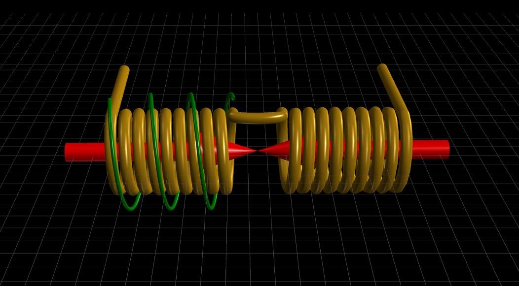
When dealing with a Wire, we have an Insulated Conductor that has one Terminal at one Potential and another Terminal at a different Potential.

We measure these differences in Potentials on our Oscilloscopes:


All pretty simple so far!


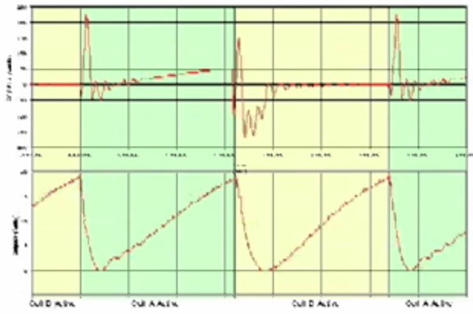
Now, If we look at Harmonics, what do we see? We see what is termed Distortion. A very important word Distortion, because this is not actually a correct term for what is occurring!

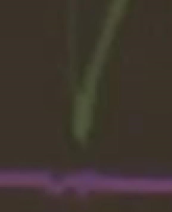
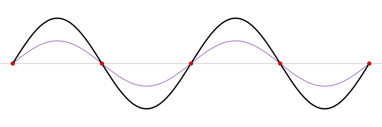
Lets look at this waveform:


A rough analogy of occurrences and Interactions between waveforms. The Green waveform is showing what is termed as Distortion. Normally Distortion is something that is recommended to avoid. It is drummed into engineers minds all through their training, textbooks and lecturers repeat this continually, its almost like a type of brain washing. Repetitive Suggestion.

We must stop and ask ourselves what's really occurring? What is truly occurring?

What is occurring is Superposition of Potentials in Time.


We have covered Superposition many times, so at this stage the penny will drop!

How?

We have a Voltage that is "Generated" that is in the reverse direction, so on the Green line, we have a Dip, at the peak, this is directly related to the Purple trace, which has a phase that is approximately 180 Degrees out of phase to the Green line. So if we were to take a simple 1 + -1 equation then we loose amplitude at this particular point in time.

We have Harmonics, ONLY because we have "Generated" Potentials, and thus Currents must flow, in a direction that can be subtractive to our Source! This is critical to see.

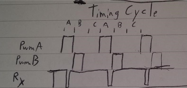
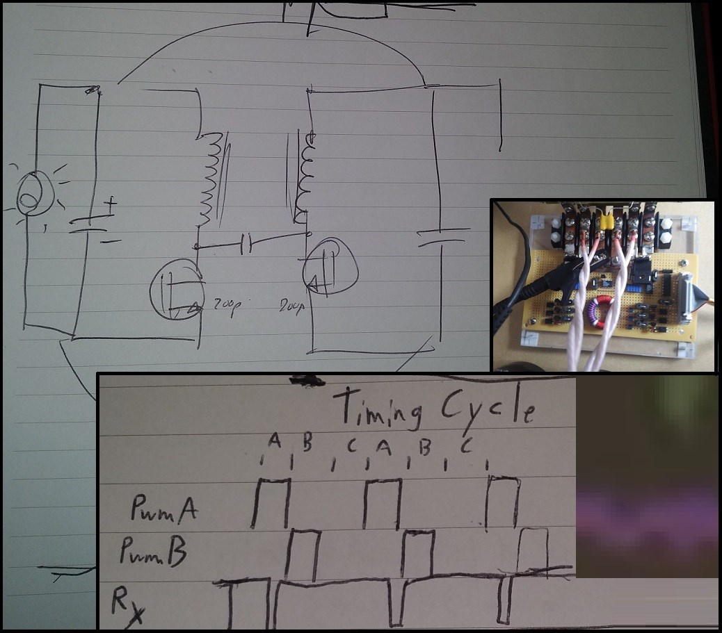
"Generated" Potentials, which can be additive or subtractive depending on the Harmonic we are looking at:


An example of harmonics, were we can see relationships. For example, 1/2 is directly in the middle of the first waveform, called the Fundamental normally.

Why does the Wave on the beach Slap so hard into the Incoming wave? Because there is a relationship to the Fundamental that "Creates" a larger Fundamental, remember Tom Bearden's video?


What did he say: "A larger Fundamental" so how does our wave Relationship work?

Two wave forms in, to make a larger Fundamental, well, again, we have seen this, on the beach:


The Timing is the Relationship, the Wave are the Actions, together, they can create a larger Fundamental!

So, by using Delayed Conduction, we introduce our Second Wave Form, this is the Timing part, where the Delay in Conduction creates a Second, not normally present, which is considered to be a Harmonic, and engineers are told to avoid, Waveform that does the very same Slapping together with the First Waveform, creating the larger Fundamental.

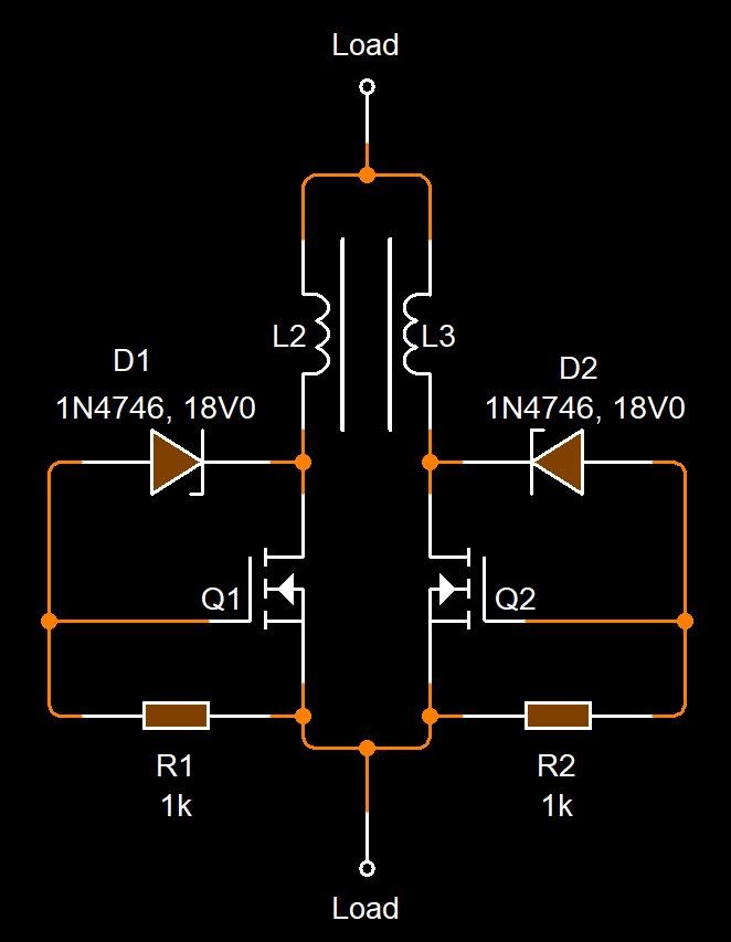
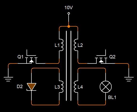
The entire Machine is Non-Linear!

The Coils and the Timing of them are Non-Linear!

The Switch to create the Delayed Conduction is Non-Linear.

The Load is Linear, as a load can be.

So, I ask you to think on this! Its important! Its the Actions in the Machine, we are creating a Non-Linear operating Machine. There is no Magic, its simple, its just a case of following the very simple rules I have laid out, I have taken a long time to learn this and to lay it out in a way I hope others can understand.

   Chris

Vidura posted this 05 May 2019

To think about the harmonics is really important, in the chart here you can easily see why the third harmonic is specially "dangerous". As all odd numbers of harmonics the middle peak adds to the fundamental frequency, and in the third the amplitude is the greatest. I remember some transformer testing when due to overload of the audio amplifier a harmonic was produced, and I measured values very close to unity while the amplifier was dissipating considerable heat. Vidura.

  • Liked by
  • Chris
  • Aetherholic
Chris posted this 06 May 2019

My Friends,

Yes exactly.


Voltage has a Polarity and the Superposition of Potential can reduce or reinforce the fundamental. Constructive or destructive reinforcement. An example of this is the Tesla Switch:


Current has a Polarity and the Superposition of Current can reduce or reinforce the fundamental. Constructive or destructive reinforcement. An Example of this is The Mr Preva Experiment:


Superposition of Voltage and Current are different! These two work in opposite ways, only under certain conditions!

   Chris

  • Liked by
  • Vidura
  • Aetherholic
patrick1 posted this 06 May 2019

I really think i am see'ing the effects today Chris !! 

my revelation of the day , for today is ;      ( these usually become redundant almost every single day )

That, - the circuitry is not very important, - i FEEL great, about my circuit, - but i think too make a successful transformer, - its most important too build the transformer too suit the job....     i feel there is infinite recipes for a suitable circuit, - but only one for the suitable transformer build.

and of course the lessons and experience is invaluable, because its all pointless if you dont understand it....   unlike conventional electronics.


Chris posted this 07 May 2019

Hey Patrick,

Yes, the recipe is simple, Three Coils, One Input, Two Output Coils, Drive as this thread explains very well. Look for the effects and improve the effects to the best of your ability.

   Chris

Chris posted this 08 May 2019

My Friends,

I hope, soon, people will understand the significance of my showing this image:


In combination with my very familiar image:


These images give you Voltage and Current Polarity, some polarity's that Science may not agree with. Giving you Energy that is in reverse to Current Conventional Energy.

I want to make a special note to all readers, this is more important than anyone can currently realise! Use this in combination with the information recently shown in my videos and in my posts and its very easy, with the right equipment to make a machine that "Generates" a lot more Energy than is input!

   Chris

Chris posted this 08 May 2019

Hey Vasile,

Member L0stf0x has done a lot of excellent work here, very successful results! Split the Positive

Hope this helps some!

   Chris

  • Liked by
  • Vasile
Dadrev posted this 08 May 2019

@chris

Entiendo que rectificamos la corriente AC y hacemos correr positiva de un lado y negativa, retrasada de otro. Es el camino?

Saludos...

Saludos...

  • Liked by
  • Chris
Chris posted this 08 May 2019

Hola Dadrev, No, es todo de salida DC. El voltaje es solo el potencial, se mantiene lo más alto posible debido a nuestra geometría de circuito. Tenemos dos caminos actuales iguales y opuestos, uno positivo, uno negativo. ¡La Corriente Negativa como se describe en otras publicaciones tiene algunas características inusuales!

Sin embargo, no creo en toda esta basura de energía radiante! Creo en intentar explicar lo que tenemos en términos científicos adecuados que todos con sus cabezas atornilladas pueden comprender.

Su energía negativa, su opuesto a la energía positiva, tiene un flujo de corriente que es inverso. Entonces, la polaridad del voltaje es de una manera, la corriente es lo opuesto.


Hi Dadrev, No it's all DC Output. The Voltage is Just the Potential, it is held as High as possible because of our Circuit Geometry. We have two equal and opposite Current paths, one Positive, one Negative. Negative Current as described in other posts has some unusual characteristics to it!

However, I do not believe in all this Radiant Energy Garbage! I believe in attempting to explain what we have in proper scientific terms that all with their heads screwed on can grasp.

Its Negative Energy, its opposite to Positive Energy, it has a Current flow that's in reverse. So Voltage Polarity is one way, Current is the opposite.


Apologies, I hope Google Translate has done a good job!

I hope this helps some!

   Chris

  • Liked by
  • Vidura
Chris posted this 08 May 2019

My Friends,

I need to clarify!

No it's all DC Output.


What I mean by this, is, You push up, it must come Down, you push Down, it must come back Up, the polarity is depends entirely on which Direction you are pocking the stick at. 

Again, AC is just DC Half Cycles of differing Polarity compared to a Specific Reference Point. Normally this Reference Point is the Earth.

I hope this helps!

   Chris

  • Liked by
  • Aetherholic
  • Vidura
patrick1 posted this 09 May 2019

I dont mean too poke a sleeping dragon, - im having difficulty making this work at all even in easy mode,-   but  what if its actaully easier too have dual input coils, aswell as dual output coils....     the question is, - can you setup a transformer geometry too be both efficient, and accept counter emf's on the input at the same time... by being far enough apart ,     and yet the bucking coils are close enough together too interact...   

Chris one of your transformers had 4 coils, and magnets, - is that your pies-ta reluctance ?

  • Liked by
  • Chris
Chris posted this 09 May 2019

Hey Patrick,

You're not poking a sleeping dragon.

There is a little fiddling to this, I have said this before. Do not fear, because a clear focused mind can easily work out what's going wrong. 

  1. Your Input is a Frequency around 200Hz with a 10% Duty Cycle?
  2. Your Input Voltage is around 2 - 10 Volts?
  3. Your Input to Output Ratio is around 1 to 3?


What Circuit are you using on the Output for Delayed Conduction? Do you know for sure your Delayed Conduction  is triggering properly? Do you know the Time Constant is not changing to much on the Delayed Conduction?

  1. Starting with Open Conduction!
  2. Finishing with Closed Conduction!
  3. Cycle repeating?


You have a variable Frequency and Duty Cycle Equipment? Its important to tick off all the simple requirements! We need to follow the basic requirements or we are just wasting our time tongue-out.

You have the Potential up in the Core?

I want to repeat myself, The MEG Team used a TVS Across one Output Coil. They tuned the Frequency and Duty Cycle to the optimum Point where the Triggering of the TVS was sufficient and additive to the actual Magnetic Resonance point. Be prepared, The MEG Team found their Magnetic Resonance at somewhere like 31Khz.

Machines vary, I can not predict a Machine, it all vary's, with Core, Coils, Wire Type, the whole lot makes each machine very difficult to be able to predict!

The MEG Team have shared this with all of us already, as has JLN, as have Graham Gunderson, as has Don Smith, as has many other researchers finding the same amazing Effects!

Today, we have unique opportunity, we have the Data, we have the Results, we have mammoth amounts of Research Data, and I can tell you, this does work!

Only Liar's, Cheats, Bad Experimenters and Paid CIA Trolls tell you the opposite! This DOES work, when you have found the right conditions.

   Chris

Dadrev posted this 10 May 2019

Chris, para variar la frecuencia se necesita un equipo adecuado? Se puede construir? Gracias

Chris, to vary the frequency you need a suitable equipment? Can you build? Thank you

Saludos...

  • Liked by
  • Vidura
Vidura posted this 10 May 2019

Hi Dadrev, You will need some equipment to do this experiments. If you want to build your own you can try a simple 555 PWM circuit for DC pulsing, or for AC any signal source (SG or Computer Programm) with an audio amplifier. I am also working on a specially designed modular switching equipment with two channel PWM source, you can PM me if you're interested to order. It is still beta version, but it will be released soon. Hola dadrev Necesitarás algún equipamiento para hacer estos experimentos. Si desea construir usted mismo, puede probar un circuito simple de 555 PWM para CC pulsada, o para CA cualquier fuente de señal (generador de señales o programa de computadora) con un amplificador de audio. También estoy trabajando en un equipo de conmutación modular especialmente diseñado para estos experimentos con una fuente PWM de dos canales, puede enviarme un correo electrónico si está interesado en realizar un pedido. Todavía es la versión beta, pero será lanzado pronto. Vidura

Chris posted this 10 May 2019

Hi Dadrev,

Cheap equipment does a very good job! I have built some very cheap very good equipment: Reliable and Flexible Switching System 

Please read the threads, I have covered this on many occasions. I realise its hard with a translator, this is why I have reposted the link.

   Chris

patrick1 posted this 12 May 2019

still cranking along.  -

this might make a good mechanized version.   and only $1.20 on ali

https://circuitdigest.com/microcontroller-projects/getting-started-with-stm32-development-board-stm32f103c8-using-arduino-ide

  • Liked by
  • Vidura
  • Chris
Chris posted this 13 May 2019

My Friends,

I thought we might had seen a few more experiments on this subject by now. Perhaps even a few Successful replications of the now famous Sawtooth Waveform.

In a few of my very early videos, I referenced the Hydraulic Ram Pump:


Careful study shows the action! As the Water rushes down the pipe, it reaches velocity sufficient to snap the Valve shut. This creates a large potential, a large Pressure, and the Water is forced up the second one-way valve not to return. This water is the Water that is pumped. Water is merely the medium used, put under pressure and regulated, where Time is a function of Resonance of the System.

Gravity is the Fuel for this Machine!

Water and Magnetic Flux are very similar in the base methodologies.

In the following MEG Schematic:


D2 is the Valve that Snaps Shut. Of we have also looked at the following analogy:


Where the Switch shown represents the Valve! The Valve snaps shut when the Velocity of the water is sufficient. This creates a large Potential, a large Pressure, then as we have learnt, this pressure must return to zero, but it must occur according to a specific Time Constant. This is Magnetic Resonance.

   Chris

Jagau posted this 14 May 2019

Hi Chris

The circuit that you propose above works very well .

in resonance and input impedances adapted  and after peeking and tweeking to the circuit, it gives power.

Jagau

Forelle posted this 14 May 2019

Hi everyone,

i thought i put bthis patent here because it relates to delaying a coil,most know it.

https://teslauniverse.com/nikola-tesla/patents/us-patent-433702-electrical-transformer-or-induction-device

Have a good day.

Chris posted this 14 May 2019

Hey Forelle,

I agree, the great Nikola Tesla was delaying the Induction, but not the Conduction. In Time, there is quite some difference. However, If Timed correctly one could get the same end result!

I just love the terms used in those days:

In transformers as constructed now and heretofore it will be found that the electro-motive force of the secondary very nearly coincides with that of the primary, being, however, of opposite sign. At the same time the currents, both primary and secondary, lag behind their respective electro-motive forces; but as this lag is practically or nearly the same in the case of each it follows that the maximum and minimum of the primary and secondary currents will nearly coincide, but differ in sign or direction, provided the secondary be not loaded or if it contain devices having the property of self-induction.


I admire Nikola Tesla so much! A Man that did not just change the times he lived, but times for all ahead of him!

   Chris

Forelle posted this 14 May 2019

Hi Chris It should only be an another hint that there are several ways to delay the current of course there is a difference between conduction and induction but as you said in the end you could reach the same goal.Some years ago one brings up this patent and called it gabriel device.I know that you know all this stories it is more for theyounger Members so they see there are more ways . Good day.

Chris posted this 14 May 2019

Hey Forelle,

Exactly right!

As the great man points out, Magnetomotive force is only sufficient as an Action for a short part of the Cycle. Magnetomotive Force being the Current ( I ) through Turns ( N ), which is Ampere Turns, now an obsolete term. I think they use Amperes per square meter.

Anyway, it is true. We have covered many times, the Input is not the Source of the Output. It is only the Catalyst.

   Chris

patrick1 posted this 14 May 2019

I Find it really strange - that my secondary's actually load the primary, irrespective of the phase shift degree. ..  even when i have a 2%duty input too my ferrite transformer, - and any combination of output timing and delay on the secondary pulses . 

i dont recall having that happen with iron transformers, - which i think i will go back too working with, - they seem easier somewhat.  although whats had my stumped tonight is output loads. -   you want a resistive load, that is almost a short circuit, - but thats not so easy. preferably one that produces light or charges a cap, - ...  anyways its 3am again, so il give it another go tomorrow with some paralell LEDs and see how that goes.

ferrite torroids produce beautiful waves, but they seem too know when you are cheating them out of energy.

Chris posted this 20 May 2019

My Friends,

For the sake of rambling, I shall ramble.

As we all know now, a TVS has a break over voltage rating. This rating is where the device starts to become Conductive. A critically important aspect and the point of this and other threads.

Once selected, the TVS Break over Voltage Rating can not be changed.

The only way to make adjustments, is through Frequency Adjustments. If Voltage were equivalent to Rise, then Frequency is equivalent to Run.


Why do we need to adjust the Frequency?

Good point, I am still, to this day, not entirely sure. I do know that one can not achieve Magnetic Resonance without finding this Frequency point.  I do know this is normally a very short duration. I pointed out, my frequency was the time in-between the H-Bridge switching, between polarities, at 1.2 KHz and this duration is in the region of ‭0.0000014‬ to ‭0.0000003 seconds approximately.

I am guessing, The MEG Team have seen the same thing, if the average TVS is delay time is 1ps from 0V to BR Voltage, then an average time before TVS Break Over Voltage is easily in the order of 0.000001 seconds.  You can see on the Data The MEG Team have us:


Remembering the Frequency reported by The MEG Team was 31KHz.

Graham Gunderson did say his Switch at the Mosfet was in the order of around 1MHz, which is around ‭0.000001‬ seconds approximately.

Was Alfred Hubbard and the early research done there on the right path? Is this to do with Electron Paramagnetic Resonance ( 2.80GHz ) also pointed out by Floyd Sweet?


I think so!

So, to re-iterate, the Delay in Conduction is in the order of ‭0.0000014‬ to ‭0.0000003 seconds approximately.

   Chris

Vidura posted this 21 May 2019

Hey Chris,

that is important info, I was experimenting with way longer times, will do a test with the new PWM , it should be possible to make sensible adjustments in this range.

Vidura

Atti posted this 21 May 2019

Hi.


MEG Team.....

Does anyone actually support these theories in practice? Measurement ?

  • Liked by
  • Vidura
  • Chris
Chris posted this 22 May 2019

Hi Vidura

Yes should be easy

   Chris

Chris posted this 22 May 2019

MEG Team.....

Does anyone actually support these theories in practice? Measurement ?


Atti, you're in the wrong place if you don't!

I don't only support them, but I have shown and cross linked evidence to show the end results uniform across the board, not only to others work but also to mine.

So, If you are not willing to at the very minimum give them the benefit of the doubt then you're in the wrong place!

   Chris

  • Liked by
  • Jagau
Atti posted this 22 May 2019

It was just a simple question.
  Has anyone measured the
  and outgoing power ratios.
(I measured)

Then I'm the culprit because I asked? Am I the troll?

  • Liked by
  • Vasile
Atti posted this 22 May 2019

Vasile, thank you for your response.

So, I've been dealing with such and similar topics and implementations long ago.


But if there is any theory, it can be reproduced by anyone.
-The theory should be clear and clear.
- It must be realistic.
- Must be buildable by everyone.
-All must be measurable.

I don't accept answers like:
-I'm sure you didn't do well
- Find the right settings
- Choose another material
and many more objections

Not to mention that others have failed to reproduce MEG? Is it a mistake?
In those who are trying to reproduce but do not succeed?
Or in false statements.
Why do they report false information?
 For money?
If somebody is unsuccessful, the answer is mostly "I will give you a complete blueprint"!
No, you don't have to.

 But if I say something to the public, it must be proved. This is the practice. This is the measurement. Correctness.

But this world is NOT famous for its correctness.

In fact and in reality, Chris has theoretically put down an implementation that points to energy efficiency.
This is what I measured and set myself.

And then is that extra energy?

(maybe understandable)

  • Liked by
  • Zanzal
  • Chris
Chris posted this 23 May 2019

Atti, and disbelievers

Always debate of measurements, even in the presence of undeniable proof! I have taken time to very clearly lay out a path with tags to the Above-Unity on Devices.

I ask nothing of you, except that you leave us in peace if you do not believe, and go about your own daily duties.

I don't care a single bit if you don't believe! Truly! But surely a sane mind would not be here creating trouble for those that do!

In a court of law Evidence constitutes guilt, when the opposite is really true! Its a fake or a lie until proven. Well, again if one in the many machines I have taken time to outline is real, then the technology is real, if its all fake, then Humanity has not mastered power measurements technology correctly!

How about a more likely theory, a theory that I am sure all minds of sufficient computing power have played with: How about your skills in Building, analysing and carefully studding phenomena are insufficient to achieve the particular goal set forth?

Your ability is in debate here, not the measurements!

I have built many machines and I personally think this is very much closer to the truth!

   Chris

  • Liked by
  • Marathonman
Chris posted this 25 May 2019

My Friends,

Call it syncronisity...


You can see, when an accelerated electric charge, is set to our very famous Sawtoowh Waveform we have recently concentrated on so much, because it is more important than you all can possibly imagine, is actually a very ancient Symbol!


The Black Sun, often used in the Occult and even devil worship, perhaps because they cant come up with their own original symbols. Oddly and amazingly, its well known Science, to a degree anyway.


Others exist also. As an example, Alula used a variant of the symbol in many of his Schematics, as if he was giving all a clue:


Seen many times on Akula's schematics off all kinds!

   Chris

  • Liked by
  • mrblobby
Atti posted this 25 May 2019

Chris and everyone else.

(I don't speak English, so I'm wrong! I use the google translator. So I'm sure it will be a misunderstanding.)


-If somebody told you your opinion, it would be a bad thing to get out of it.
Too bad the word.
The other question is if someone is always hostile to others.
I think I'm not doing this.
I think I'd take the right way from the eager blindfold.

That's why these questions were or are.

Measurement is simple, DC input and DC output. Or the existence of self-sustainability.
-How many such measurements can be seen on MEG devices, what are the results?
Árpád Bóday's apparatus is of the order of 10Kw and self-priming.
But unfortunately we can't reproduce it. (Unfortunately, the question of fraud arises. But it is interesting that General Electric wanted to buy at that time. He wasn't sold by the inventor. But two weeks after the trial, the inventor died of cancer.)

However, the measurement tells a lot!
Another example can be measured:

- I leave everyone working at their own pace, in their own knowledge. I think I've shared some videos with you about my work. Or checking the work of others.

How many people did this here in this forum?
 You can count who they are.
-I don't want to harm anyone.
- Faith comes from the unknown.
- I do not believe in the theory of strange inexplicable devices (but I keep an eye on it) because there is a lot of fraud! There are a lot of money-hungry people who are showing themselves.
Or cheating here, and we could still solo:

https://atlatszo.hu/2017/06/29/ingyenenergia-gep-fejleszteset-tamogatta-490-millio-unios-forinttal-a-nemzetgazdasagi-miniszterium/

 That's why if I can do it then I will go after things.
 I will try to reproduce if possible if it makes sense.
This is a hobby for me. No matter who agrees with me, is there a friend. I do it and get ready.

About the symbols.
They have been arguing for years, some have built it:

?

For everyone !
It is up to the individual to decide what equipment can work for.
What can be the basis, why and what it does, what it needs.
Are there similarities with other implementations.
Everyone has to be listened to, but nobody has to believe.
And so on, and so on.
Nothing to get out of nowhere?
No one should listen to me, nobody can understand me with what I've just written.

Thank you for being here. Thank you for giving me my opinion. But I'll stay silent from here.

  More good work with many success.

Attila.

  • Liked by
  • Chris
  • Vidura
Chris posted this 26 May 2019

Hi Atti,

The MEG has been independently replicated, by many, some are successful, some are not. This is the case with so much of this Technology! It is a required Study to understand what to look for! When you know what to look for, then your chances of Success increase many times!

My Post about the black Sun, it is very important!


An Accelerating Charge, which is exactly what we are doing, Accelerating Charges, and have a Sawtooth Waveform, which is what we do, when the process is correct. This important process is where Electrical Energy Increases can be seen.

Ref: www.youtube.com / watch?v=oH7WRKglKNk

I want to stress:

The Black Sun is an esoteric symbol dating far back into antiquity, petroglyphs have been found in the Americas of this ancient symbol that has been mainly known for its placement in the floor at Wewelsburg Castle by the SS of the German Reich. It is an esoteric concept rather than an actual object and like all esoteric symbols it represents knowledge, the more knowledge you have the more of the symbols secrets you unlock and the amount of knowledge needed to understand esoteric symbols can border on staggering for the uninitiated at times since the knowledge and science they represent is not taught outside of esoteric circles for a reason, in fact in almost every instance what people have been taught is the exact opposite of the truth. I have compiled a number of videos and made some myself I will provide throughout the article after a brief introduction of some of the concepts this symbol represents.

Ref: esotericawakening.com/esoteric-meaning-of-the-black-sun


I cant help think that we Humans are on a Crash Course. We have little hope in this world of a Free and Prosperous Future with interfering forces that interfere with us of a Negative Nature. This truly frustrates me! It seems we have gotten ourselves in a Hole and cant get out!

The price of Living increases everyday and is nearly out of control for many struggling families. When it truly should be the opposite, we should live in the cheapest times ever, we have the Technology, we have the power, we just don't have the Govern!

I do what I do with the hope, that in time this will help others, give a guiding light when there are so few in this world now!

Even though I have had some donations, much cost to host and provide information comes at a cost to me.

I only ask that readers and those that wish to follow, do the homework and do the required study!

Please do your own research, please study the most basic things that many would over look. Please understand this knowledge!

   Chris

Topic Is Locked

We're Light Years Ahead!
Members Online:
What is a Scalar:

In physics, scalars are physical quantities that are unaffected by changes to a vector space basis. Scalars are often accompanied by units of measurement, as in "10 cm". Examples of scalar quantities are mass, distance, charge, volume, time, speed, and the magnitude of physical vectors in general.

You need to forget the Non-Sense that some spout with out knowing the actual Definition of the word Scalar! Some people talk absolute Bull Sh*t!

The pressure P in the formula P = pgh, pgh is a scalar that tells you the amount of this squashing force per unit area in a fluid.

A Scalar, having both direction and magnitude, can be anything! The Magnetic Field, a Charge moving, yet some Numb Nuts think it means Magic Science!

Message from God:

Hello my children. This is Yahweh, the one true Lord. You have found creation's secret. Now share it peacefully with the world.

Ref: Message from God written inside the Human Genome

God be in my head, and in my thinking.

God be in my eyes, and in my looking.

God be in my mouth, and in my speaking.

Oh, God be in my heart, and in my understanding.

Your Support:

More than anything else, your contributions to this forum are most important! We are trying to actively get all visitors involved, but we do only have a few main contributors, which are very much appreciated! If you would like to see more pages with more detailed experiments and answers, perhaps a contribution of another type maybe possible:

PayPal De-Platformed me!

They REFUSE to tell me why!

We now use Wise!

Donate
Use E-Mail: Chris at aboveunity.com

The content I am sharing is not only unique, but is changing the world as we know it! Please Support Us!

Thank You So Much!

Weeks High Earners:
The great Nikola Tesla:

Ere many generations pass, our machinery will be driven by a power obtainable at any point of the universe. This idea is not novel. Men have been led to it long ago by instinct or reason. It has been expressed in many ways, and in many places, in the history of old and new. We find it in the delightful myth of Antheus, who drives power from the earth; we find it among the subtle speculations of one of your splendid mathematicians, and in many hints and statements of thinkers of the present time. Throughout space there is energy. Is this energy static or kinetic? If static, our hopes are in vain; if kinetic - and this we know it is for certain - then it is a mere question of time when men will succeed in attaching their machinery to the very wheelwork of nature.

Experiments With Alternate Currents Of High Potential And High Frequency (February 1892).

Close