

My Friends,
The Effects of Delayed Conduction in Bucking Coils is important. What is Delayed Conduction? What is the point of this?
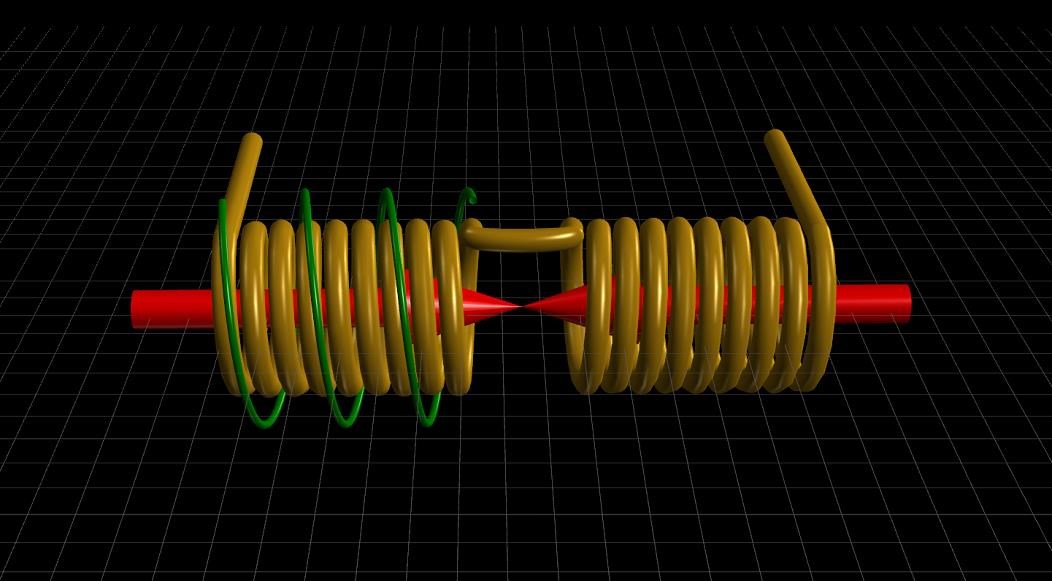
Delayed Conduction is specifically to get the Voltage on the Terminals of your Partnered Output Coils as high as possible in reason! Its the change in Magnetic Field that Creates Voltage, its the Opposition of Magnetic Fields that Pumps Current!
Circuitry can also be employed to delay Conduction on the second Partnered Output Coil.
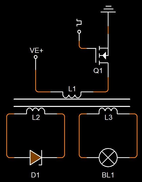
I gave an example of Delayed Conduction here.
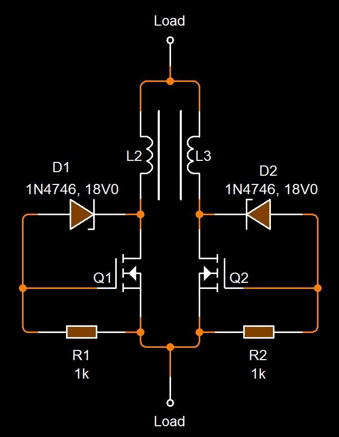
As you can see, the Mosfets will only conduct when the Zener Diodes Conduct, this is rated to 18 Volts.
This means, the ends of the Partnered Output Coils must be at least 18 Volts, before the Coils can power any load!
We have seen this before! This is not new to those that have done the Study!
The MEG Demo Circuit
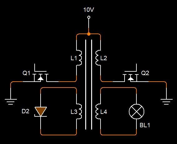
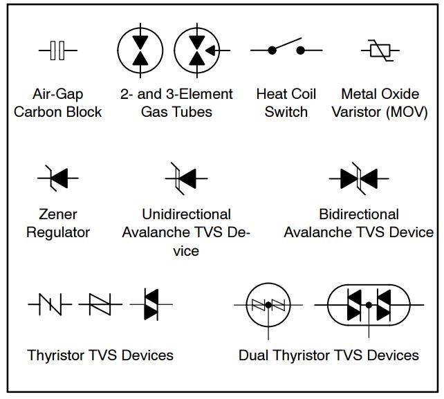
Where D2 represents a Bi-Directional TVS.
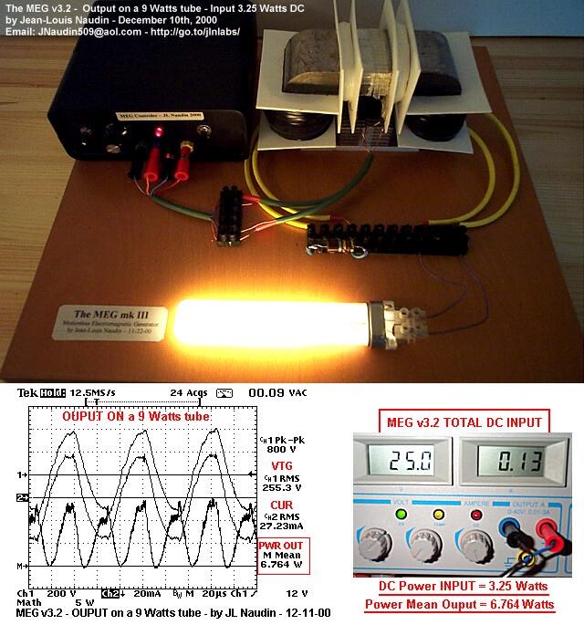
Ref: JLN MEG Replication
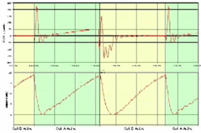
Ref: The MEG Team Data.
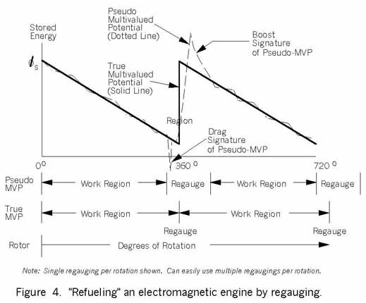
Where the Top Trace represents the Input Channels, and the bottom Trace Magnetic Resonance in the Output Coils, seen as Asymmetrical Regauging.
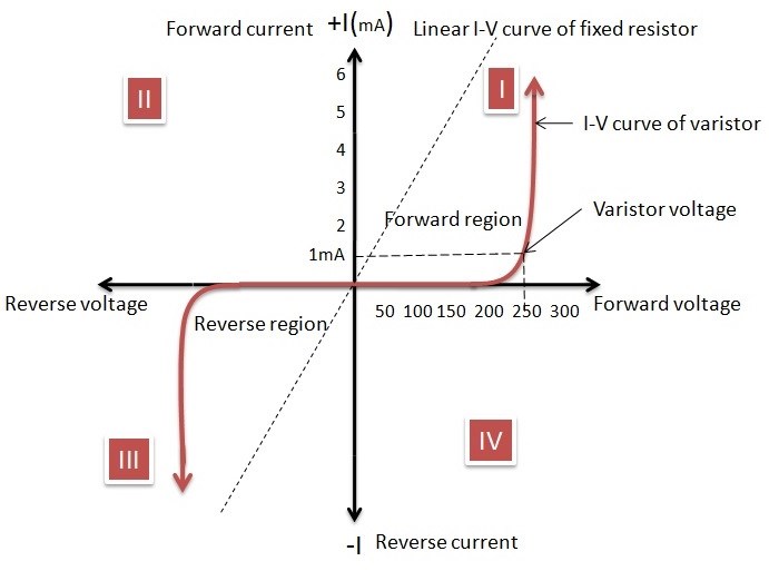
NOTE: JLN used a MOV in his MEG Replication. A MOV has similar Voltage to Current Characteristics!
Ref: JonRB
![]()
Ref: Renesas Datasheet
I want to stress the point of getting the Voltage on the Terminals of your Partnered Output Coils to a maximum without being disturbed. Input Creates a Voltage on your Terminals, then the Input is switched off. Then your Partnered Output Coils Conduct and we Pump Current.
Remember: Some of these Circuits may require an Earth Ground.
Chris


 .
. I try onesmore and so it is much shorter ,is it best to have exactly the 180° or is it better a little of?I hope you dont mean i am a troll.If you want i can delete the other posts.


