A Reliable and Flexible Switching System is second to none, it is the most important piece of Hardware one could have on your bench!
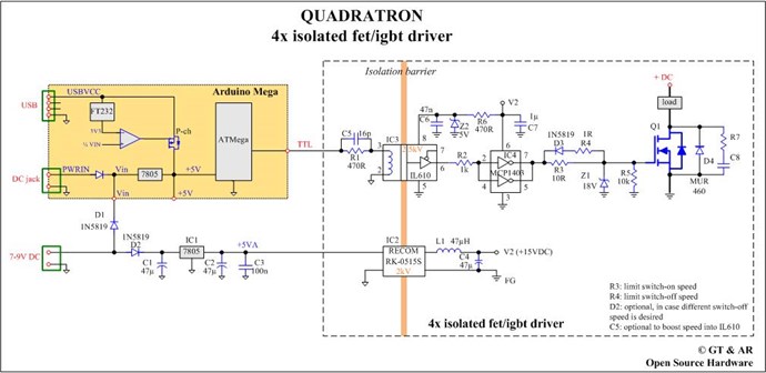
I was lucky enough to share some data with a friend that had worked on this same concept with one of his friends, Back then, the idea was called the: Quadratron
Funny enough TheOldScientist has done some videos on this:
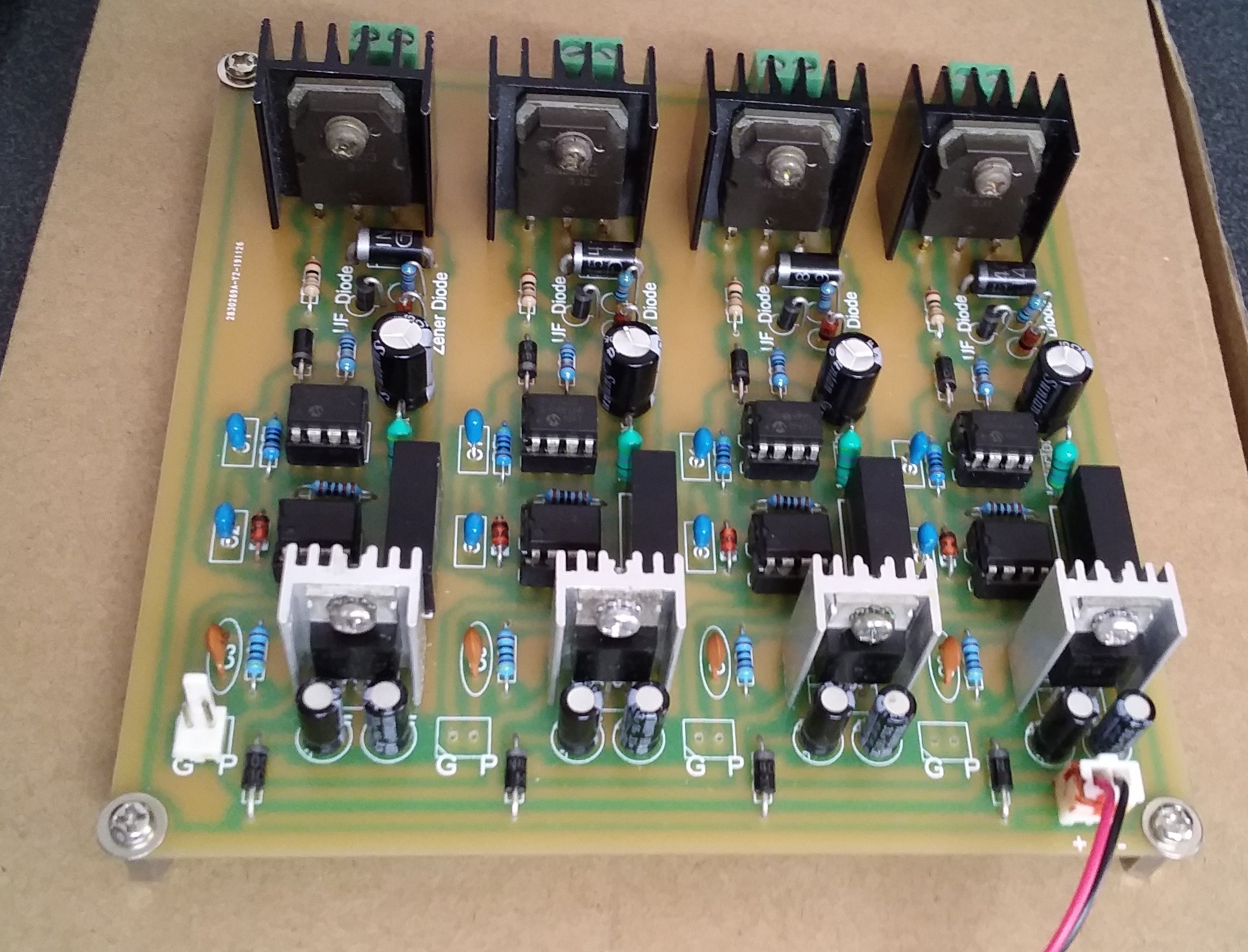
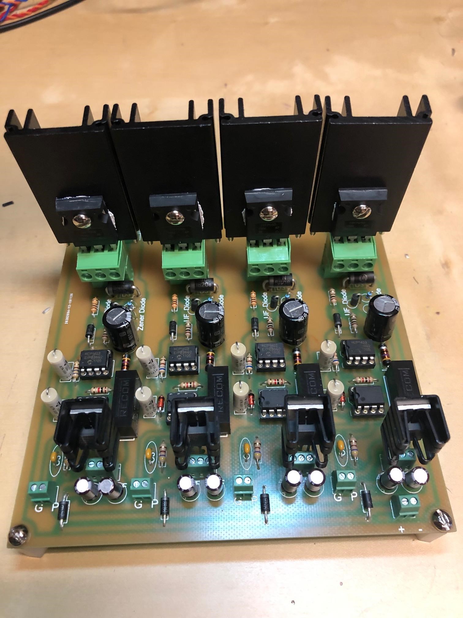
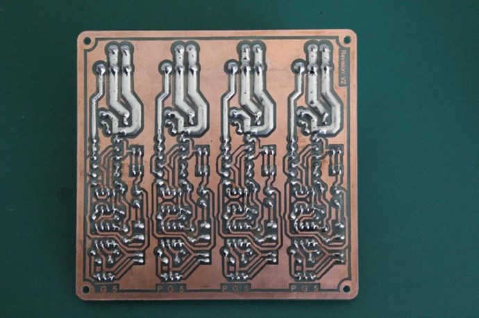
I have also build a few versions of my own inception of the: Quadratron which is now called IPC-quadra
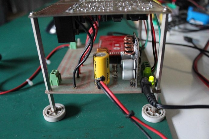
Version One:
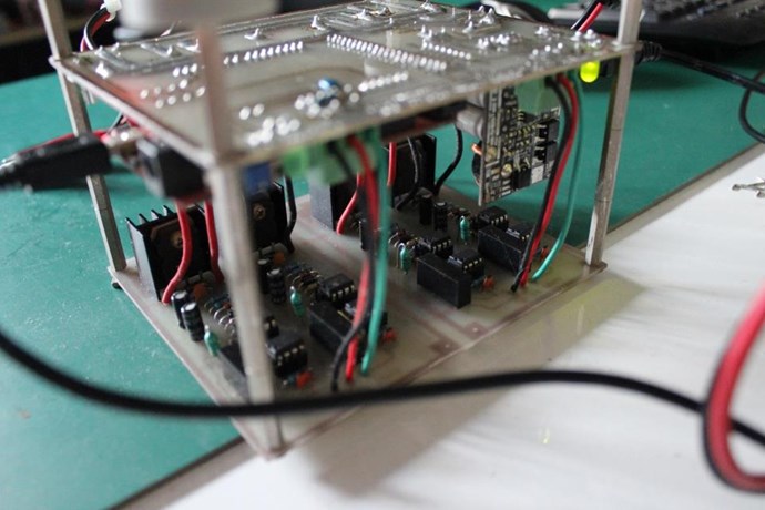
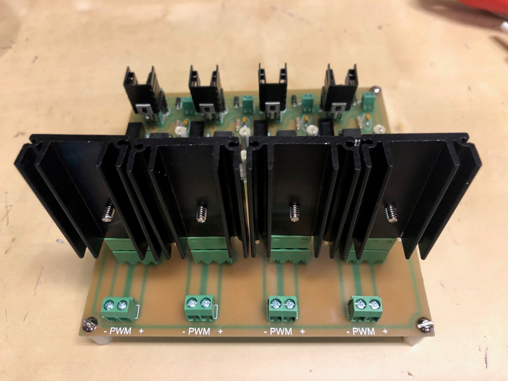
Version Two:
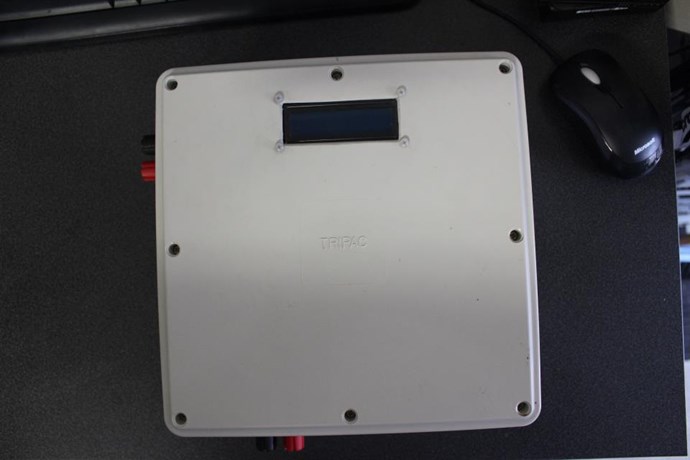
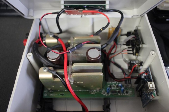
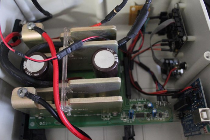
I have another H Bridge I use also, this is not related to the Quadratron. It is a Custom Built, Salvaged from an Old UPS, 3000VA:
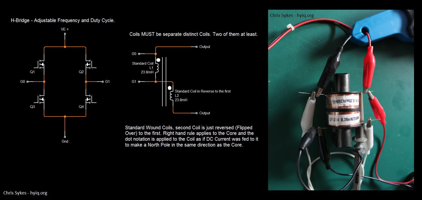
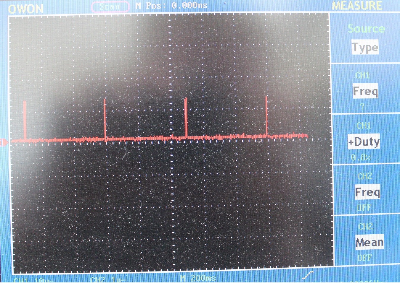
I think it is important to not, this is very handy, but its not a necessity, cheaper and easier options exist. EBay has some good options. Variable Frequency and Duty Cycle are the absolute most important.
High Voltage and Current is not necessary.
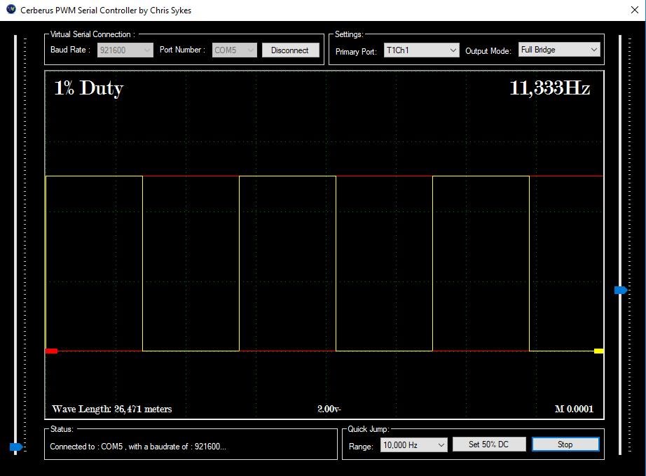
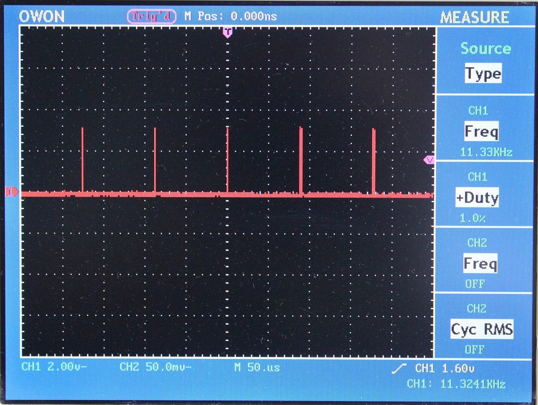
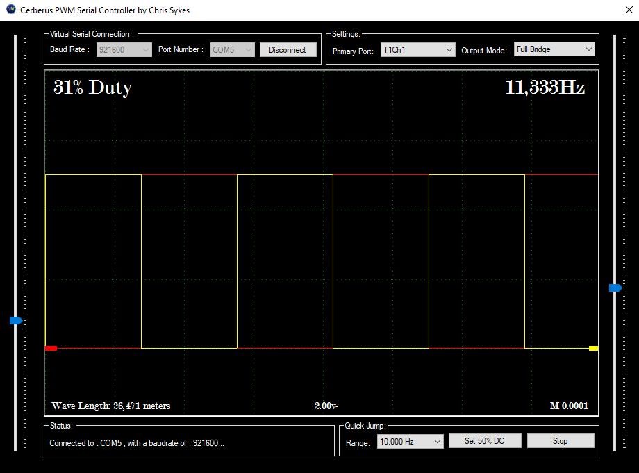
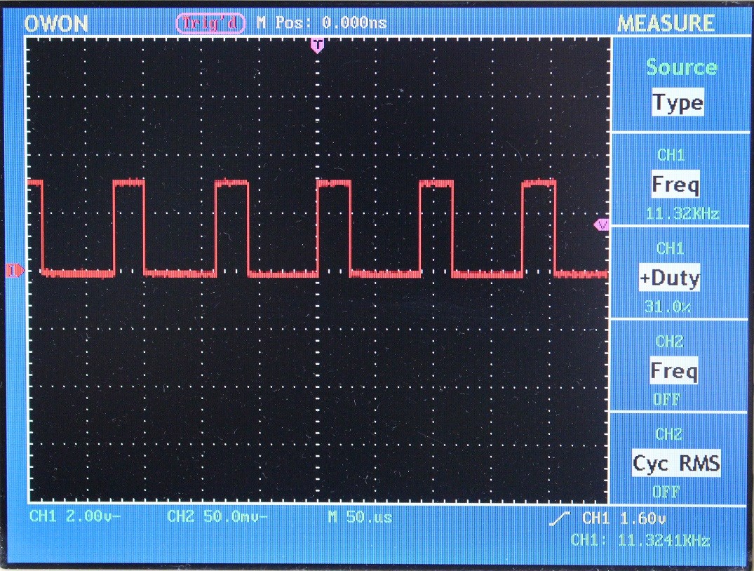
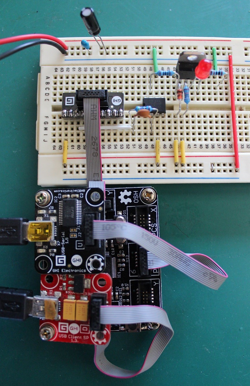
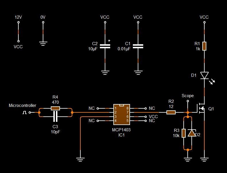
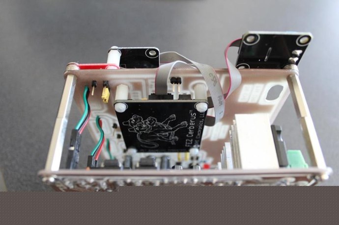
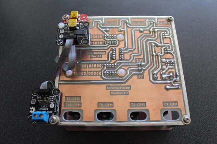
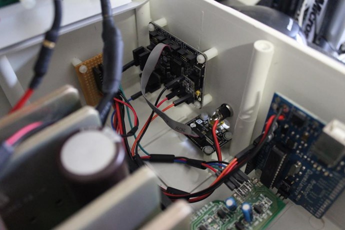
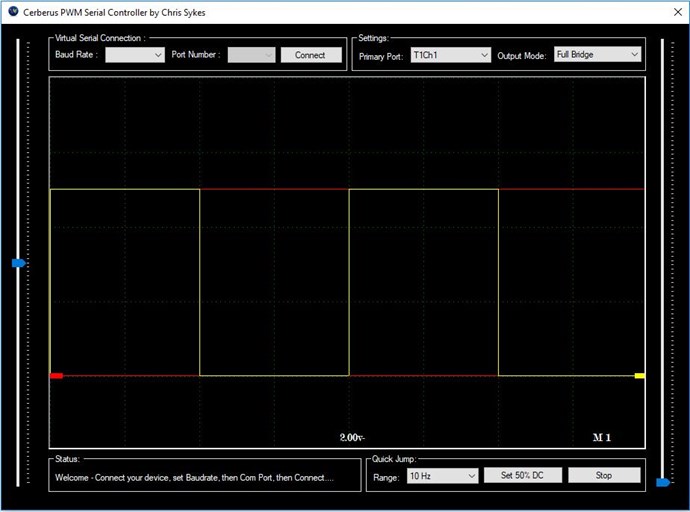
I personally find a Microcontroller is a good cheap option! Easy to use, Plug and Play if you don't mind the pun! I have built all my own software:
I think if we combined our skills, we as a team could come up with a community based project that is better and cheaper than all options presented!
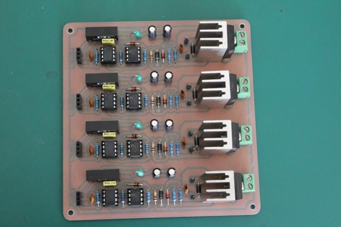
China could do cheap PCB's, We could build our own software!
We could find a cheap Microcontroller.
Let me know if you're keen to look into this!
Chris