Parallel Wire or Bifilar Coil Experiment

  • Topic Is Sticky
  • Poll
  • 8.3K Views
  • Last Post 13 March 2020
I do not understand this Thread?
1 Votes
I fully understand this Thread!
8 Votes
I partially understand this Thread?!
5 Votes
Chris posted this 23 January 2019

My Friends,

In the beginning, cursed with limited knowledge, I fumbled with the terms and diagrams of Floyd Sweet and others. Also taking note of other devices like Paul Raymond Jensen, Lester Hendershot and others, after some time I saw some common themes and base concepts.

Think Simple was my saviour!


Voltage

Voltage is Elementary Charge, separated, creating a difference in Charge Potential on Each Terminal.

A concept requiring Conductance ( G ) = 1 / Resistance ( R )


Current

A flow of Elementary Charge, originally defined as 6.24 1018 electrons per second past point P1 equaling 1 Ampere of Current. Current must be Pumped exactly the same as Water must be pumped to create a flow. Electrons in a Wire have Velocity, depending on the composition of the Wire, it can be close to the Speed of Light.

Also a concept requiring Conductance ( G ) = 1 / Resistance ( R )


Note: The closest analogy to Electrical Energy is Pumping Water through a Pipe!

Note: Kinetic Energy is the elementary motion of a body or bodies. Newtons, force = mass times acceleration.

Ere many generations pass, our machinery will be driven by a power obtainable at any point of the universe. This idea is not novel. Men have been led to it long ago by instinct or reason; it has been expressed in many ways, and in many places, in the history of old and new. We find it in the delightful myth of Antheus, who derives power from the earth; we find it among the subtle speculations of one of your splendid mathematicians and in many hints and statements of thinkers of the present time. Throughout space there is energy. Is this energy static or kinetic! If static our hopes are in vain; if kinetic — and this we know it is, for certain — then it is a mere question of time when men will succeed in attaching their machinery to the very wheelwork of nature.

- Nikola Tesla, "Experiments With Alternate Currents Of High Potential And High Frequency" (February 1892)


Take a length of Wire:


Immerse this Length of Wire in a Sinusoidaly Changing Magnetic Field.

We know and experimentally can prove, the Terminals, not shown, will have an E.M.F, Electromotive Force, or a Voltage will be Induced determined by: E.M.F = -N dΦ/dt

It can be experimentally proven that the Currents and Voltages will have a specific Polarity and Phase that is unchanging between the two Parallel Wires at all points during the Cycle.

It also can be proven that the Currents will be travelling in the same direction at all points during the Cycle. No matter what winding polarity is used - This is the result of the Driven Force Pumping the Current.

At no point during the cycle, do the Parallel Wires Buck each other.

We have seen, some Transformers are wound with bifilar Coils, as a method of doubling the Current with less total wire area:

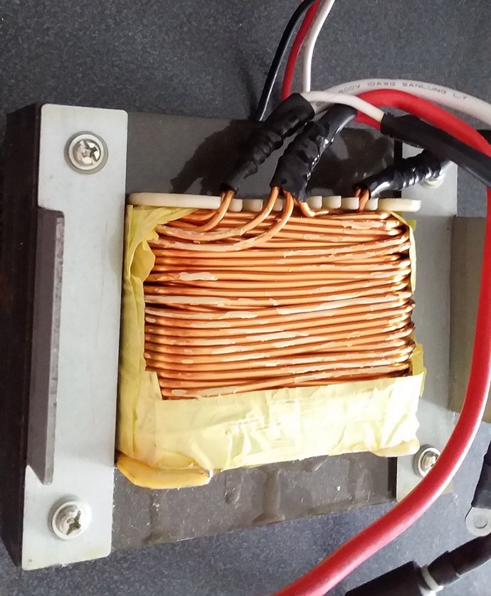


This is not a Natural State for Parallel Wires when a Changing Magnetic Field is present!


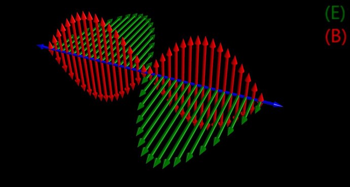
A sinusoidal waveform can be shown to contain Electric and Magnetic individual components at different times:
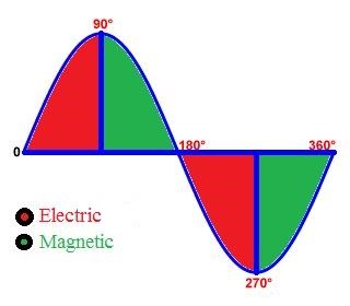


This knowledge is critical knowledge to have and understand. Why? Because we have a means, in every aspect, to simulate an Electrical "Generator" using three things:

  1. A source Magnetic Field changing in Time t. Not yet shown. Area shaded Green above.
  2. Conductors with an Induced E.M.F and as a result potential for Current to Flow.
  3. A means to Pump Current without adversely affecting the Input Source Magnetic Field.


Now what device do we know of that can Isolate Conductivity at a specific point in the Cycle shown above? Most of you no doubt will have an epiphany at this stage.

A Triac is capable of Conducting at a specific Point in the Cycle.


The waveform of a Triac can be tuned, or adjusted to look something like this:
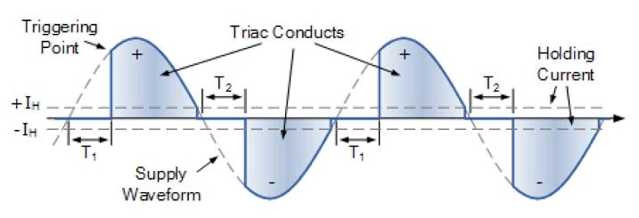


Ironically, Floyd Sweet made use of a Triac, in his hoaxed Magnet Conditioning demonstration.

Note: A Triac is switched using Voltage. It is not a Current detecting device. So depending on ones configuration and if there exists a large Phase Angle difference between Voltage and Current, this may not be the best case method.

Most circuits are designed for a Mains Frequency and Voltage, so, some work to get the Frequency and Voltage you are working at may be required.

Many circuits exist, and many circuits can be employed, but the basic Voltage detection circuit is as follows:
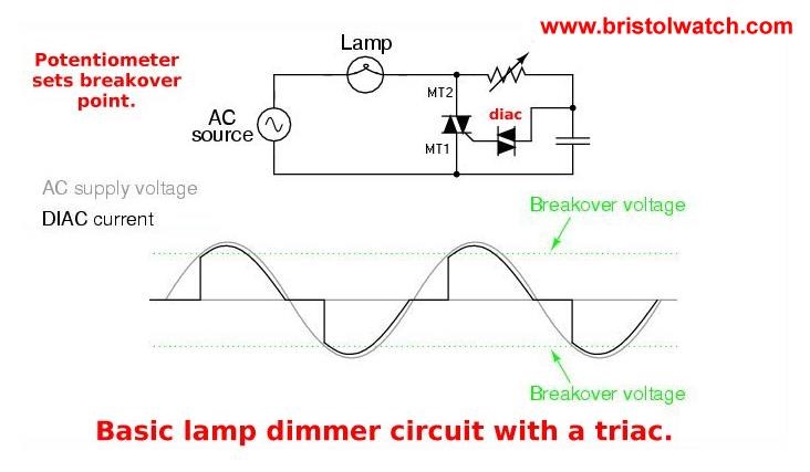
 

Again, do not limit yourself to a specific circuit. However, your goal should be:

  • Resistive Load to ensure Voltage and Current are in phase best as possible.
  • One Partnered Output Coil must not be Conductive during the Electric part of the cycle.
  • The effective Isolation of the Input to Output is effective during the Magnetic Part of the cycle.
  • Learning what the difference in Conduction during part of the Cycle does: Bucking Magnetic Fields.


Remember, I said:

Circuitry can also be employed to delay Conduction on the second Partnered Output Coil.

Ref: How to build your own Above Unity Machine


Some work, some extremely simple understanding of the most basic fundamental things can be achieved by focusing on one thing:

  1. Bring your Machine to life - Let the Machine do what Nature wants it to do!


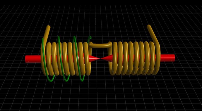
Let it be that the Partnered Output Coils Pump each other! Using Timing to achieve a specific state! Invoke Parametric Excitations of Electric Oscillations. Note, when the Magnetic Fields slap together, we also see an Impulse Pressure Wave! At this point we see a Standing Wave!

Remember what Floyd Sweet said:

If the directions of the two signals are such that opposite H-fields cancel and E-fields add, an apparently steady E-field will be created. The energy density of the fields remain as calculated above, but the value of the E-field will double from E / 2 to E.


If you understand this, and all I have shared in other threads, then a simple circuit to allow your Machine to Live and Breath, will change the world today! Nature wants the Currents to Oppose, so let them, don't force the system to do something it does not want to!

For only a few dollars and an few hours work, one could learn more in this experiment than one may realise!

   Chris

Order By: Standard | Newest | Votes
Chris posted this 26 January 2019

My Friends,

When the Magnetic Fields Slap together, we see the same effect we get in The Mr Preva Experiment, we get Magnetic Fields Buck, Oppose, and the Currents are Amplified, we also get Voltage Amplified, if the Fields Slap together Hard enough.


I ask you, if you wish to make that step forward, this experiment can prove very beneficial!

   Chris


P.S: Your Partnered Output Coils do not have to be Parallel Wires, bifilar Coils. They can be individual spaced Coils, only wired in Parallel. An analogy used, Parallel Wires is to get the idea, the Coils orientation correct.

  • Liked by
  • Jagau
  • ISLab
Jagau posted this 27 January 2019

All these systems operate on the basis of standing and traveling waves.
It is necessary first to catch the motion of particles in the coil.


From a resonant system, which does not require effort from the source, we can produce more energy than we provide.

Don Smith used high voltage at resonance, floyd sweet used motinal E fields with magnets and Tesla used longitudinal waves.

Jagau


Chris posted this 13 February 2019

Fact:

The "Generation" of Electrical Energy, Joules per second, inside the Electrical "Generator", inside an Insulated Copper Conductor, must have, at least Two Magnetic Fields Present, Equal and Opposite. This is Lenz Law.


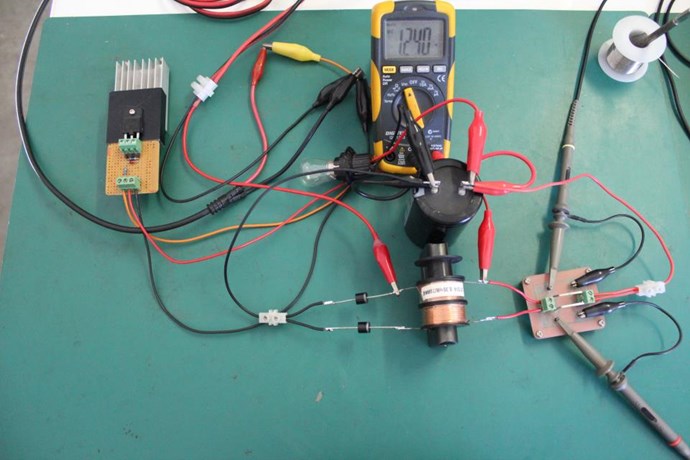
Zanzal kindly shared a video some time back, Coil Shorting vs Coil UnShorting.


Now, there is a message in this video. Look at the facts! Look at what was said and shown in the video.

Zero Load:

  1. Voltage: 12.41.
  2. Amperage: 2.45.
  3. RPM: 779.1.


This gave a Peak to Peak Voltage of around: 76 Volts, 76 * 0.707 = 58.59 RMS Volts.


Coil Shorting:

  1. Voltage: 12.40.
  2. Amperage: 2.40.
  3. RPM: 778.3.


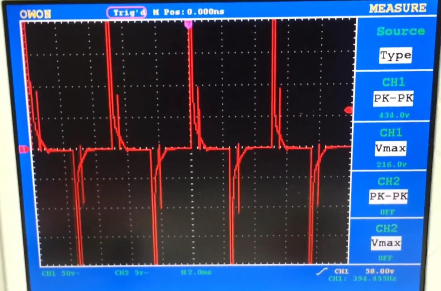
Giving a peak to peak voltage of 192.0 Volts. However because the wave is now no longer sinusoidal we can not use the 0.707 calculation. The 680uF 200V Capacitor is not charged in a particular time frame, an accurate calculation would be hard to estimate. It was written it was "Very slow charging"


Coil Un-Shorting:

  1. Voltage: 12.37.
  2. Amperage: 2.85.
  3. RPM: 751.4.


NOW, we see a very big difference: 430.0 Volts Peak to Peak.

430.0 Volts?

2.23 times more than the last measurement?

5.65 times more than the first measurement?


We surely must see a very important pattern here! It was written: "Very Fast 680uF 200V Cap Charging". The Rotor is slightly slower, so the Time Rate of Change of the Magnetic Fields, on the Rotor, is slower. However we see a much greater Voltage Produced - WHY?

The Magnetic Fields of the Two Coils are Interacting in such a way, via Timing, to Slap together very hard and very fast!


Ref: https://www.youtube.com /watch?v=EUXOZAinUPk


So we have a Standing wave, a very high potential build, but the Coils themselves MUST be forced to Oppose! The Currents in the Coils must travel in opposing Directions! Cap Charges Much Faster! Because more Energy is being "Generated" - Current Charges Capacitors, not Voltage, so it is the Current flowing in the Coils has been dramatically increased - How? By Magnetic Fields Interacting together in such a way that the High Potential gained, and the Interactions of the Coils act exactly the same as we saw in The Mr Preva Experiment, in my thread: Some Coils buck and some Coils DONT, its part of the entire luxury of knowing how this all works.


So, I urge you, especially the builders, Build, replicate these effects, its all possible on a solid state unit, very small in comparison. Replicate variants of YoElMiCrO's Circuits:


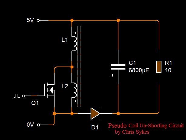
At the time of Zanzal posting the Video, I did post a Pseudo Circuit, to simulate the Coil Un-Shorting convention between two Coils:


Of course looking at this now with fresh eyes, the Diode needs to be on the top rail, to stop the Cap from reverse charging.

Remember, replicate the Effects, then it is very easy to improve on these effects. If you look at numbers, you will fail, its inevitable, because all you see is Failure. Where as if you look for the effects, you can only succeed, then one day, you will look up and say: "No Way!"

Then the numbers will talk!

   Chris

Vidura posted this 13 February 2019

Hey Chris and all I have made the test with coilshortening vs. unshortening with my pulsmotor and came to the same result , I didn't switch at sinepeak, which would be better, but the result was very similar, anyway with the unshortening technique the drag on the rotor was strongest. In my tests there was no sign of excess energy, which would be only possible if the standing magnetic waves can be phased for regenerative acceleration, which is the tricky part of our work, this also applies for transformer devices. But basically a huge potential boost is possible with this approach. Regards Vidura.

Chris posted this 13 February 2019

So:

Did anyone take notice of the Terminal Voltage of 5.65 times Voltage Gain?

This is a trick that's been done many times in History! Andrey MelnichenkoRoman KarnaukhovRuslan Kulabuhov and many others.

Graham Gunderson did exactly the same thing as is explained in my last post:


Now where did that 700 Volt Spike come from? Ah Ha, yes we know! Magnetic Field manipulation, to get the Terminal Voltage up, without having to do anything special that costs us a lot of power to do so!

Take this pseudo circuit:


Yes, the Mosfets have internal diodes.

The terminal marked ( X ) has a signal applied, say at 375 Hz with a Duty Cycle of 3%. It is just enough to get this working.

As ( X ) moves into an off state, the Polarity of the Coils Flips, the diode D1 Conducts, and as this happens, we might send say a pulse train of 1Khz with a 1% Duty Cycle to Q2's gate ( Y ).

Are we going to achieve the same result as we got above? Are we going to see a Voltage increase on the Terminals?

If not why?

   Chris

  • Liked by
  • ISLab
Chris posted this 13 February 2019

Hey Vidura,

Sorry I didn't see your post until I refreshed and reposted.

Hey Chris and all I have made the test with coilshortening vs. unshortening with my pulsmotor and came to the same result , I didn't switch at sinepeak, which would be better, but the result was very similar, anyway with the unshortening technique the drag on the rotor was strongest. In my tests there was no sign of excess energy, which would be only possible if the standing magnetic waves can be phased for regenerative acceleration, which is the tricky part of our work, this also applies for transformer devices. But basically a huge power boost is possible with this approach. Regards Vidura.


Yes you are right!

You will notice, the Rotor speed slowed and also the current went up, at the same time the battery voltage went down. This indicated Load on the Rotor.

This is because of the Shorted Coils. Then at peak, not seen on the scope at the time, the Coils are then Un-Shorted.

Remember the diagram we have been looking at:


Green is the GO part. We must not load the Input, the Red part of the Cycle is as Don Smith told us: "A Heat Death"


When we don't Load the Input, we can let the Input do its work.

Then we can make the Partnered Output Coils do their own work, as an Electron Pump. Accelerating Electrons Using Magnetic Fields as a Pump!

   Chris

Chris posted this 13 February 2019

My Friends,

I want to point out, if you're waiting to buy these machines from market, it will never happen. At least in the near future! 

The only way is to learn and then build your own. I have no intention of selling machines, I know I will not get that far! Please, Build your own.

I have updated the above Quotes as required.

   Chris

  • Liked by
  • Vidura
  • ISLab
Chris posted this 13 February 2019

My Friends,

On the same topic, of Timing, to increase the Voltage Potential on the Terminals, using the Magnetic Field Interactions between two Coils.

We find that we need a method to do this efficiently, but also at the right time. Sometimes these Coil Interactions are very hard to see what's going on!

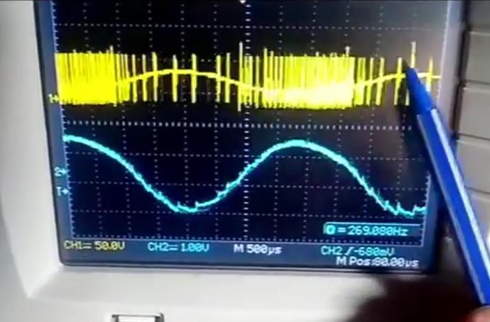
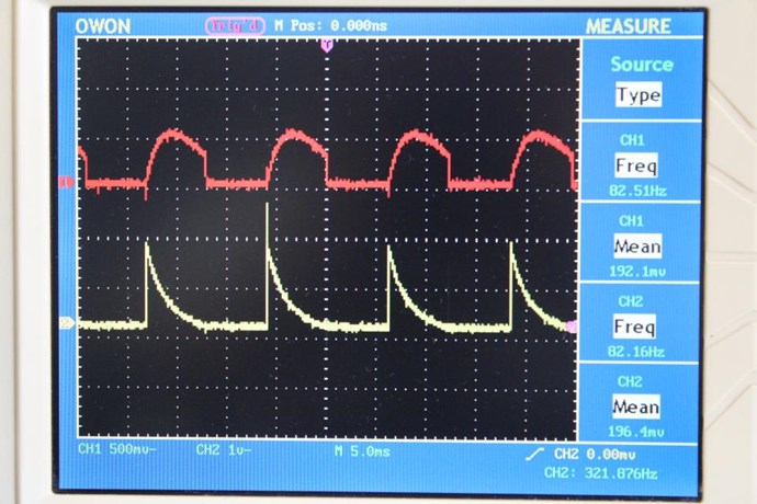
Akula gave us scope images like so:


All from a little circuit like so:


Remember, this was a Circuit of Andrey Melnichenko! Not Akula, Akula replicated this work!

When the Fields Slap Together, we see Magnetic Interactions that first of all increase Potential, Voltage, and then as a result, Current is also increased because:

I = V / R


By increasing Voltage ( V ) by 5.65 times, as in the above example, we also increase Current ( I ) by 5.65 times because Resistance ( R ) stays the same!

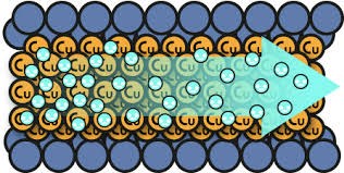
Ohms Law, its real and it does work as is stated when dealing with Electric Phenomena. Electric Phenomena is completely subject to Magnetic Fields! Take a single wire:


Where, Charge ( Cyan Ball ) directly associated with the Copper Atom Cu, is Charge under Acceleration.


Listen very closely:


Now, from Floyd Sweet:

The current and voltage initiating fields are in such a direction to either accelerate or decelerate the rate of flow of charges depending on the applied polarity and voltage amplitudes.

As polarity may be maintained constant, that polarity of acceleration should be chosen so charges move at faster rates, lowering copper duty factor, at the same time opening the gates wider so more coherent field entities may enter for the conversion process.

It’s obvious, we have a self-regulation machine whose inherent conservation to the nth degree.


When the Magnetic Fields Oppose each other, which is defined by Lenz's Law, Current is Pumped, its a function of Loading the Coils in the right polarity as is pointed out.

Those of us that have been around for a while will already know most of this stuff.

The point is, the Voltage Potential on the Terminals is Important and it is required to be increased, all by Faradays Law of Electromagnetic Induction.

   Chris

Chris posted this 15 February 2019

A Coil with no Voltage Potential can carry no Current.

Is Current "Generated", or is Voltage "Generated"?

What is the term "Generating", attempting to define? What is "Generation", in the terms of an Electrical Generator.

We have such a vague view of what's truly going on. Voltage can be present on the Terminals of the Coil in a "Generator", but we can have zero Current! Current only flows when we load the Coil! So a logical mind must give the two quantity's a very distinct separation!

At the same time, they have a close relationship.

A change in Current can "Generate" a Voltage. The faster the change, the greater the Voltage "Generated"... Current is analogous to the Magnetic Field.

A Current can only flow if there is a difference in Voltage on the Terminals. The greater the Voltage Potential, the greater the Current. Seen as an Ohms Law equation: I = V / R.

Current is a quantity that's defined as Electrons per second, so if one wanted to fill a bucket with electrons, the Tap would need to be running for as long as is required to fill the bucket. 

This means the Pump must be running, and as long as there is a Voltage Potential, there can be a flow of Current.

So, Current is a quantity that requires Pumping, this is seen as Lenz's Law, equal and opposite, however, nothing states that this equal and opposite is required to oppose your Input! This is a false assumption we automatically infer.

An inference which is our own limitation in Science.

I have proven this to be a false assumption here: Some Coils Buck and some Coils DONT

So, if we have a Voltage, we switch in the Pump at the right time, then we Pump Current as long as there is a Voltage and the higher the Voltage, the longer the Pump can run due to the fact that the pump is under pressure as long as there is a Voltage:


Ref: https://www.youtube.com /watch?v=EUXOZAinUPk


Why is the young man running? What happens to him next?

Simply, our Pump is Opposing Magnetic Fields! Partnered Output Coils.

   Chris

Chris posted this 15 February 2019

My Friends,

This concept of "Parallel Wire" is important.

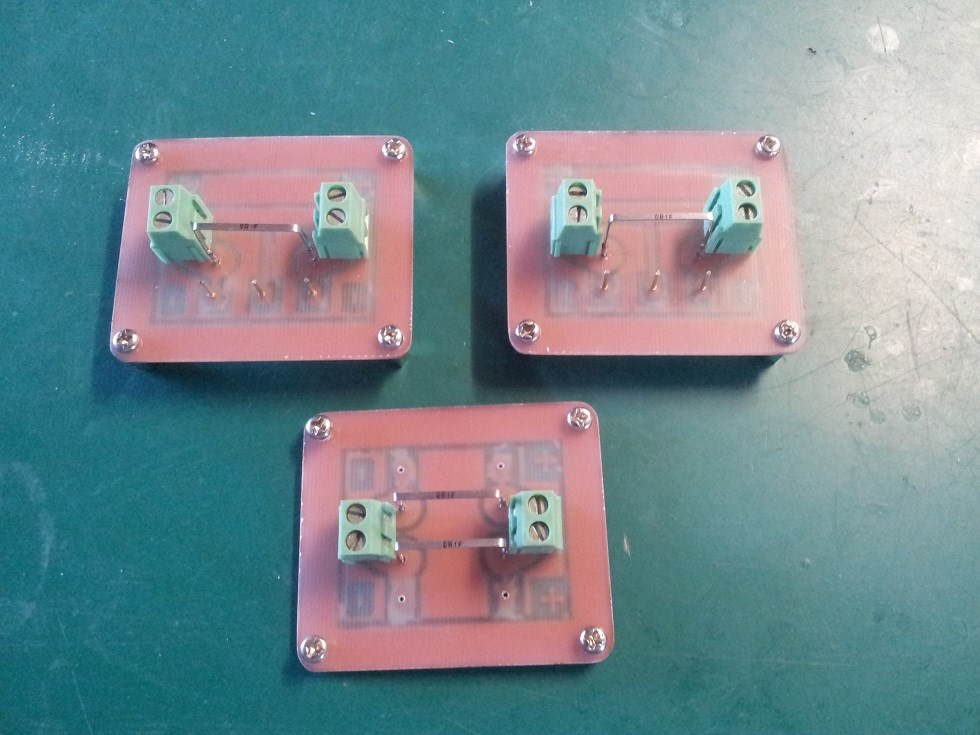
I showed in my thread: Some Coils Buck and some Coils DONT that the Currents, measured in a Parallel manner, did not have to be the same. Using the bottom Measurement Block/PCB:


Which can be thought of as:


Parallel Wires of length X.

Yet the Voltage and Current can be in very different directions depending on the situation created by us, this is a case of:

Two men pushing their Carts, one with 100Kg's of Apples, one with 100Kg's of Oranges, one at the top of the hill, the other at the bottom of the hill.

The Carts are connected via a huge rubber band at the top of the hill via a pully (Lenz's Law)

The man at the top of the hill lets go...


Bodies in motion, Kinetic Energy, Force ( f ) = Mass ( m ) x Acceleration ( a ) ( f = m ⋅ a )

Remember what the greatest man that ever lived said:

Ere many generations pass, our machinery will be driven by a power obtainable at any point of the universe. This idea is not novel. Men have been led to it long ago by instinct or reason; it has been expressed in many ways, and in many places, in the history of old and new. We find it in the delightful myth of Antheus, who derives power from the earth; we find it among the subtle speculations of one of your splendid mathematicians and in many hints and statements of thinkers of the present time. Throughout space there is energy. Is this energy static or kinetic? If static our hopes are in vain; if kinetic — and this we know it is, for certain — then it is a mere question of time when men will succeed in attaching their machinery to the very wheelwork of nature. - Nikola Tesla "Experiments With Alternate Currents Of High Potential And High Frequency" (February 1892)


I want to make a point of saying, our Input only creates a Voltage Potential on the Coils. This Voltage Potential can be manipulated, via switching, to create a greater Voltage Potential. If you like, a Transient or Spike. This is entirely a trick or an artefact of the switching Potentials shown above:


***   5.65 times the Voltage of the initial Change in Magnetic Field   ***


Greater Voltage Potential can then be used to simulate the Magnet falling through the Copper Tube, as we have a Magnetic Field, and its Changing in time:


NOTE: The Copper Tube is our Output Coils, Partnered Output Coils, each Coil, via switching, can be Shorted ( Loaded ), as shown in the Copper Tube Experiment above. One man s Cart going up the Hill, the other going down the hill:


If the Copper Tube has a cut all the way down one side, the Copper Tube would not exhibit the same reduced speed effects on the Magnet. This is open Circuit, there is no effects of Lenz's Law. This Experiment is shown in a slightly different way here:


What I am pointing out, again, its just a trick, the greats have used to increase the Output Voltage Potential. E.G: Andrey Melnichenko Flashlight Circuit:


Its one way, not the only way.

   Chris

  • Liked by
  • cd_sharp
  • ISLab
Chris posted this 16 February 2019

My Friends,

This thread is soon becoming one of the most important threads here on this forum.

Time ( t ), time is a critical factor, it is a dependant factor in Electrical Energy; which is defined as Joules ( J ) per second. One Watt Hour ( Wh ) is: Joules ( J ) per second x 3600, because there is 3600 seconds in one hour. So, one Watt Hour ( Wh ) is equal to 3600 Joules ( J )

So, the "Generation" of Energy, is time dependant.

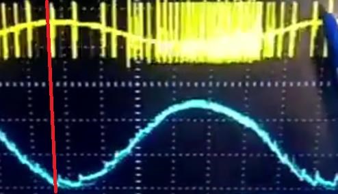
Lets observe this image in some detail:


You can see, we have Triangles in the Blue Waveform, clearly seen:


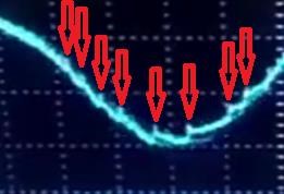
In the Blue Waveform, we see there is a line up of the Spikes, I have marked this in Red. These Triangles are the same as I have pointed out above:


This is where the Coils build up a Potential, this "Generates" Current, the Pump, the Tap is open for a Flow. Currents are Equal and Opposite. Lenz's Law, a Natural State, a state that Nature requires for a System to come back to Equilibrium. A closer look:


Its hard to see in a Sinusoidal System, DC Pulsing is a lot easier to see what's going on. Lets listen to one example:


Lets look at two examples:

Ref: Tinman ( Bradley Richard Atherton ) - The Rotary Transformer.


Ref: Graham Gunderson - The MIT.


Many times we have seen examples of this Triangle Waveform, its the same as I have described here:


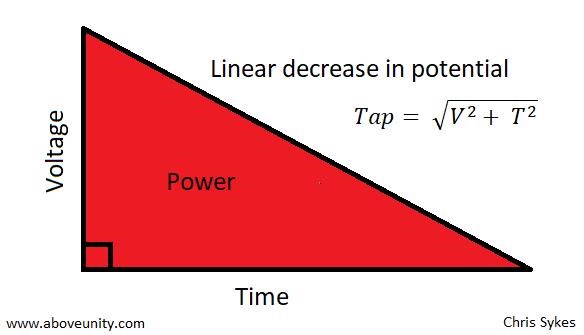
As long as we have a Voltage on the Y Axis, we have a Pump that can Pump Current for the time indicated on the X Axis.

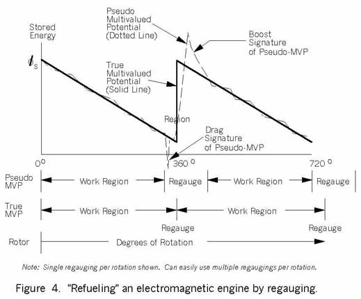
All we need do, is create the Voltage, its Asymmetrical Regauging, described as: 

Ref: Tom Bearden - The Tale of Rajah


Right here we see not just one, but four examples...

   Chris


P.S: Some of my videos have been removed from YouTube and there is no explanation why.

  • Liked by
  • ISLab
Chris posted this 16 February 2019

My Friends,

It makes me laugh!

While the Super Numpty's else where debate for days on end: "Dose it take power to create a magnetic field", here we are actually showing, critical, key information on Energy Machines! Critical, Key information, you can only find here.

Moving on:

A piece of Insulated Copper Wire is an amazing, very advanced piece of machinery! Electrical Energy can not pass the Insulation Boundary, yet the Copper Conductor is among some of the most Conductive Elements we know of. Copper ( Cu ), is the standard at which we base our Conductivity standards:


Copper is the standard by which electrical materials are rated and conductivity ratings are expressed as a relative measurement to copper. These ratings will frequently be expressed as "28 IACS". IACS is the abbreviation for International Annealed Copper Standard and the number preceding "IACS" is the percentage of conductivity a material has relative to copper, which is considered to be 100% conductive. This does not mean that copper has no resistance (is 100% conductive in an absolute sense), but rather that it is the standard by which other materials are measured. The higher the % IACS, the more conductive the material is. This standard refers to a pure, "standard" copper having a resistivity of 1.7241 microhm-cm at 20°C (68°F).

Ref: https://www.bluesea.com/resources/108/Electrical_Conductivity_of_Materials


Remember, Conductivity ( G ) is equal to 1 / Resistance ( R ), Resistance is defined as the ratio of Voltage ( V ) to Current ( I ) through a Resistive Element, just pointed out, the Conductance ( G ) is the inverse of the Resistance ( R ). Mathematically: 

R  = V / I

G = I / V = 1 / R


For a wide variety of materials and conditions, V and I are directly proportional to each other, and therefore R and G are constants (although they will depend on the size and shape of the object, the material it is made of, and other factors like temperature or strain). This proportionality is called Ohm's law, and materials that satisfy it are called ohmic materials.


In our application, we use Strain, Stress, Pressure, thus Resistance ( R ) is not a constant! So we have a: "Differential Resistance", actually, Impedance changes in Time. This is my: Reduced Impedance Effect.

Strain, or Stress is something we have been told about:


We all know already, Magnetic Fields Oppose, Current Adds, the Current is a Standing Wave of at least twice the singular potential. We are pumping the Current, we have an Electromagnetic Pump:


Where, Charge ( Cyan Ball ) directly associated with the Copper Atom Cu, is Charge under Acceleration.


Using the trick explained in the above posts, 5.65 times, it can be very much higher.

Remember, it is the Change in the Magnetic Field that "Generates" a Voltage.

   Chris

  • Liked by
  • Vidura
  • ISLab
Chris posted this 17 February 2019

My Friends,

I get the feeling there is a bit of confusion here?

An experiment:


OK, a very simple circuit. Inductor L1 is being switched at a rate of 100Hz and 50% Duty Cycle. Capacitor C1 is charges by Inductor L2, through the Diode D1, however we have the Inductor L3 shorted across Capacitor C1, so a logical assumption would be, the cap will never charge, its being discharged at a faster rate than it is being charged.

  1. All coils are exactly the same.
  2. All coils have the same Coupling and Mutual Coupling to each other.
  3. We can change Frequency and Duty Cycle.


The goal is to keep a constant charge on the cap at as high a Voltage as possible.

Can this be done?

   Chris

Jagau posted this 17 February 2019

My friends

 there is a verifiable fact:

At the time of the abrupt disappearance of the electric and magnetic field in a set of coils in P.O.C.

at the zero point between the two coils there is a phenomenon that we are looking for, there is a pumping effect coming from the environment (aether) and lasts only a fraction of a second,

the frequency at which the pump works is intimately linked to the resonance frequency.

The result of several experiments proves this fact.


Jagau

Chris posted this 17 February 2019

My Friends,

Regarding the above Experiment,  I will give you a Clue:


The Frequency is: 203Hz at 50%Duty Cycle. 1 / 203 = 0.00492610837 seconds which = 1 / 0.00492610837 = 203.00Hz, at 1ms per division, we see: 1,2,3,4,5 nearly 5 divisions, which equals: 0.005. The reading of: 3.40KHz is not the Run Frequency.

@Jagau - I agree, it is easy to show. Coils do work, when Magnetic Resonance is found, and the Terminal Voltage is sufficient, amazing things happen! Thanks for sharing my friend!

   Chris

  • Liked by
  • Vidura
  • ISLab
Chris posted this 17 February 2019

My Friends,

Another shot, what do we see?


Marked in Red, this is almost 0.5 of a Volt, this is Diode Conduction.

Yellow trace is On time. Red Trace is the Ve+ on the cap, it is currently reverse charging, but why? Have I messed up the circuit. Its a tiny bit different but not much. I will let you figure it out.

Triangles, on charge and also on discharge, why and how?

Does this make any more sense now:


I hope you can see the correlation, the how's and whys. If not, replicate what I am showing you, look for these effects and use what I have posted here to increase these effects.

All from this little Circuit, or a slight variant of it:


The challenge to keep a constant charge on the Cap: Successful

So, how can I keep a -1.3 Volts mean on the Cap when the Cap is shorted? What's going on to keep a Capacitor charged when it is effectively shorted?

   Chris

Jagau posted this 17 February 2019

Hi Chris

In my first assertion I forgot to mention that the ferromagnetic material has a direct function in the result

with an aircore it does not work.

 And in your question: the diode has a very low voltage conduction in the other direction,

an avalanche effect can occur in the diode.

Jagau

Atti posted this 17 February 2019

There are some thoughts on the shape of the above layout sign. Obviously, it does not matter where the shape of the signal is measured.
What we relate to. Not only this, but also in another arrangement, is this measured signal shape. For parametric amplifiers or ferro-resonance transformers, if the diode capacitor is coupled. The shape of the pumping signal is added. Or the load.
However, the following question arises:
- Does the power supply have less power or more?
- Does the recorded power fall or decrease?
-what's next ?

Chris posted this 17 February 2019

@Jagau

Yes a core is required, at least this is what I believe for maximum coupling of the Coils. If the coils are not coupled to each other properly, then this effect is much reduced.


@Atti

Very nice replication! Thank you for taking the time to look at this!

What Cap voltage were you able to sustain?

"What's next" = probe your currents, see what your currents are doing.


   Chris

  • Liked by
  • Jagau
  • ISLab
Chris posted this 18 February 2019

My Friends,

So, we know and can see, it is the Change in Magnetic Field that creates an E.M.F or "Generates" a Voltage.

We saw above, a Tension is held on, shorted, the Coils in the Video, they are shorted until half Cycle. Then they are un-shorted, we see the Coils are subjected to very large Voltages ( 5.65 time more ). Again here:


I have made reference to this for a long time, many here know this already, its fairly basic Electronics, the problem is, most everyone is trained to get rid of it, not explore and investigate this, one example is this video:


An Electrical Engineer that knows what he is looking at, but is trained to ignore and get rid of this problem called parasitic-Inductance. We see it everywhere:


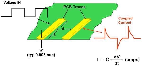
  • What's the Title of this Thread?
  • What do we see in this Image?
  • What's the Result of Current changing very fast in Trace One?
  • What's the Result of a Short across Trace Two at Peak Voltage?
  • What's the Result of a Short, at peak Voltage of both Traces?

If you use common sense, with what I have done the best I can to share, then a much larger picture, I hope will be forming! I have tried to explain in this video:


You need to catch the wave, with clever timing and Magnetic Field Effects, building a Voltage that can then be used to put the Magnetic Field under Pressure, you can Pump Current, and the result is a Sawtooth Wave form.

Again:

The Thread: Impulse Pressure Wave, particularly Jagau's post in the pdf document on Ferro-Resonance, also describes these effects.

Ref: My Post Here.


I don't like the term "Ferroresonance", but I do want to be as accurate as I can.

Let the System do what nature wants it to do, catch the wave, let the Currents Flow in reverse. Bucking, creating a Voltage Potential that we can hold onto for as long as we can.

The Impulse Pressure Wave thread describes some of what's going on here.

In The Mr Preva Experiment, the question I asked: How do we get the Voltage Up? Why so much of a drop?

You know now, how to do it.

   Chris

  • Liked by
  • Jagau
  • ISLab
Chris posted this 18 February 2019

My Friends,

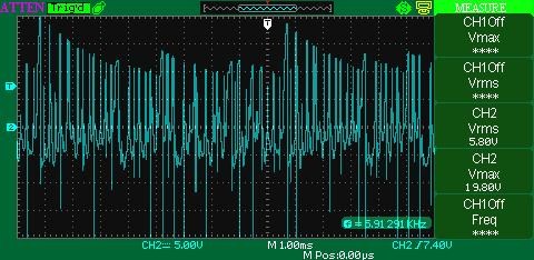
Every single recent Above Unity Machine recently seen shows Spikes on top of Waves, four examples I have shown on this thread alone.

Ask yourself:

  • What is the Spike doing?
  • Why on top of a wave?
  • What is achieved by introducing a Spike to an existing waveform?


I have given you the answers:

  1.  A CHANGE in Current Creates a Voltage / E.M.F.
  2. The Mr Preva Experiment is not Above Unity because too much Voltage is lost.
  3. I have stated: "You need to get the Voltage Up".


In Two Parallel Wires, If they are wound into a Coil, on a Former, they are caring a Current. This Current is a Driven Current. Drop ONE of the Coils Conductivity, with a reverse Diode, at peak Voltage - Watch the Transient Voltage Created as the Currents Flip very Fast.

Remind you of the very fast CURRENT FLIP of another device?


It should!

   Chris

  • Liked by
  • ISLab
Chris posted this 18 February 2019

My Friends,

A Background: An Existing Waveform gives Tension on the Wires, where Current is flowing. This we saw in the above video, seen again below:


These Coils were shorted until Peak Voltage, a Short is equivalent to loading the Coils with a Zero Resistance Load. This means maximum Current is Flowing in the Coils!

Then, by Un-Shorting the Coils into a Load, a Delay in Conduction, The Coils are then forced to move into a Natural State. The Currents Slapping together, into each other, vary fast! Several hundreds of Nanoseconds!

We can see, from top Arrow to Bottom Arrow, a full Flip in Current Polarity:


The Coils, now one Negative Current one Positive Current, during this process, we see a large Voltage gained: 5.65 times the initial Voltage in the above Video, very simple...

The Currents are then the same as The Mr Preva Experiment.

   Chris

  • Liked by
  • ISLab
alohalaoha posted this 18 February 2019

Bucking effect has threshold due to magnetic coupling and other Etheric properties.

It means with low power excitation you will get nothing.

Also bucking effect has shown yourself with aircored coils. Again he has threshold, you need to rise power excitation.

Make high inductance coils, with as high as possible mag.fields. 2-3 coil windings is not enough. I am prety sure that effect also exist in nano scale, but you need DSO woth 500uV vertical resolution to verify this.

There have been experimental results of 34 times AU. It means with 24V pulse you will get 800V hv pulse when all conditions are meet.

Again coil geometry affect bucking coils coupling. They need to be free movable for the 1st time untill effect has caught.

Good luck at hunt for the blue bird.


  • Liked by
  • Chris
  • ISLab
Chris posted this 18 February 2019

Aloha is correct,

A certain Potential must be reached. But this potential reached must be on the Output Coils.

I point out again:


Where the Red area is Power Output, as Voltage decreases, the Current also decreases, Voltage and Current are in phase so V x I = P = Joules per second = Tap where the Voltage Potential is the catalyst for Current to be pumped, to flow.

Again, this is not the only way, but is perhaps the best way to learn.

   Chris

  • Liked by
  • ISLab
Chris posted this 19 February 2019

Graham Gunderson also explains:


   Chris

  • Liked by
  • ISLab
Chris posted this 20 February 2019

It is amazing, when we let the Tension go, by a Conduction Disruption, we get:


Parallel Wires Buck. It is their Natural State. They oppose when Electrical Energy is "Generated", but the Voltage must be greater then your initial Voltage.

We have covered this before, The Lorentz Force.

   Chris

Chris posted this 21 February 2019

I hope all wishing to learn and build these devices reads this thread. It is a very important thread, containing a lot of very important bits of information.

Again, I don't like the term, however the definition for Ferro-Resonance is:

Ferroresonance or nonlinear resonance is a type of resonance in electric circuits which occurs when a circuit containing a nonlinear inductance is fed from a source that has series capacitance, and the circuit is subjected to a disturbance such as opening of a switch.

Ref: Wikipedia


Circuits, pseudo circuits, all of which contain value. The world is in your hands:


Oh, don't forget to vote, lets see how well you understand this thread.

   Chris

  • Liked by
  • Jagau
  • ISLab
Jagau posted this 21 February 2019

Hi Chris


100% agree with your new definition, the words ''openning of a switch''  makes it more refined.

p.s. i dont see any button to vote?


Jagau

  • Liked by
  • Chris
Chris posted this 21 February 2019

Hey Jagau,

Its not my definition, its the one from Wikipedia, I have shared before here. Also mentioned many other places: here, here, here and here, and others...

The document you shared is very good.

Votes at the top of the page.

   Chris

  • Liked by
  • ISLab
Chris posted this 21 February 2019

My Friends,

I want to put my explanation out there of how I found this technique.

Many years ago I started a Thread: Reliable and Flexible Switching System - we also have the same thread here, I don't know why I did not link to it, I normally do. The Thread here: Reliable and Flexible Switching System 

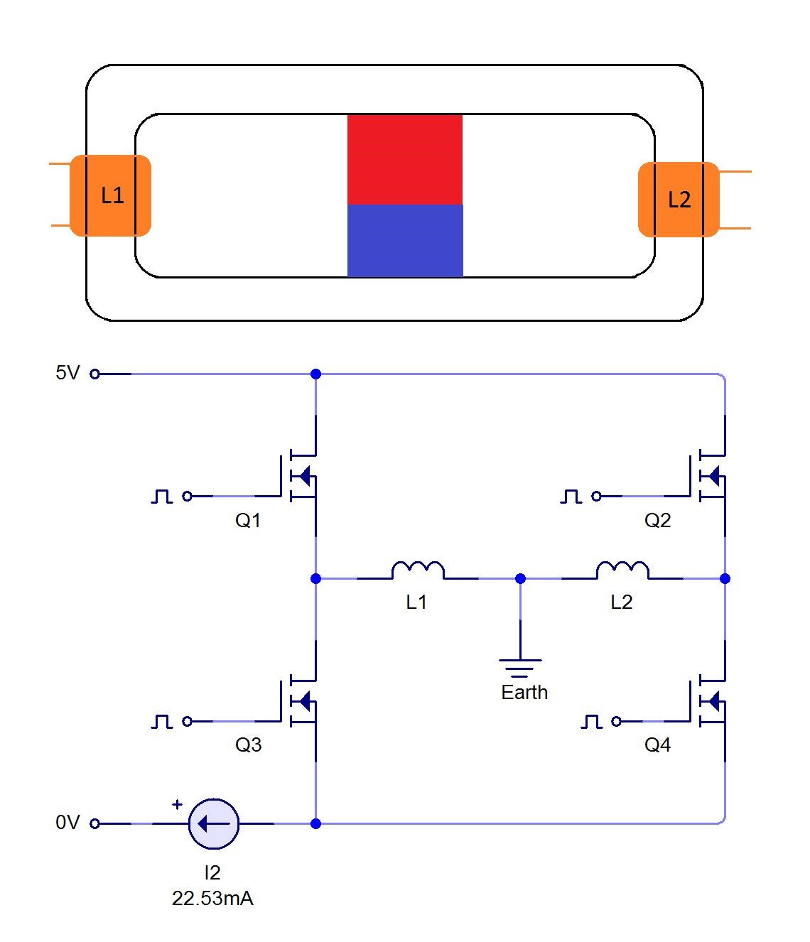
My builds of the H-Bridge had problems. I was not switching properly at each half cycle, I have a coded Microcontroller that was not sending the correct , or at least the expected clean switching that the Electrical Engineering community expects. So one will get different switching times something like:


Where each signal should be at the same time.

So, my H-Bridges were giving me what is defined in the above quote. A chopped, un stable switching in the system. Even on the Input, I saw effects on the Output. A situation that took me some time to understand. I have shared an example with you before:


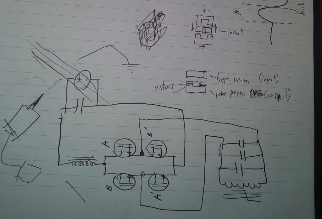
Some of my Notes:


I think I have found a way to switch Flux where it becomes resonant at a particular frequency and at resonance uses very little current!

5 Volts Input, Duty is 50%

My resonance Frequency is: 1.208KHz

When in Resonance, it gets very noisy - Before Resonance I use Current, it drops off as I move into Resonance. My meter shows no Current draw, no milliamps

I have a sensing Coil on one leg - Voltage on the Coil goes up showing higher Voltage at resonance as one would expect

Input Voltage becomes nearly Sawtooth, Triangle Wave - but is in-fact Square, H-Bridge Switched DC

*** Found Oscilloscope Earth Clip Lead to Ground is causing effect!
Measured 44.1 ma going to Ground.
Measured: 22.36 ma into Circuit.


The cause of this resonance was a Switching that was not Clean it was Broken.

So, erratic Switching, on top of an already taught tension, creates Transients that we can use.

   Chris

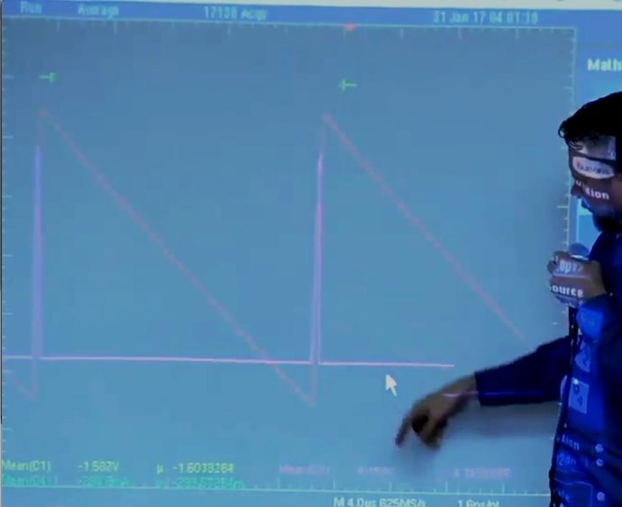
Chris posted this 24 February 2019


Truly, if you understand what I am saying in this thread; the world is yours:


One of my videos I have made correlates to this thread:


Yes, I deliberately showed the Timing difference there. Think Reverse!

   Chris
  • Liked by
  • Wistiti
  • ISLab
Chris posted this 24 February 2019

My Friends,

If you have followed, carefully, you will now understand some very important things!

The Coil Un-Shorting Video is a gold nugget, missed by most that do not understand the significance, however, a technique that has been used by many before as was pointed out!

Take our Parallel Wire:


It has been immersed in a Sinusoidally changing Magnetic Field. As was pointed out, the Parallel Wires will carry the same Voltage and same Current at all times if the Driving Force is maintained, but also if the Parallel Wires Tension is not interrupted.


Your Goal

Should you choose to accept it, is to carefully, at very low voltages:

  1. Maintain the Tension on both Wires.
  2. Interrupt the Conduction on One Wire at peak Cycle.
       Note: Both Wires are your Output Coils: Partnered Output Coils.
  3. Monitor the action, Voltages and Currents, of the Parallel Wires while Loaded.


In essence, the very definition of Ferro-Resonance is to interrupt Conduction. It is not any sort of Resonance as we would normally coin the term, thus a silly, confusing, and terribly coined phenomena, so one must think outside the box a little. 


A Magnetic Field

Tension is a Voltage and a Voltage across a Load, means we must have a Current flowing. This means we must have a Magnetic Field present before we see our Coils Buck and Excess Energy "Generated".

Think Simple, there truly is zero complication when one understands something. Those that complicate things do not understand what they are looking at!

   Chris


NOTE: The above Video can be thought of as a Half Cycle of a Sinusoidal Wave, although there is a difference from sinus and square. The Diode conducts throughout the half cycle, my video does have a few small errors in it. So one must look past the few small things. Notice I showed the Mosfet conducting to make the Currents flow in reverse? Well, here you need to Turn Off the Mosfet to let the Currents flow in reverse!

P.S: I have had terrible issues internally in the last days. I still believe we are being targeted by very high tech Attacks.

Chris posted this 25 February 2019

My Friends,

More attention to this thread will yield much better results in your experiments! To understand, properly understand this thread will be of great benefit!

It took me many years to gain this very basic understanding! Its truly very simple, it breaks Zero Laws of Science and its extremely cheap and time efficient to Experiment with.

This is one of many ways, but is perhaps the easiest to learn, Faradays Law of Electromagnetic Induction, Lenz's Law, Conduction, Resistance, Current, Voltage, the basics...

If I may suggest backup and study offline. I am being attacked all angles, Phishing at the moment like I have never seen before, Port Scans, Service attacks. No doubt a disgruntled Troll hired a Nube Hacker. I have never seen this before! I have been in IT for some 21 years, so I know a little about this stuff...

   Chris

Chris posted this 26 February 2019

My Friends,

If you take note:

It is the little things taken for granted that hold the most value!


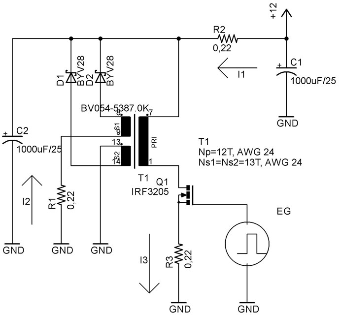
The Transformer I showed you in the first post:


There is two sets of Parallel Wires in there, on the Output, or Input depending on what the Transformer is doing. Each set of wires are wound and wired as if the wires are one, like this:


At all stages of the Cycle, the wires hold the same phase and polarity of Voltage and Current.


UNLESS:


Ferroresonance or nonlinear resonance is a type of resonance in electric circuits which occurs when a circuit containing a nonlinear inductance is fed from a source that has series capacitance, and the circuit is subjected to a disturbance such as opening of a switch.

Ref: Wikipedia


Ask the Question:

What's going to happen if there is any sort of 'Conduction' issue, like a disconnect, on one of the Coils? The Coils do still have a load connected, but at intermittent intervals. This depends on Polarity and Phase!

X is Switched off at a point in the cycle that the Diode D1 has already Conducted and Coil L2 has a Tension and thus a Current:

Note: Normally each outer leg of the circuit would be in the same Polarity and Phase, described above.

Q1, when on, conducts the same way as the Diode D1, from top to bottom, D2 is the internal Body Diode.


There will be large Transients, Voltage Spikes - Remember Voltage is E.M.F.

E.M.F is time Rate of Change of the Magnetic Field and its changing very fast!!! Between the two Output Coils, POC One and POC Two. This is the function of the Internal Diode: D2, this, I have tried to point out for a long time!

NOTE: Normally, in the above circuit both L2 and L3 would be held steady, never changing, so no Transients, no Over Voltages would be aloud to occur. However, this is a goal, we want to bring about this exact circumstance!


Remember, I showed you: May 15, 2015


So we have the ability to use this scenario:


The Voltage spike happens, we then have a Load period, and the Power: ( P ) is generated because: I = V / R

This is such an important post!

    Chris


P.S: Disgruntled Trolls are still trying... I am Logging IP's and setting a Honey Trap.

Jagau posted this 27 February 2019

Hi Chris

I think the transformer pictured above is a CVT or ferroresonant transformer.

The special feature of this transformer is that it produces a constant voltage (CVT) and so it has 7 wires,

two of which are used to place the xfo in ferroresonance.

Jagau

  • Liked by
  • Chris
  • ISLab
Chris posted this 27 February 2019

Hey Jagau,

The Transformer I pictured above is from a UPS ( Uninterruptable Power Supply ).

It is the basic idea that Akula used in some of his devices:


More importantly, the idea, the concept I am sharing is critical, it is the simplest way to achieve Above Unity Machines!

I showed above, this is the exact same technique Andrey Melnichenko used in his Lantern, later replicated by Akula:


@All:

If people want:


cheap,

easy to build Above Unity Machines,

with Energy to Spare


then they best learn what' s on this Thread!


Learn what happens when Q1 switches at the right time!


For years I have been showing the importance of Quarter Wave!


Learn how to OPEN the TAP!

   Chris

Atti posted this 28 February 2019

Learn what happens when Q1 switches at the right time!

I repeated several times. I did not fall into the belly of pleasure. It cannot be said that my fault is a lack of good results.

The effect is quite good, but the power taken from the power supply increases in parallel.

Anyone else?


Chris posted this 28 February 2019

Hey Atti,

  • Where were you switching?
  • For how long were you switching?
  • Did you monitor your Currents, did they flow in Reverse?
  • Did you get the Sawtooth Waveform?

I built a small circuit for this, only good for up to 2Khz, but its a start: Arduino Uni-Polar Parametric Switch - You will need to make necessary adjustments.

To answer the questions I asked you:

  • At or close to Peak Cycle.
  • For the rest of the Cycle, or with a pulse train of low duty cycle.
  • They did flow in Reverse: Bucking as Lenz's Law states.
  • Yes, I saw a Linear decrease in Voltage from my Voltage Spike which was twice the amplitude of my initial Voltage.


If you switch on the right side of the Cycle, the Magnetic side, then the Coils will do exactly as I have described. It must be the Magnetic side because: The Time Rate of Change of the Magnetic Field is how we create Voltage.


Remember Green is GO


The Cycle of Operation:

The Diode indicates half wave rectified AC Cycle:


In the following circuit:

We have the following operations:

  1. Diode D1 Conducts at 0.4 of a Volt.
  2. Mosfett is ON, from 0 Volt.
       Because of 1 and 2, Currents flow from top to bottom, down the outer legs of the Output Circuit.
  3. Peak Cycle, the Mosfett is switched off.
  4. A large Over Voltage occurs: The Waves Slap together, creating a Voltage Standing Wave, next is a Current Standing Wave.
  5. L3 swings, does a full reversal in Current Flow, D2 Conducts.
       Like the Mr Preva Experiment, we now have Currents Flowing Equal and Opposite.


Like dropping a Ball from a 10 storey building, instead of dropping it from your chair. Look for the Reaction!

What's an Over Voltage:

Should look very familiar to all here!


If it does not work this way, then there is something wrong! Keep trying, the full Current reversal only happens on L3. L2's Current does not change. Remember, this is the Natural State, this is how Nature wants two Parallel Wires to react, its Lenz's Law in Action!

   Chris


P.S: I encourage safety at all times! Electricity can be dangerous or even lethal! Experiment at your own risk. Please be careful this can be very dangerous.

cd_sharp posted this 28 February 2019

Amazing, man! Can this be done by powering L1 with DC square pulses instead of AC?

"It's just the knowledge of the coils and how they interact with each other" (Stephen Mark)

Chris posted this 28 February 2019

Hey CD,

Any and all experiments can be learned from. Essentially what we are looking at is a DC Pulse in a Sinusoidal shape.

   Chris

Chris posted this 01 March 2019

My Friends,

If I may get you all to print this thread, save it offline. Its the most important thread I have posted. The answers you seek are here, some work will be required. You must have a basic understanding of what I have posted in other Threads or none will make sense.

   Chris

Vidura posted this 01 March 2019

Hey cd, You could use a LC tank circuit on the primary and pulse with DC pulses, although frequency adjustment is more limited, change of capacitor value might be required. Vidura

Chris posted this 01 March 2019

My Friends,

Vidura is right, this can make efficiency higher.

In the beginning, after introducing my work for some months, I introduced some Circuits ( 2015-02-01 ):


You will notice the similarity:


Introducing my work, I used a Visual Cue, a Subconscious Trigger, an Indicator, and then, Partnered Output Coils was born!


Visually, we can grasp so many basic requirements!

  • One Input Coil.
  • Two Output Coils.
  • The Output Coils must Buck, Magnetically.
  • The turns between the Coils is an important factor.
  • The Two Output Coils must have close proximity.
  • Coupling Coefficient between the Coils is different.
  • The Output Coils have a mutual electrical Connection on each end.
  • The other unconnected ends of the Output Coils have more to them.
  • And more...


However, before I introduced Partnered Output Coils, the basic concept of using more than One Output Coil, together as a pair of Output Coils, was unheard of, then, others started catching onto the idea of using Two Coils as Output Coils.

We saw a few successes: Brad, ( June 19, 2015 ), who went to the darkside, Graham Gunderson, ( 08-03-2016 ), who almost exactly replicated my previously introduced ideas:


Graham did one of the best demonstrations I have seen, much better than I could have done!

Thanks Graham!

Also many others that do not wish to be known publically, which unfortunately does not help anyone, this defeats the purpose of a Public Forum and sharing publically.

Today, Partnered Output Coils is fairly well known in the Community. This is due to the slow, gradual, introduction of this Critical Technology. Many have little success, only because they do not monitor their Current as I have tried to show for quite some time. If your machine does not Buck at the right time, then all you have is a standard Transformer and possibly much less efficient than a normal one.

The secret is on this thread, you must make your Coils Buck at the right time!

   Chris
 

P.S: A lot of my posts have been tampered with, some forums I used to visit, have modified a portion of the posts I had made, so be careful in what you read and view.

cd_sharp posted this 02 March 2019

Hey, man

Let me see if I understand this correctly. You wrote:

  1. Diode D1 Conducts at 0.4 of a Volt.
  2. Mosfett is ON, from 0 Volt.
       Because of 1 and 2, Currents flow from top to bottom, down the outer legs of the Output Circuit.
  3. Peak Cycle, the Mosfett is switched off.
  4. A large Over Voltage occurs: The Waves Slap together, creating a Voltage Standing Wave, next is a Current Standing Wave.
  5. L3 swings, does a full reversal in Current Flow, D2 Conducts.
       Like the Mr Preva Experiment, we now have Currents Flowing Equal and Opposite.

You mean we should be monitoring the input current (through L1) and at "Peak cycle" ( peak input current ) we should switch off the MOSFET. When the new cycle starts (the input current starts growing) we should switch on the MOSFET. Is this what you have in mind?

Currently setting things up.. uC, current sensors..

Thanks

"It's just the knowledge of the coils and how they interact with each other" (Stephen Mark)

Vidura posted this 02 March 2019

The currents of L2 and L3 should be in phase at the beginning ( not bucking) and at the peak current the MOSFET have to be switched off this forcing a reversal of current flow in L3(bucking) , so best monitoring would be on L2 and L3. Regards Vidura.

Atti posted this 02 March 2019

Hey people.
There is still no good result.
I have tried two types of coils with two types of iron core.
- Has anyone else tried it?
- What is the result?
The drawings and theory are few here. Is there any practice besides?

Chris posted this 02 March 2019

My Friends,

@Atti - I recommend going back to The Mr Preva Experiment, learn as much as you can there, then come back to this.

@CD - Vidura is right! The direction of Conduction needs to be the same from Zero Degrees to around 93 Degrees.

Remember what I said above, referring to the Parallel Wires in the Transformer shown:

It can be experimentally proven that the Currents and Voltages will have a specific Polarity and Phase that is unchanging between the two Parallel Wires at all points during the Cycle.

It also can be proven that the Currents will be travelling in the same direction at all points during the Cycle. No matter what winding polarity is used - This is the result of the Driven Force Pumping the Current.


So How Do We Make Our Coils Buck?


While Coil L2, because of the Diode D1, has a continuous Conduction, for one Half Cycle, Coil L3 does not!


X is turned Off at around 93 Degrees, the Mosfet no longer Conducts in the direction it did!

We are Un-Shorting, yes I said Un-Shorting L3 across the Load!

Due to our very well versed Equal and Opposite Law, Diode D2, then Conducts! The Current in Coil L3 is FORCED to Flip Polarity! Bucking! Same as The Mr Preva Experiment!

Remember:


The Energy stored in the Near Field ( Green Magnetic Side) can be used to "Generate" Energy, exactly the same as an Electrical "Generator". There is absolutely no difference!

By interrupting the Conduction at around 93 Degrees on Coil L3, we are allowing the Coils to do something that all Electrical Engineers are taught to strictly avoid, the production of Over Voltages

Also known as Faradays Law of Electromagnetic Induction!

Remember, I have been showing for a long time:


The Parasitic Induction that Electrical Engineer's get rid of, are the things we want to use! Many years I have been saying this!


Fact Review

  1. We have Coils with a Voltage Potential on the Terminals!
  2. We have Coils that have Current Flowing through them!
  3. We have Maximum Magnetic Field in the Core!
  4. We have, at approximately 93 Degrees, a sudden drop of Conduction of Coil L3.
  5. We have, now, Current in one Coil L2, but no Current in Coil L3. But... it can not stay this way!


Two Coils in Magnetic Opposition, Pump Current, we already have the Voltage! Anyone with half a clue can see that this process produces an Over Voltage, all you need do is HOLD the bucking Currents until we need to Regauge again! Yes, Asymmetrical Regauging!

There is no difference to what I am showing you here and Andrey Melnichenko's Flashlight, or Graham Gundersons MIT or the above mentioned Video, shown here again:


Like I said, the unrealised "Gold Nugget". What's 5.65 times more?

Note: Parasites visit our pages, here to scavenge what's not theirs to scavenge, you are the only ones that can stop them! Take and use this, spread this to all your friends, and them, theirs's. Then it becomes worthless for the Parasites to visit!

Note: For this reason, a few details I have left out or been vague on, tried to explain in other ways, if you have followed, read and done the work, you will find them!

There is no rocket science here, I think all here can work the rest out!

Some of the smartest people I know can not workout the simplest things! Because they have not been taught to think for themselves! I encourage you to start thinking on these very simple facts, make for a better world, for us, for our kids and the generations to come well beyond.

Light Up The Darkness!

   Chris 

  • Liked by
  • cd_sharp
  • ISLab
Atti posted this 03 March 2019

Hey Chris.

Do you think I'm a parasite? 

Chris posted this 03 March 2019

Atti - Absolutely not!

Let me define a parasite:

A human being that, prays on others, lies, cheats and steals;

A human being coming to read all our hard work, learn from it, take it, claim it as their own, and Patent it, and or, then going on to make money from our hard work, and or, then come back and stop us and others from working on our own work.

A human being that never gives credit to others, when credit is due!


This forum is ours! Our work! We are a collective! The work I have given, I have placed into the Public Domain! Not to be Copyrighted, not to be Patented, not to be owned, never to be sold!

I value all genuine members!  cool

More than you know!  wink

I do also know how some, a small minority, work. I have been subjected to some pretty low deeds in my time, finding it hard to trust anyone! Always a little suspicious, always a little wary. These people, that pray on others, lie cheat and steal, they are Parasites! The ones we work hard to combat!

Hold your head high Atti, for there is a reason I suggested to go back to The Mr Preva Experiment! Incorporating some Diodes in combination with another Capacitor may give you some very important insight!

Look at what Plate is being Charged by what Current!


It is the little things taken for granted that hold the most value!

Ref: My above Post


Don't give up, study closely... Look for and coax the effects I have shared! This thread make's it easy!

   Chris
Jagau posted this 03 March 2019

Hi Atti

stay in the wave

you are a researcher as important as everyone else.

laughing
Jagau

  • Liked by
  • Vidura
  • Chris
We're Light Years Ahead!
Members Online:

No one online at the moment


What is a Scalar:

In physics, scalars are physical quantities that are unaffected by changes to a vector space basis. Scalars are often accompanied by units of measurement, as in "10 cm". Examples of scalar quantities are mass, distance, charge, volume, time, speed, and the magnitude of physical vectors in general.

You need to forget the Non-Sense that some spout with out knowing the actual Definition of the word Scalar! Some people talk absolute Bull Sh*t!

The pressure P in the formula P = pgh, pgh is a scalar that tells you the amount of this squashing force per unit area in a fluid.

A Scalar, having both direction and magnitude, can be anything! The Magnetic Field, a Charge moving, yet some Numb Nuts think it means Magic Science!

Message from God:

Hello my children. This is Yahweh, the one true Lord. You have found creation's secret. Now share it peacefully with the world.

Ref: Message from God written inside the Human Genome

God be in my head, and in my thinking.

God be in my eyes, and in my looking.

God be in my mouth, and in my speaking.

Oh, God be in my heart, and in my understanding.

Your Support:

More than anything else, your contributions to this forum are most important! We are trying to actively get all visitors involved, but we do only have a few main contributors, which are very much appreciated! If you would like to see more pages with more detailed experiments and answers, perhaps a contribution of another type maybe possible:

PayPal De-Platformed me!

They REFUSE to tell me why!

We now use Wise!

Donate
Use E-Mail: Chris at aboveunity.com

The content I am sharing is not only unique, but is changing the world as we know it! Please Support Us!

Thank You So Much!

Weeks High Earners:
The great Nikola Tesla:

Ere many generations pass, our machinery will be driven by a power obtainable at any point of the universe. This idea is not novel. Men have been led to it long ago by instinct or reason. It has been expressed in many ways, and in many places, in the history of old and new. We find it in the delightful myth of Antheus, who drives power from the earth; we find it among the subtle speculations of one of your splendid mathematicians, and in many hints and statements of thinkers of the present time. Throughout space there is energy. Is this energy static or kinetic? If static, our hopes are in vain; if kinetic - and this we know it is for certain - then it is a mere question of time when men will succeed in attaching their machinery to the very wheelwork of nature.

Experiments With Alternate Currents Of High Potential And High Frequency (February 1892).

Close