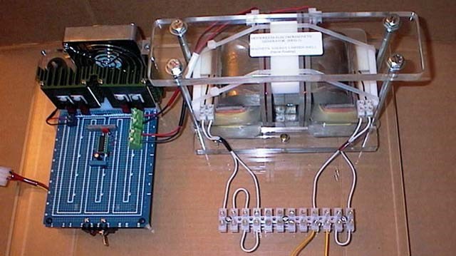
Chris's Non-Inductive Coil Experiment

  • Topic Is Sticky
  • 29K Views
  • Last Post 04 July 2023
Chris posted this 08 October 2019

My Friends,

I am going to show a small experiment, one that follows the works of Andrey Melnichenko and even Tariel Kapanadze's works and as we know many others.
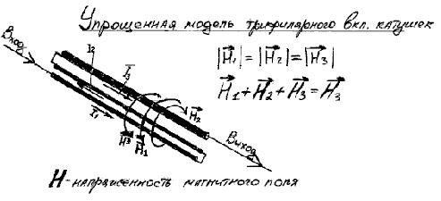


We have discussed here before, the fact that H3 is H3 simply because H1 and H2 cancel out: H1 + H2 + H3 = H3, why is this so, because H1 is Positive and H2 is Negative! We have seen this equation before: 1 + -1 + 1 = 1.

I think with Fighter's success recently, its time for some hands on!

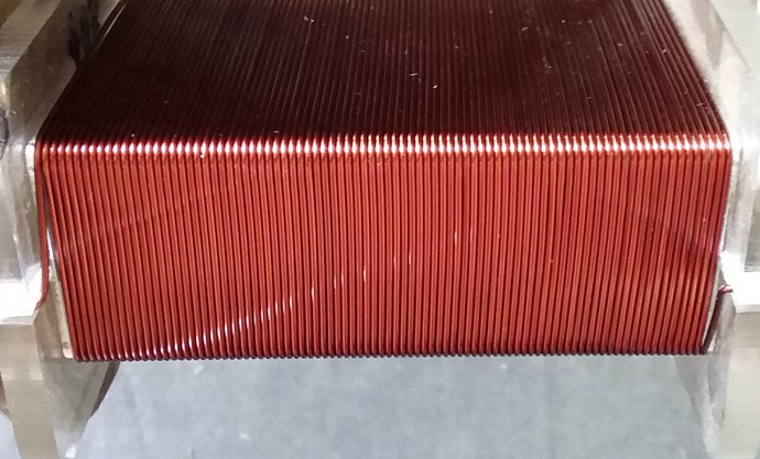
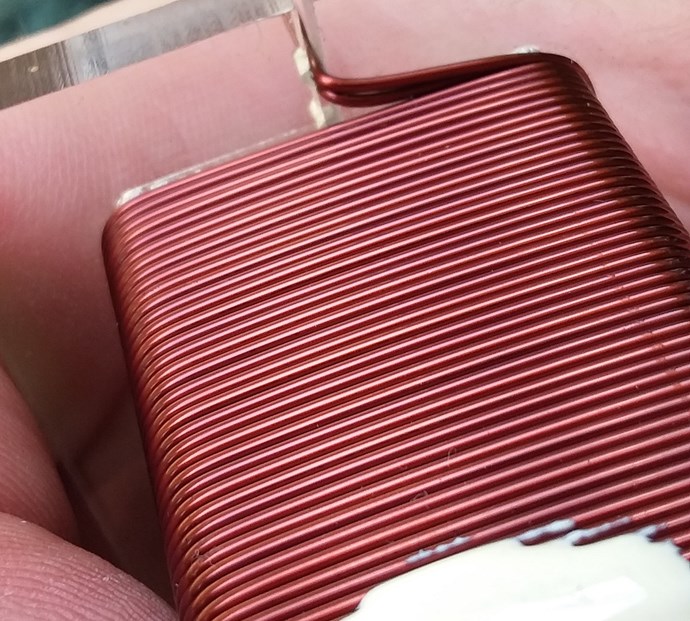
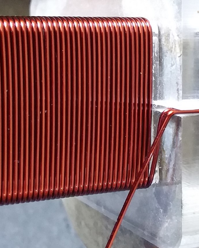
  • First Layer: 88 Turns.
  • Second Layer: 43 Turns.


Layer One:


Layer Two:
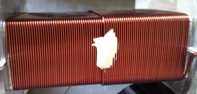
 

Turns Direction:
 

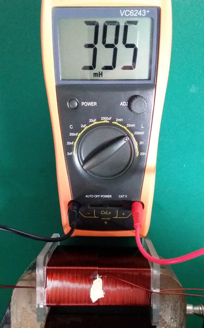
Layer One Inductance:
 

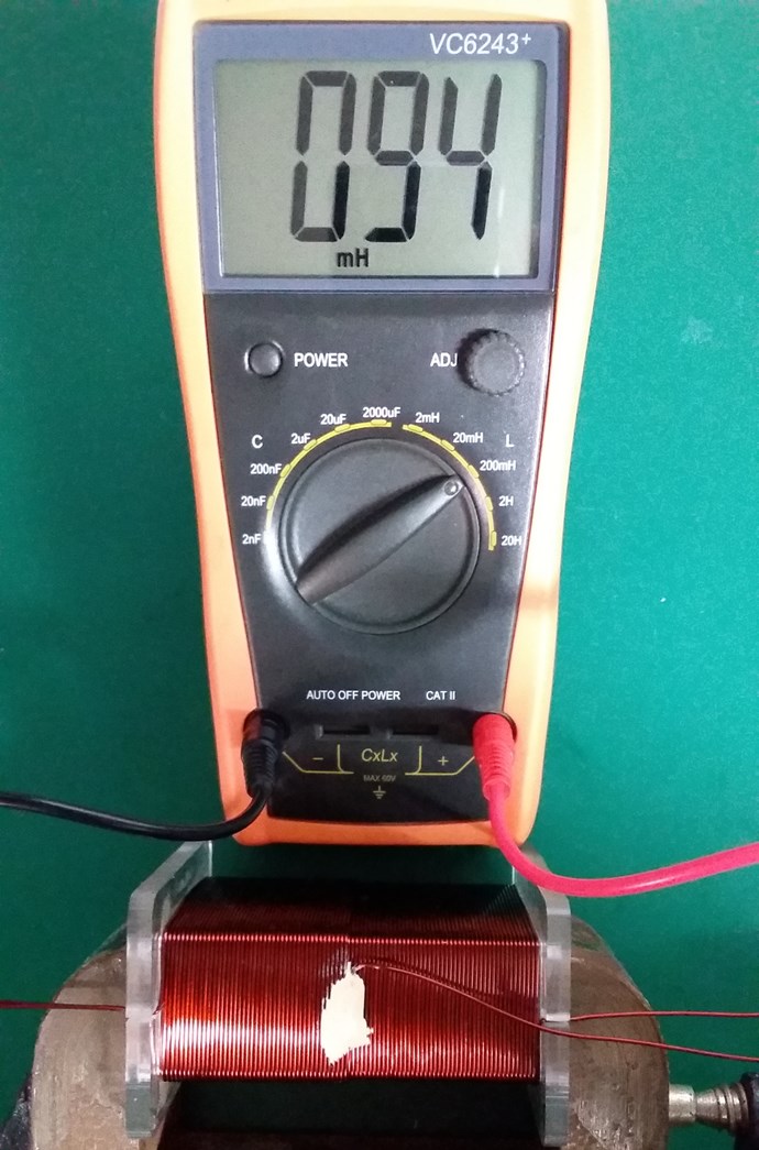
Layer Two Inductance:
 

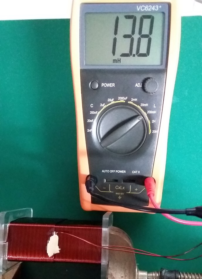
Non-Inductive Connected:
 

Layer One Resistance:
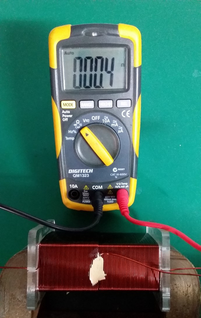
 

Layer Two Resistance:
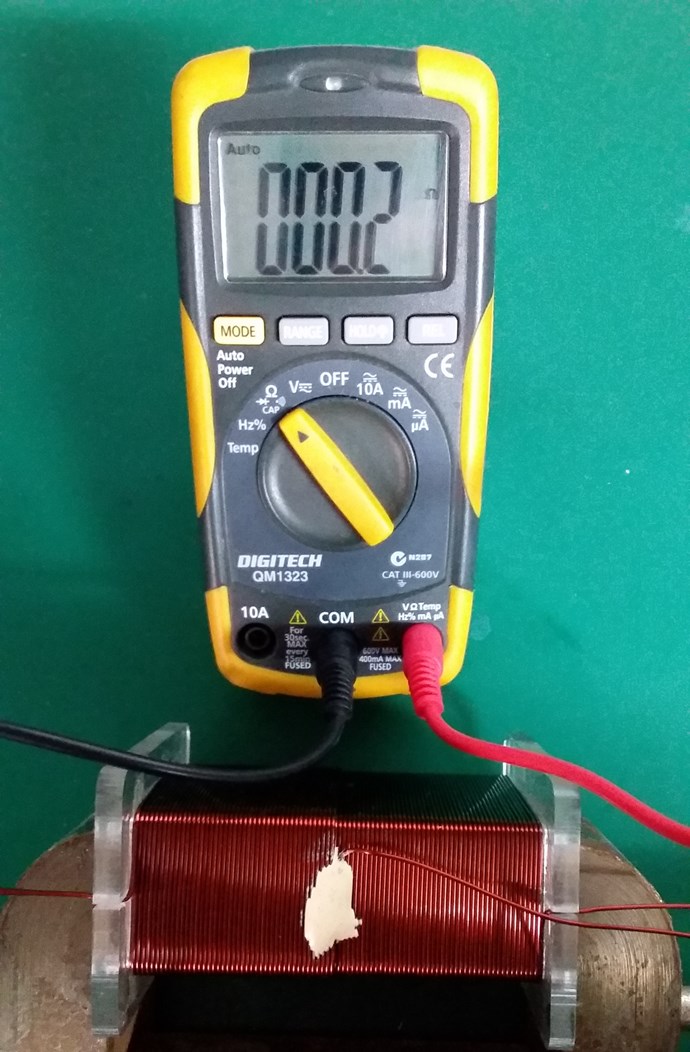
 

Closed Loop Resistance:
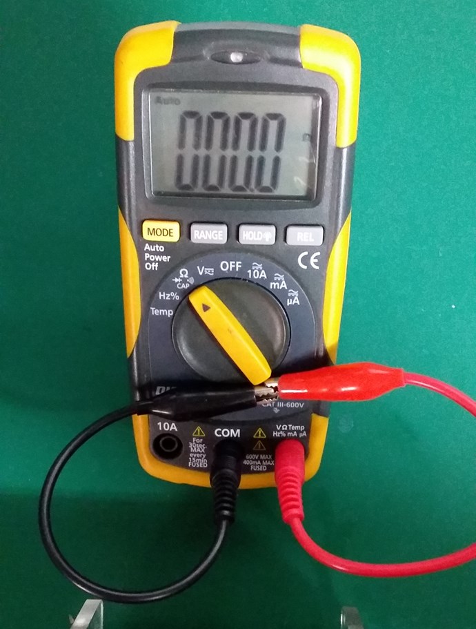
 

My Coil, like Andrey Melnichenko's, is 0.33 + -0.33 + 0.33 = 0.33.

Two thirds of my Coil is canceled out. My Circuit looking like this:
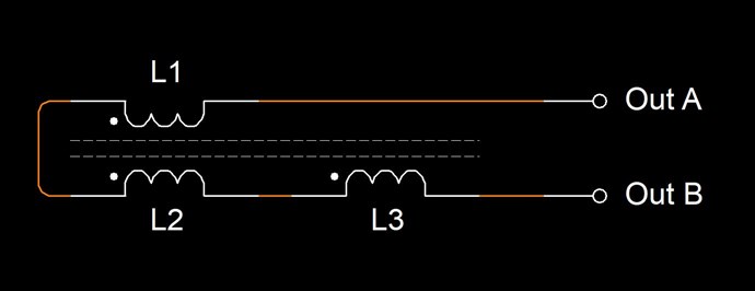
Where:

  • L1 and L2 are Non Inductive.
  • L3 is Inductive.


If this Coil is carrying 1 Ampere of Current, and exactly one half of the Coil is Non-Inductive, then Turn for Turn, only 45 Turns will create an M.M.F, which is considered as 45 Turns x 1 Ampere = 45 Ampere Turns or 45At.

Science tells us, that Turn for Turn, where we have Non-Inductive part of the Coil, this part of the Coil does nothing! Creates no Magnetic Field, therefore does nothing.

However, from Experiment, we know that this part of the Coil DOES do something! Remember Floyd Sweets paper: Nothing is Something, this is the same!

At Resonance, we have a perfect Standing Wave! We know this as Magnetic Resonance! Where each Magnetic Field is 180 Degrees out of phase:
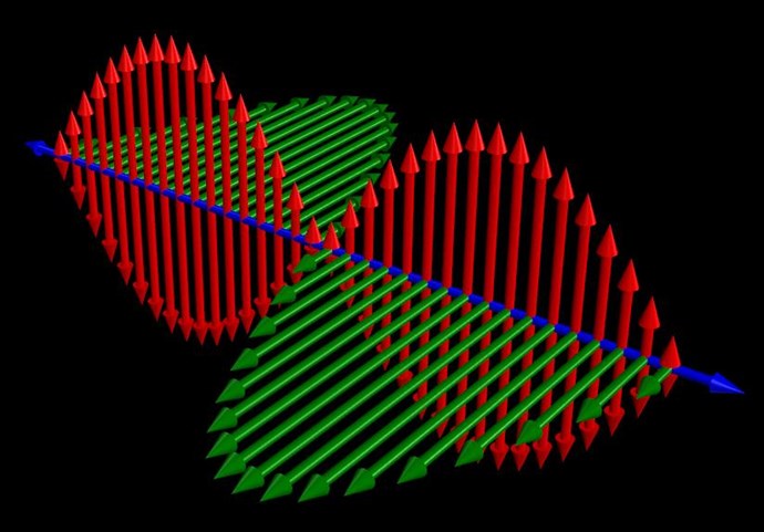
 

Now, straight away, we should see a problem! Why? Kirchhoff's Current Law says the Current must be equal at every node, but we have Turn for Turn, one Coil that is Inductively Zero, and another Coil that has only a part of the Induction canceled!

In the specific case of positive charges moving to the right and negative charges to the left, the effect of both actions is positive charge moving to the right. Current to the right is:

I = da+ / dt + da- / dt

Negative electrons flowing to the left contribute to the current flowing to the right.


Each node does not equal the other, so the Circuit must balance out, Current is Increased as the Standing wave shows us.

Remember what Induction is? See here: Non-Linear Inductance

Induction gives us an approximation on the Coils ability to carry a Current: L = ε / di / dt

By Bringing a Coil arrangement like this into Resonance is our task.

Where each Electromagnetic Wave travels in opposite directions. One through the other in the same space.

THE NATURE OF SPACE

Space itself is the ability to accommodate energy. Consider for a moment the following illustration:

A signal (energy) is transmitted from point A to point B. A and B are separated by a finite distance. Consider three periods of time:

  • The signal is launched from A.
  • 2) The signal resides in the space between A and B.
  • 3) The signal arrives at B.

If (3) occurs simultaneously with (1) we say that the signal has traveled at infinite velocity. The signal has never resided in the intervening space and therefore there exists no space between A and B. A is virtually at the same point in space as B. For real space to exist between A and B it is necessary that a signal travelling between them be "lost" with reference to both points for a finite period of time.

Now we know that for real space to exist between two points a signal travelling between them will propagate at a finite velocity c, ( c = 1 / √με )

If a signal will not travel between two points, as in the case when c = 0, then we can also conclude that there is no link or intervening space between them. 

Ref: Floyd Sweet - Nothing is Something.


Floyd Sweet tried very hard to make c = 0! What does this mean? It is simply a Standing Wave, a Team Wave was used:

It is a simple matter using the equations E / H = √με and c = 1 / √με for a team wave to get rid of H and c and so convert the first equation into the well known equation for energy density in the so-called electrostatic field.

Ref: Floyd Sweet - Nothing is Something.


I have pointed out: Why 'C' is equal to One in these Devices.

We have a lot of data!

   Chris

Order By: Standard | Newest | Votes
Chris posted this 22 April 2020

My Friends,

Yes, I agree, Compliments all round! You all are doing awesome! Keep your Chin Up! Right now, you have effects on the Bench, that are not properly explained in Science!

Right now, we are working in Un-Charted Scientific Territory!

This means we are working Blind!

I urge, working with each other, being able to share, bounce ideas off each other, and work toward a greater understanding!

This is the most important part: Understanding!

Be proud My Friends! We have started a Revolution! We are working on the Edge of Tomorrow for Tomorrow, no one else on the Planet is doing what we are doing!

Best wishes,

   Chris

Ourbobby posted this 26 April 2020

Hi All,

          If I may be so bold! I have rewound my coils to represent the coils of Atti. Although I have a larger core size, which gives its own problems with replication. I have AMCC200, on which I have wound #18 160 turns and 40 turns of 7/10mm wire. I get resonance at 30.2Khz with 25% pulse width through frequency Generator. 

To get a response to this above arrangement I am guided by Don Smith's comment of energy increase by doubling the voltage, the calculation therefore relies upon the resistance being doubled too, being based upon Ohms law.  Therefore, I am inputting  almost 15watts to P1 to get an output across a resistive load on S1 coil, 24v @ 60mA. This ordinarily might look like a simple transformer transfomation except for the high voltage generated within the coils! So I am thinking that I am using the sledge hammer approach to get an effect!.

I have also used the SG3525, due to its higher voltage opportunities. However, I am unable to effect the deadtime calculation with a resistance between pins 7 and 5, as is specified in the datasheet, and by numerous online comments regarding methodology. So I am at a loss as to what I am doing wrong! And, I think that if I were to be able to activate the deadtime, then I might have an opportunity to get closer to the resonance of the device. Which at the moment is operating with 50% pulses in totem pole connection.

The other consequence, that has come to mind is that, because it takes 24v and minimum 60mA to activate the cores - magnetically. Don's method might not be appropriate. You hear them clamp together and a glow in the light glow is evident. Therefore, It is possible that  by reducing the wire guage for the larger core I shall have to rewind lower guage, which will allow lower power input? 

Anyway, these thoughts are my way of updating my progress. The tunnel still seems long, only a pin hole of light!.

Regards


ourbobby

Chris posted this 26 April 2020

Hey Ourbobby,

If I may, don't re-wind the coils, keep them the same, don't change them.

Do a series of Experiments, documenting each experiment. Specifically focus on "What the Partnered Output Coils are doing" - This is the "Generation" Phase.

I have listed here and in many places lists of things to do to improve on the Effects:

  • Check your Core for a Gap, if there is a gap, decrease it, if there is no gap, try to increase it.
  • Check your Input Circuit, start documenting your Circuits, per video and what you try and when.
  • Change the Primary, POCOne Coil, the Loaded Coil, to the Opposite Coil.
  • Adjust the Coupling from one Coil to the Other. Measure the Assist the Coil gives while Adjusting...
  • Measure your POCOne Current and see if POCTwo Voltage aligns up as I showed in my videos. Remember, its the Change in Current that creates the Voltage.
  • Really, look for the adjustments that the machine likes to see, if the effects drop off, you are going the wrong way, go back.
  • Measure the slope of your Input Current, vs Voltage gained on POCOne and same again on POCTwo.
  • Does your Input go Down, or go Up when Connecting POCTwo?
  • Try pulsing, with the same config, but a second switch and a small battery or something on POCTwo to see whats supposed to go on when POCTwo Assists the Machine. This will help you to get a feel for the operation.
  • Check your input does not have some sort of protection diodes somewhere, stopping the input Current coming back.
  • Measure best Standard Transformer COP, set yourself a standard Baseline to work to, and compare to COP with POC. See what Configuration assists and drops your Input.
  • Remember, the Magnetic Field by itself is Symmetrical, so perhaps best stick to the Configuration I showed in my Video. Why? The Magnetic Field has two poles, each pole has a Propagation delay, lets try to balance this delay for the mean time.

Ref: Chris, Me, posted here.


Document what your Coils like better, look for the Path Forward. Of course, this experience, the experience gained here is critical in understanding what is required to make this work the best way, and why these simple things can make a difference.

Check everything, turning up your input a little more each experiment, to see what your machines like! Look for the Effects, the Numbers will follow!

Ourbobby and others reading, note the output difference with the Fan and without:


_______________________________________________________
With out Fan:
_______________________________________________________

in v: 12.80
in amp: 0.722
= 9.2416


out v: 10.40
out amp: 1.639
= 17.0456

COP: 17.0456 / 9.2416 = COP = 1.84

_______________________________________________________
Loaded with Fan:
_______________________________________________________

in v: 12.80
in amp: 1.356
= 17.3568


out v: 10.40
out amp: 1.633
= 16.9832

COP: 16.9832 / 17.3568 = COP = 0.98


Excellent work and Thank You for Sharing!

Best wishes,

   Chris

Atti posted this 26 April 2020

Ourbobby

Really take a few more measurements. Don't take it right away.
Some thoughts.
-Only use coil L3 to find the point where your current consumption from the power supply is highest. Frequency-supply voltage with default but the fill factor should remain small. Max 30%. (I don't think dead time matters because it would only matter if both outputs of SG were used.)
-Now put the load on the L2 coil. The current drawn from the power supply should increase only slightly. But because the resistance of the light bulb changes, the current consumption remains low. Video 1:50 (That's why the incandescent method also cheats a lot!)
-Notice that the ammeter suddenly deviates but falls back.
In my opinion, this is the best working point.
-See what parameters you use in this case.

  At least the kind of transformers I've tried so far.
But unfortunately there is little experience.

Atti.

Chris posted this 26 April 2020

My Friends,

When you get to Magnetic Resonance, at the right point, you will know, take the above example.

Its a bit like taking a Mini vs a V8 for a test drive.

Look for the effects My Friends, then you will see the difference, be patient!

Best wishes,

   Chris

Ourbobby posted this 29 April 2020

Hi All,
Thanks for the information. I must be seriously missing the point here. I follow the procedures and the results I get have nothing in common to those demonstrations that show the results we should be looking for. The time I have available at the moment is a smallish window. With my current set up, very simple, I am only getting 30mA or so!. This is the coil arrangement with P = 43 turns, S1 and S2 having 280 turns. I reduce to P = 22 turns and my current improves to 80 mA. No matter which way I connect the loads across the coils for measuring, am I able to approximate to reading the current flow required for the first leg of the sawtooth. It makes no sense to me. Even if I use a variable resistance, I am unable to see the current flow.

Realistically, how many times does one have to manipulate a experiment, to get to the basic point of reference, based upon the information of working models shown and refered to, before they give up?

I have modelled an experiment based upon Atti's circuit, as close to his as I can get, and I get nowhere near what I am supposed to. What am I missing? Well, for a start, replications and or similar, should have a more clearly defined outline. For example. I get the what I am looking for with the period of time constant for charging the primary which transfers this to the S1. This is where we should find the current growth we are looking for. So we use a TVS diode. Without having an arsenal of these values, what range should I be looking to calculate? The transformer turns ration of the P anD S1 as a destination point? I leave it there.

Regards

ourbobby

Chris posted this 29 April 2020

Hey Ourbobby,

Perhaps have a break for a while come back to it fresh after a break?

CD's work is very inspiring if you wan to watch his videos?

The point is to learn what your machine likes and does not like. This is comparable to the evolution of any Technology. If you look at Elon Musk's Progress, Many failures, but look how many successes he has had also! Just broke the record for Launches into space, beat the Atlas 5 missions. 84 compared to 83 of Atlas's.

Learning a little more on each experiment is the goal. Don't change the Coils every time, that is not beneficial in the early stages.

We are here if you need some help, if you want some advice, direction, basically small steps for little feet, Floyd Sweet went from 19 Watts to 5000 over the course of 5 years.

No doubt he had 20+ years experience before that!

Please try not to put too much pressure on yourself, it is hard when you expect every experiment to be successful, it cant be this way, we all go through failures and have the odd success...

Best wishes,

   Chris


P.S: Take some time, think about each Coil, what the stages are, like an Engine has Firing Order, think about the Firing Order of Partnered Output Coils. Think about what Each Coil see's at the point of Firing. Think about the Action and Reaction of that Coil.

I am sure, @CD, you would agree this is important to understand isn't it?


Atti posted this 29 April 2020

Hey Ourbobby.

I’m not a transformer expert, so I’m just saying my opinion. You don't have to agree with what I'm writing now.
  I think whatever transformer you take out, each one should show some effect. Now efficiency doesn’t matter, profits don’t matter. Only the existence of effects. You don't even need a diode. Only two loads. A smaller and a larger light bulb.
In this video, I use an average hypersil transformer.
(I wanted to buy a larger AMCC core but I gave it up. I don't think only such super material can be used.)
The behavior (effect) of currents and voltages is clearly visible. Some thoughts in the description.Maybe a CD can help more.

Chris posted this 29 April 2020

Hey Ourbobby, Atti, CD and all Readers,

Its true, CD is very Wise! Famous Aircraft Designer, Burt Rutan said:

Testing leads to failure, and failure leads to understanding.


Its so true, direction, understanding and ability come from failure! However, one must define what a Failure is! In my opinion, you have not failed! You have succeeded! You have achieved the required Waveform! The problem is only the Measurements! 

My Advice: In the early stages, do not focus on the Measurements! Focus on the Effects!

My Dear Friends, one of the reasons I say: "Look for the Effects" is simply because as you learn about these effects, you learn more of an area that is largely unexplored in Science, at least Conventional Science! As you learn more about these effects and how to improve on them, the Natural thing is to turn your input up slowly! This allows you to observe better, and be careful at the same time whats occurring. I have also said: "Monitor your Currents", this is a Magnetic Field Effect Machine! You need to increase your Magnetic Fields so you can see better whats going on.

You all are awesome! You all are part of this Historical Drive to push Humanity Forward! You ALL Should be SO PROUD!

Best wishes, stay safe and well!

   Chris

Zanzal posted this 29 April 2020

Realistically, how many times does one have to manipulate a experiment, to get to the basic point of reference, based upon the information of working models shown and refered to, before they give up?

Hello Ourbobby,

We've all been there I think. At the point or past the point of giving up. Only to come back later and try again. If I may recommend a new metric for success : Learn something new about electrodynamics = success. Learn nothing new = failure. Focus on what you can learn. When you are doing your experiment and you take your measurement focus on facts not emotion. Don't anticipate success, examine your results and look for opportunities to improve them. When we talk about famous inventors like Bearden and Sweet, keep in mind those folks had Ph.Ds and an understanding that showed they earned them. Bearden acknowledged it took him years to figure out the solution. Tesla was also hard at work for many years. None of those guys were born knowing anything. They had to learn. Likewise we must learn too.

And remember you are not alone here, we're all working and sharing to help each other learn. Ask questions, try new things, challenge your own assumptions.

Ourbobby posted this 01 May 2020

Hi All,
Thanks for the support!

Here are a couple of photos of my progress. I have found that too much current will impede the current through the coils. Better solution is higher voltage and lower current. So, I need to build a more useful power supply, specifically for this project.

I can now see the current I have been looking for and with a poorish transfer after chop-off. One photo is shot of current rise, the other is the "slapping"? which rattles away while I am trying to stabilise the frequency around a certain point to maximise my current. To my mind I think I am closer to what might be the resonating effect? I am also mindful of the purpose of Don's GDT effective for high voltage.

regards

ourbobby

Chris posted this 01 May 2020

Hey Ourbobby,

Good to see you back my Friend!

If you don't mind me saying, be careful with your scope, Spikes like that may do damage to your scope, High Voltage is bad for scopes.

Good work and Thanks for sharing!

We are working on a method to give others more information to get a machine working. It may be worth your time to follow my latest threads. It gives information on why its sometimes a bit hard to get machines working. We think, not sure yet, but we think that there is a point near Saturation, where the Machine needs to Operate.

I am sorry, I can not be certain and can not prove this for sure. I am working on it to see if I can give others more information on this.

Best wishes,

   Chris

  • Liked by
  • Vidura
  • mich
Ourbobby posted this 01 May 2020

Hi Chris,

              Thanks for the caution. I was just adjusting the frequency after lowering the current, when I saw the current trace on the scope. Then without warning, the "slapping" or what i think is slapping, appeared in irregular bursts. I have the diodes P6KE27A, connected across the S1and S2 for measurement purposes. They are what I have! 

Yes, a common project for all and sundry to share might be a useful concept. Think how useful Don Smith's devices would enhance the lives of those stuck in refugee camps?

I am grateful for your comments and encouragement. The difficulty is not being able to see what we are trying to accomplish at times.

regards

ourbobby


  • Liked by
  • Fighter
  • Chris
Chris posted this 01 May 2020
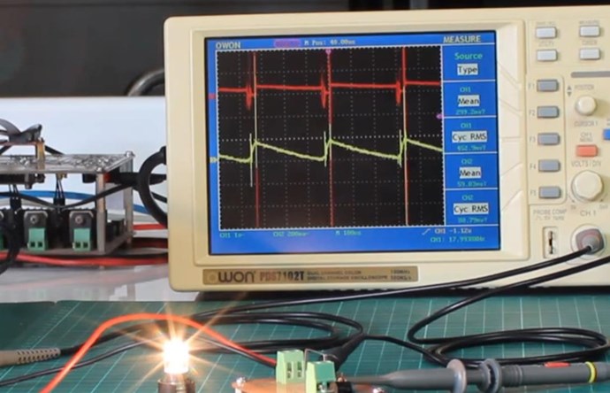
Hey Ourbobby,

The Focus should always be on Energy "Generation". Focusing on what your Coils can do when they interact together!

If I may, start reading some of the other threads also, here is an example:

My Friends,

@Gravitation, YoElMiCrO has given you the worlds biggest gift!

We see:

  • Method of "Generation", Charge Separation.
  • Charge Pumping, Opposite Magnetic Fields.
  • And more...


YoElMiCrO is right, this is very important!

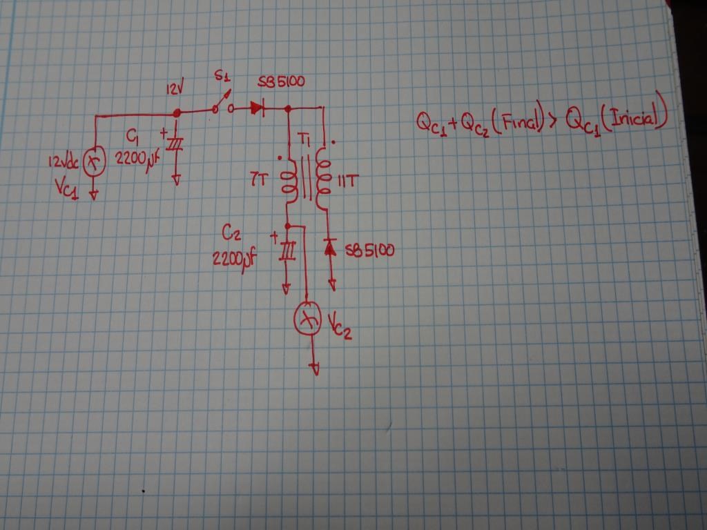
However if we use the above circuit we will see that the sum of the charges will exceed the initial load and as efficiency is (EndQ1+EndQ2)/StartQ1 AU is posible..

This says a lot, everyone start analyzing ...
Q = VcC = It.


The Charge on a Capacitor is: Q = CÙ V

Where C is the Capacitance in Farads and V is Volts. Q is in Coulombs if Memory serves. So this means, 2200uF = â€­0.0022‬ Farads. Voltage on the Capacitor is 12 Volts at the start. The switch S1, when closed has an RLC Time Constant across the Tank Circuit. For series RLC circuit Time Constant is 2L/R and for parallel RLC circuit Time Constant is 2RC. This means after 1 t, the Charge on C2 can be more than C1!

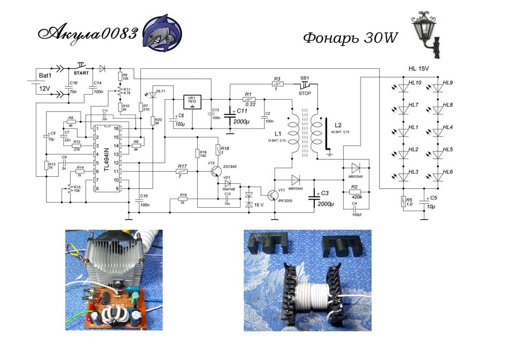
Note the Similarity to Akula's Circuit! Everyone! This is important! We all have to work on this together! We must Share this with the World! We must make change for our Children and their Children!

Best wishes,

   Chris Sykes


As soon as C2 shows more Charge after 1 Cycle, then you know your Coils are interacting together in the right way!

My finished equation:

My Friends,

I should have finished the Equation off!

The Charge on a Capacitor is: Q = CÙ V

Where:

  • C is the Capacitance in Farads.
  • V is the Voltage in Volts.
  • Q is in Coulombs. 1 Joule (J) = 1 Volt X 1 Coulomb.


So this means, 2200uF = â€­0.0022‬ Farads. Voltage on the Capacitor is 12 Volts at the start.

As YoElMiCrO said: 

StartQ1 = 0.0022‬ Farads x 12 Volts = â€­0.0264‬ Coulombs.


using the same process, if C1 and C2 ( EndQ1 + EndQ2 ), after 1 Cycle has: â€­0.0265‬ Coulombs, then we have an Above Unity Machine. More Energy Output than was Input!

NOTE: This is possible because we have an Open System, a System that has an Extra, Asymmetrical Energy Input to the System!

Best wishes,

   Chris Sykes


This is an excellent example of the Interactions required.

Best wishes,

   Chris

Ourbobby posted this 06 May 2020

Hi,

      Having seen the summary of Northern and southern hemispheres in the tutorial videos, where there is no activity about the equator, I am curious if the opposing magnetic fields of the two hemispheres might interfere with the use of CW and CCW wound coils. Given that most of the activity surrounding this forum topic originates in the Northern hemisphere, Would the souls of the southern hemisphere have to wind in reverse to get a similar effect?

Just a thought

ourbobby


  • Liked by
  • Chris
Chris posted this 06 May 2020

Hey Ourbobby,

Its worth doing more research here, gain an understanding that Science does not tell you!

The combination of various effects is important to visualise and be able to think about! Out Thread: The Field Structure of Nature gives a big head start on this topic!

Best wishes,

   Chris

  • Liked by
  • chocolate blanco
Ourbobby posted this 06 May 2020

@Atti, 

Hi, 

      Are those bridge rectifiers on the coupling boards?

Thanks

ourbobby   

  • Liked by
  • Chris
Atti posted this 07 May 2020

Ourbobby

Which layout do you mean? Draw it.

Ourbobby posted this 07 May 2020

Well, here is a mystery! I have got my replication of Atti's set up working. Albeit, with a very high current flowing through a 12 volt globe, which suggests 60 watts. I do not get a 240v globe to show the 60 watts, only a dull glimmer of light. However, that is not the mystery.  Today, when I return to my bench, the set up starts with a crackling sound, and i gradually adjust the frequency to get the brightest point of the 12v globe. And, I get the high pitched audio sound coming from the set up. All good. I turn it off the put some probes into the set up and it has all disappeared! Nothing! I am not getting any output. I have pulses going into the same set up. Is this what Floyd Sweet experienced?

ourbobby

YoElMiCrO posted this 07 May 2020

Hello everyone.

@ Ourbobby.

I think there is nothing mysterious about your sep tup.
It seems to me that you only entered the non-linear operating point of the core,
where the initial instantaneous current is high, I go into ferro-resonance.
It is because of that current that the cores vibrates, so to speak, and I leave
to do it when reconnecting because you are right at the break point in high frequency.
If this is what I am saying, when it stops vibrating you lower the frequency until it occurs, then
you upload it again.
I hope it will help you.

YoElMiCrO.

Chris posted this 07 May 2020

Hey Ourbobby,

YoElMiCrO is right!

This video may help some:


The Noise, the Knocking, the Vibration, its an indicator. I also show here, a similar thing:


Remember Floyd Sweets Sponge:


When the Core starts getting noisy, you have a very large Magnetic Field Opposition, you know your'e getting close! Coil Polarity can play a role!

Best wishes,

   Chris

Chris posted this 08 May 2020

My Friends,

At the Input, we have to remember, there is an Energy cost! 

When I did my MEG Replication, I read a passage that did not make a lot of sense:

The experimentally-measured data was extrapolated to describe operation at an input voltage of 100 volts, with the input current being 140 ma, the input power being 14 watts

Ref: The Meg Patent.


Seeing the big Heat Sinks and Fans on the Fets, I was surprised! See here:


What I am saying is, don't be scared to spend a little on the Input! Stay in your Switching Units Parameters! But don't be scared to use a little Input Power! Its important to get the Machine working!

You must remember, as your Machine moves into Resonance, your Input will drop off as a Function of the Magnetic Fields in the Machine! The Higher the Magnetic Fields, the more is sent back to your Input, meaning the LESS Input Power You Use!

Remember:

The VTA "likes" to always see a minimum load of 25 watts.

Ref: FLOYD SWEET'S VTA UNIT - by Walt Rosenthal


This is really important to see! Part of the Experiment! You need to get the Magnetic Fields working properly Together!


Best wishes, stay safe and well,

   Chris

Attached Files

Ourbobby posted this 12 May 2020

@Atti,

  Hi, regarding the 120v 25ma globe used in your test set-up, is this a neon globe or an ordinary light globe? I am only able to get this switch working if I use a neon globe. If I use a light globe, all I get is a continuous voltage, no switching.


EDIT: Got it! I have looking at it in reverse!!

Thanks

ourbobby

Ourbobby posted this 13 May 2020

@Atti,

          What do you think i could use as a substitute for the 120v 25ma globe? It is impossible for me to find one here, Importing one from USA is likely to force me to buy a minimum 100 or so! I am using neon globes at the moment and have had to resort to 70v neon. 100+ volt neons are doing too much damage as they pulsing too high a current. Knocks out the mosfet and also the 3525! The 70v neon restricts the circuit voltage! 


regards

ourbobby


  • Liked by
  • Chris
Atti posted this 13 May 2020

Ourbobby.

As far as I know, neither Chris nor CD uses the protective circle tied to the Fet source leg. Look at their switch circuits, or maybe ask them. But maybe it would be better to buy one from them.
Or Vidura switch circuit.
But to the specific question instead of the light bulb:
-Maybe it would be better to use a switch with a higher voltage tolerance.
-Perhaps a snubber (100ohm-10n). I made the protection circuit because the fet is low voltage (IRF 540) and of course the self-inductive voltage is visible at low power consumption.

Ourbobby posted this 13 May 2020

Hi Atti,

           Thanks for the reply. When I increased the voltage tolerance, that is where the damage would occur. The sharp discharge.I am able to run at with some sort of oscillation at around 70 volts across the protective circuit. My input is 24v. However, although I can appear to be oscillating I am not getting any output across S1 or S2. I take that to mean that I am getting limited current through put. For some reason, I am unable to increase the current through the primary, which I am thinking is the source of my issue with serious success!

Thanks again for your assistance.

ourbobby


Ourbobby posted this 15 May 2020

Hi,

Well I think I am getting closer! Cannot seem to get any current though. I have small wattage globe across the coils, will not light up. So likely too that I am not bucking properly? Two photos, one with probable output for envelope conversion and the other current layout. Coils joined as per guidelines to bucking coils.

regards

ourbobby


mich posted this 15 May 2020

Hi Chris considering your last post, this for let you know that i'm working :-)  I would like also to thank you for your effort so far and the others too.


In my replication at the moment nothing special resonance to see, the imput is 11V 400mA, by varying the dutycycle I don't see great piks of power on the load but a linear action, for now I build a normal trasformer with a feature that the load is supplied only by flux discharge in the core.

I try many length of coils in many configurations, I try to maximize the L3 work (the support coil without load) which for now it doesn't contribute much to the output, next I will try different cores.. or change schema..

photos of last configuration:

bye!

Vidura posted this 15 May 2020

Hi Ourbobby According to the scope shot you have an output of 170vpp , and maybe no current? Check the impedance of your load, it might Bry too high. Regards Vidura.

Ourbobby posted this 15 May 2020

Hi vidura, 

Thanks for the input. There is much learning to absorb just on magnetic technique. I am switching the primary through the discharging neon. Good for keeping the batteries charged, but, not so good for current into the system. I am showing about 400uA total being used through the primary Does not seem correct to me. But will account for the issue of power loss. I have also swapped the L1 and L2 terminals and the output is now 340 vpp. Waveform has changed to fractured sine wave. Will post a photo tomorrow. Has a funny little dip at the peak which I think might be the winding differences of the two L coils. One has 10 turns more than the other. I am going to have to redesign my input approach.

Impedance. I have variable 25w 50 ohm resistor. at maximum output I am using approx 40ohm. If I short this with a 20w 12v globe, out put disappears! No current = no power. I shall get a few low voltage GDT's. They might increase current.

Its late here, off to bed.

Once again, thanks for the feedback

ourbobby


Ourbobby posted this 15 May 2020

Hi,

Here is a photo of output when swapping terminals on coils. Twice the output 340vpp. 

Regards

ourbobby

Chris posted this 15 May 2020

Hey Guys,

CD is right, it would be great to see you guys on your own thread. It would be easier to help, and see your progress.

You guys are greatly appreciated, Thank You! Thanks for Sharing!

Don't forget the Sawtooth Waveform, this is important. POC cant have too many turns, the turns must be 70 to around 200, if the Coils have too much impedance, they don't work.

Core Cross Sectional Area can play a role on the Output, so very small cores may not work as well, but you can still see the effects!

Focus on the Sawtooth Waveform, Asymmetrical Regauging, look specifically for the effects.The Numbers will come when you maximise the Effects.

The Partnered Output Coils are a Pump, for Charge, you must get the Potential, Voltage up, but your Waveforms are not right. CD Had trouble with Polarity, so maybe this is something to look at?

   Chris

Ourbobby posted this 23 May 2020

Hi Guys,
Just to report my progress.

Have eventually got the bucking coils slapping to order! Big problem has been the mosfets I have that were testing ok but failing when io into Atti's circuit. When I got new mosfet, not from ebay, coils lit up with purple flashes everywhere, and plenty of noise. When I ran the circuit without the switch part of the circuit, my primary coil heated up quite quickly and melted my insulation. So I am thinking I have to review allowance for current control and increase in voltage to increase output. I don't have the switch working, but, I have located some 120v 25ma telephone globes. Am now waiting for delivery to test current hypothesis and over heating of primary. Very expensive globes! I am thinking that this part of the circuit is a form of current control.

Will report again soon.

regards

ourbobby

baerndorfer posted this 26 May 2020

found this image on top and have a question.

can someone explain why there is a switch (S2) for cancel out L2 ?

Jagau posted this 26 May 2020

Hi baerndorfer

In phase 1 (switch one closed) the first 2 coils cancel each other (POC)

and in phase 2 it is to increase the inductance given that we receive the inductance from L1 and L3 and because L2 is short by switch 2, we get more energy than in phase one.

.
It is only a very simplistic idea to do it but it is not the right way to do it.


Jagau

baerndorfer posted this 26 May 2020

when i look at this circuit i see a bunch of coils that are switched on the low side by S1. that will cause a positive spike running to the coils and through the diode to the load (R). this should happen no mater what S2 is doing. thx on the explanation which i don't realy get but i will rethink it over and over again till it makes sense in my brain

i'm on the way but not there

regards and thank you for this platform Chris.

wwg1wga

Chris posted this 27 May 2020

Hey Baerndorfer,

Each Copper Coil has Atoms filled with Electrons, Protons, Neutrons and some might include Ions. You could think of each Copper Wire as a Battery, having no immediate Charge, Flat by Definition. We have an abundance of Charge at our disposal, we just need to know how to Free Charge and make it move, like these guys do:


Every single piece of Charge has a Magnetic Moment, and as the Magnetic Fields build, the Charge in the Wire is Freed, moving to Higher Orbitals and becoming Free Electrons, ready to be Accelerated down the Wire.

From the great man, Floyd Sweet:

Quantum mechanics state not all electrons in copper are free to carry charges. Then it’s time to set the wheels in motion to free them from binding magnetic forces. Once this is done, conductivity will improve and resistance decrease as we are dealing only with electrons. Copper will not change to another metal as atoms which are mostly empty space would have many electrons to spare anyway.

Ref: The Space-Flux Coupled Alternator by  Floyd A. Sweet. Ph.D.


We have to Engineer the Vacuum, Matter, Magnetic Fields can do this, its very easy, Magnetic Resonance is important.

Every kind of matter produces a field

...

energy is a kind of matter

Ref: NOTHING IS SOMETHING by Floyd A. "Sparky" Sweet


The Conductor is a Source of Infinite Charge, only needing us to Pump it!

Best wishes, stay safe and well,

   Chris

Ourbobby posted this 30 May 2020

Hi Chris,
Well I can predict the bucking coils running and I can predict blowing up the mosfet driving the primary! I personally have found that if I have a small separation between the C sections of the cores, then I greatly reduce the likely hood of blowing a fet with too much current draw or feedback voltage when initiating start up. I have also received my 120v globe. This I have found works too, as per Atti's video.

The big issue for me at the moment is stopping my mosfets from exploding with flames when I am tuning for the opitmal frequency with a load across S1. I am not sure if it is too much current draw or too much voltage pressure. I say too much current draw, as, if I use a lower wattage globe it never happens. It occurs when I put a 12v 30 globe in the S1 circuit. I have been using IRFP460 at the present time which should be able to handle the current. How best might I try to reduce the impact of the feedback? Personally, I think that if it is too much current draw, then there must be very little OU occurring for me.

regards

ourbobby

Chris posted this 30 May 2020

Hey Ourbobby,

If you post a bit more detail, Images, Videos and so on, then we can help more.

Its a case of getting to know your Coils. Learn what they like to see. Observe the Polarities, look for the best configurations - Document as your'e going along so you don't make the same mistakes all the time. 

The Effects, look for the effects, maximise on the effects. With the effects, the numbers will come.

You have to take whats in front of you and make that work optimum. Take Don Smiths Coils, he used pretty much the same configuration. Look for the same things I suggested to CD_Sharp, read his threads, observe his experiments.

If you post more we can help more.

Bewt wishes, stay safe and well,

   Chris

Chris posted this 31 May 2020

My Friends,

I want to share something, I hope this will clear up some confusion. We here, have been through this many hundreds of times. New Members may not have read this, and other Members of other forums seem to totally miss this, I don't see why it is so difficult...

As you all know, I have been attempting to share information over at ou.com, a very difficult place to make any progress, however, I posted this:

My Research leads me to believe Floyd Sweet spent every effort to concentrate on the Charge contained In-Side the Insulated Copper Wire, specifically the Cu Atom. To Free this Charge, then to make this Charge Move.


You can read the post here. We have covered this here many times, in many threads! Don Smith was also the same, he said is machines were Electron Accelerators:


We need to focus on the very same things as those before us have! Focus on the Charge contained within the Insulated Copper Wire.

Energy is V x I over Time. That means V can be increased, I will follow, but if the Time is reduced, then it can be the same as less V x I over a greater Time. So do not ever bind yourself to misconceptions laid out by others!

The Magnetic Fields you create, are a Function of the Energy Produced! More Magnetic Field, Changing Faster in Time, the More Energy you will get out.

If you need to brush up on the fundamentals: Volume, Density, Strength, and so on:


Remember: Conventional Theory is incomplete and we have much more detail on the above Videos, not explained in Science.

Best wishes, stay safe and well My Friends,

   Chris

Atti posted this 02 June 2020

Hey Ourbobby

I say it again. I only used the 120 volt tiny light bulb to see how the self-inductive voltage at the foot of the Fet drain rises. A few volt light bulb with adequate limiting resistance is also suitable to indicate this.
So in my opinion, it is not the small light bulb that matters, but the effect of the load current on the excitation current due to the loose coupling.
An older video has been uploaded again. This is also visible.
But as Chris says:
If you post a bit more detail, Images, Videos and so on, then we can help more. (although I am not an expert on the subject)


Ourbobby posted this 08 June 2020

Hi guys,
I am looking at the Floyd Sweet diagram - Vacuum Triode Amplifier. I cannot quite get the configuration of the pair of coils EX1, T1 and EX2, T2. I get the bucking of the centre coils, and the pulse by coils FB1 and FB2. The centre coils are shown as having a core, but, the EX1 and EX2 coils do not show sharing a core. Would it be that the EX1 and 2 are wound over each set of P1 and P2 coils?

regards

ourbobby

Chris posted this 08 June 2020

Hey Ourbobby,

Floyd Sweet was quite literally, a Legend, decades before his time!

If I may suggest, starting the race at the Finish Line, is not a Race we can win! That's cheating if you get what I mean.

One must look at the progression of Floyd Sweet, where he started, his line of thought, what his goals were, why he proposed what he did, and what he delivered and what the basis of thought was.

Individual statements Floyd Sweet made, in context with Power "Generation", is extremely important! This statement is perhaps the most important of all:

We now have, when the current and voltage windings are excited, another set of fields, virtually in quadrature with the alternating fields initiated by the load current flowing in the power phase coils. The current and voltage initiating fields are in such a direction to either accelerate or decelerate the rate of flow of charges depending on the applied polarity and voltage amplitudes.

As polarity may be maintained constant, that polarity of acceleration should be chosen so charges move at faster rates, lowering copper duty factor, at the same time opening the gates wider so more coherent field entities may enter for the conversion process. 

It’s obvious, we have a self-regulation machine whose inherent conservation to the nth degree.


The Nth Degree, is an example, an example of something else quite important! 32 = 9, so the nth degree is the Square Function, this leads us to another statement made by not just Floyd Sweet, but also Andrey Melnichenko:

The underlying principal (forget Millikan’s experiment) has been derived in that magnetic effects vary on the square of the current. As the load on the machine increases, the volt-ampere product increases. The rate of flow of charges increases.

and

This winding produces a magnetic field that varies in intensity as the square of the load current on a 1:1 isolation ratio.

and

The D.C. flux varies as the square of the current and not sinusoidally as does the voltage and current of the power phase windings, with proper capacitors across the D.C. control voltage.

Ref: Floyd Sweet - The Space-Flux Coupled Alternator


The field energy is proportional to the square of the amplitude of the total electromagnetic field. As a result, the simple addition of the energy fields of the total field can be many times the energy of the initial fields separately. This property of the electromagnetic field is non-additivity of the energy field. For example, when added to a stack of three flat circular permanent magnet energy of the total magnetic field is increased to nine times!

Ref: Andrey Melnichenko - Transgeneratsiya electromagnetic field energy


Like I said, when starting a race, the Start Line is always important place to Start. You already have some experience under your belt, and the following image will make some sense to you now:


As time goes on, as we gain more knowledge and more understanding, then the Machines Floyd Sweet ended up with, we will end up with! That's progression, we saw this in Floyd Sweets work, Generation 6, after 8 years of work. Don't forget, Floyd Sweet was a genius, so we have a lot of catch up to do!

Feed Forwards, Feed Backs and the System self looped, will be achievable when one has the knowledge gained, as was seen in Floyd Sweets case! Until one has this knowledge, one will not be able to achieve this goal, again, one must start at the start!

Stick to the provable facts! This is important, and is why we are so far ahead compared to others that dont have any of the Tech We have! These very important statements:

The VTA can be started by momentary connection of a 9 volt battery to the drive coils when the machine is operated in the self-powered mode.


The VTA "likes" to always see a minimum load of 25 watts.


The operation is stopped by momentary interruption of power to the power coils.


The understanding, the solutions to these statements, these are critical to making progress forward! In-depth study on these phenomena, in combination with what Experiments you have already performed, is the Starting Line. You are very much further ahead than many others that have not gone as far as you have already gone!

Best wishes, stay safe and well,

   Chris

Ourbobby posted this 08 June 2020

Hi Chris,

             Thanks for the reply. Always a problem for me, and maybe others are the circuits that load up with coils or components that are are difficult to assess to see the proof! I have looked at the thread which contains a couple of videos showing what appears to be a magnetic core. Perhaps the bucking coils, what is not clearly seen are the EX coils for example. Anyway, all that winding on one core is likely to produce a concoction of fluxes without expert knowledge. Perhaps look for another solution?

Regards

ourbobby

Chris posted this 08 June 2020

Hey Ourbobby,

I was more so pointing to stick with your current experiment and find what it takes to make that better, and better, and better, and better, and then one day you will have the Floyd Sweet Machine 100%.

It is of course up to you, what path you take, I am not twisting yours, or anyone's arm! I will say, however, most of us here, have had very good results so far! Only a few have not gone Above the unity Boundary yet. Mostly it is because:

  1. Too many Turns.
  2. Incorrect Polarity.
  3. Bad Core, may need to gap the core or something.


So its is up to you what path forward, you decide to take. 

I am going to lock this thread, simply because this thread is now filled to the brim with totally off topic, not relevant posts. I have asked several times to start your own threads and not post on this thread.

Best wishes,  stay safe and well,

   Chris

Chris posted this 13 August 2021

My Friends,

This Thread, is one of the most important threads on this forum!

Many here have replicated this and understand this, we have several other technologies also, successful replications of some of the Akula Work.

Please Create your Own Threads and post progress, we will help you on your own threads.

Best Wishes,

   Chris

  • Liked by
  • cd_sharp
  • Augenblick
Chris posted this 31 August 2021

My Friends,

A short video to show you that a simple Understanding is very important:


Here is some code, showing you a more advanced look at what is really going on:

// Ampers Force Law:
var AmperesForce = AmperesLaw.AmperesForceLaw(3, -3, 3, 0.1, 1);

/// <summary>
/// Ampère's force law
/// In magnetostatics, the force of attraction or repulsion between two current-carrying wires is often called Ampère's force law.
/// Equation: FM = μ0 * I1 * I2 * I3 * l / 2π * r
/// </summary>
/// <param name="CurrentA">Current in Wire A in Units of Amperes.</param>
/// <param name="CurrentB">Current in Wire B in Units of Amperes.</param>
/// <param name="CurrentC">Current in Wire C in Units of Amperes.</param>
/// <param name="Length">Wire Length in Units of Metres.</param>
/// <param name="Distance">Distance of Wires in Units of Centimeters.</param>
/// <returns>Fm a double containing the Force in Newtons (Kg m/s^2)</returns>
public static double AmperesForceLaw(double CurrentA, double CurrentB, double CurrentC, double Length, double Distance)
{
    // FM = μ0 * I1 * I2 * I3 * l/2π * r
    return ((Constant.VacuumPermeability * CurrentA * CurrentB * CurrentC * Length) / ((2 * Math.PI) * Distance));
}


Asymmetrical Force gives us: -5.4E-07 Kg m/s2

Symmetrical Force gives us: -1.8E-07 Kg m/s2

Yup, some PPL are a bit Dupid ha! See a problem here?

My Friends, this is very important, very basic Facts! Anyone disputing these very simple Facts is either Bought and Paid for Shills or Bought and Paid for Shills, no other options exist!

Best Wishes,

   Chris

Chris posted this 07 April 2022

My Friends,

Energy Machines that produce more Energy, Watt seconds, output than Input is a very easy task! This thread shows you all you need to know, starts you off in the right direction, showing you the necessary effects to Build Aboveunity Machines.


Using the Threads here on this forum, outlined here: Builders Guide to Aboveunity Machines you can build Aboveunity Machines that output unlimited Energy, for very little Input.

The Answers lay here and no where else!

Best Wishes,

   Chris

Chris posted this 31 August 2022

My Friends,

I have decided to unlock this topic for the moment.

We have seen so much Trolling and Fakery from Foolish Morons that I think its time we start showing how stupid and incompetent they really are! The community is being steered by Liars Cheats and Shills!

Failure is 100% assured, when ones Goal is to Fail !!!

Inside any Generator, we have several things going on:


The Magnetic Field creates a Drag on the Rotor when the Coils are Loaded, but we have found a way to completely avoid the Drag, we have eliminated all drag from the system and this thread shows you how! Its Easy!

So, I have a question for you:

What is it that I need do to improve my Output?


Best Wishes,

   Chris

  • Liked by
  • Augenblick
  • strape
Jagau posted this 31 August 2022

Good to see this thread back.
For your question, the answer is in your video a little before this post.


Jagau

We're Light Years Ahead!
Members Online:
What is a Scalar:

In physics, scalars are physical quantities that are unaffected by changes to a vector space basis. Scalars are often accompanied by units of measurement, as in "10 cm". Examples of scalar quantities are mass, distance, charge, volume, time, speed, and the magnitude of physical vectors in general.

You need to forget the Non-Sense that some spout with out knowing the actual Definition of the word Scalar! Some people talk absolute Bull Sh*t!

The pressure P in the formula P = pgh, pgh is a scalar that tells you the amount of this squashing force per unit area in a fluid.

A Scalar, having both direction and magnitude, can be anything! The Magnetic Field, a Charge moving, yet some Numb Nuts think it means Magic Science!

Message from God:

Hello my children. This is Yahweh, the one true Lord. You have found creation's secret. Now share it peacefully with the world.

Ref: Message from God written inside the Human Genome

God be in my head, and in my thinking.

God be in my eyes, and in my looking.

God be in my mouth, and in my speaking.

Oh, God be in my heart, and in my understanding.

Your Support:

More than anything else, your contributions to this forum are most important! We are trying to actively get all visitors involved, but we do only have a few main contributors, which are very much appreciated! If you would like to see more pages with more detailed experiments and answers, perhaps a contribution of another type maybe possible:

PayPal De-Platformed me!

They REFUSE to tell me why!

We now use Wise!

Donate
Use E-Mail: Chris at aboveunity.com

The content I am sharing is not only unique, but is changing the world as we know it! Please Support Us!

Thank You So Much!

Weeks High Earners:
The great Nikola Tesla:

Ere many generations pass, our machinery will be driven by a power obtainable at any point of the universe. This idea is not novel. Men have been led to it long ago by instinct or reason. It has been expressed in many ways, and in many places, in the history of old and new. We find it in the delightful myth of Antheus, who drives power from the earth; we find it among the subtle speculations of one of your splendid mathematicians, and in many hints and statements of thinkers of the present time. Throughout space there is energy. Is this energy static or kinetic? If static, our hopes are in vain; if kinetic - and this we know it is for certain - then it is a mere question of time when men will succeed in attaching their machinery to the very wheelwork of nature.

Experiments With Alternate Currents Of High Potential And High Frequency (February 1892).

Close