My Friends,
I am going to show a small experiment, one that follows the works of Andrey Melnichenko and even Tariel Kapanadze's works and as we know many others.
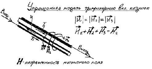
We have discussed here before, the fact that H3 is H3 simply because H1 and H2 cancel out: H1 + H2 + H3 = H3, why is this so, because H1 is Positive and H2 is Negative! We have seen this equation before: 1 + -1 + 1 = 1.
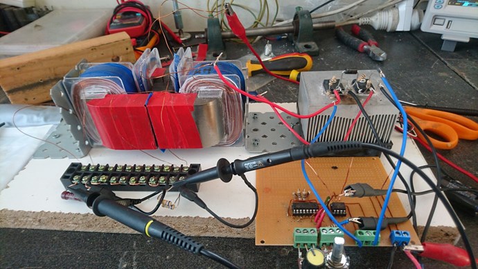
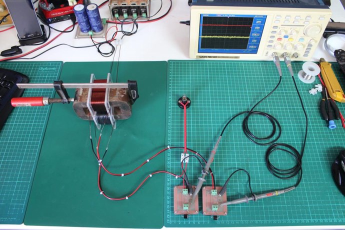
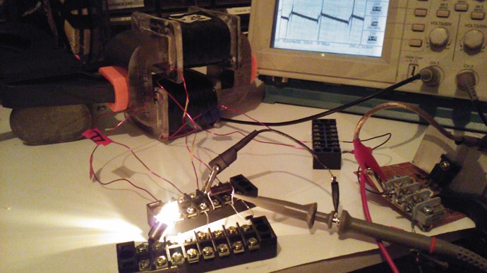
I think with Fighter's success recently, its time for some hands on!
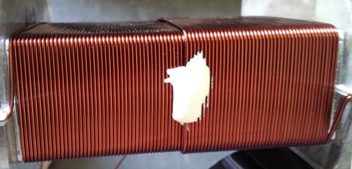
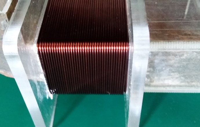
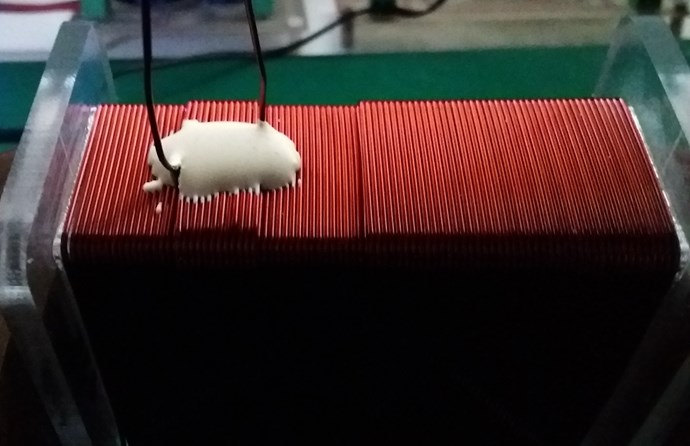
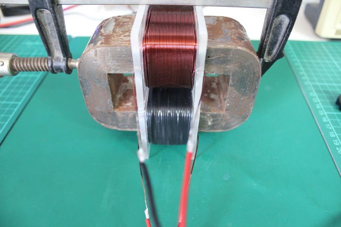
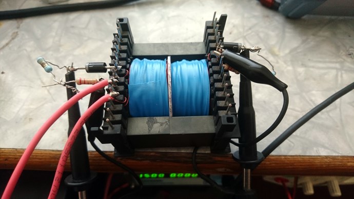
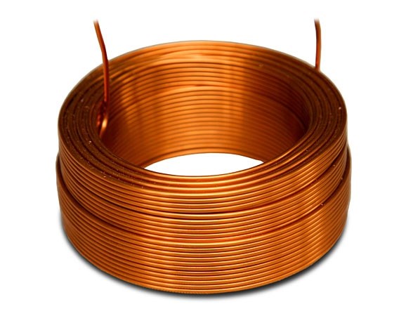
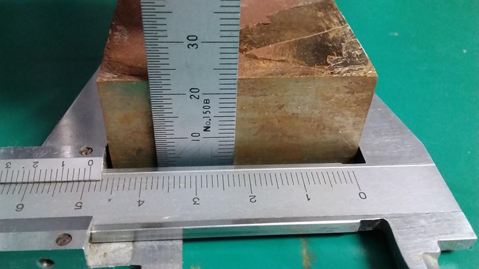
- First Layer: 88 Turns.
- Second Layer: 43 Turns.
Layer One:
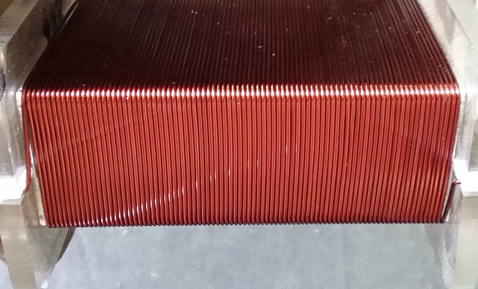
Layer Two:
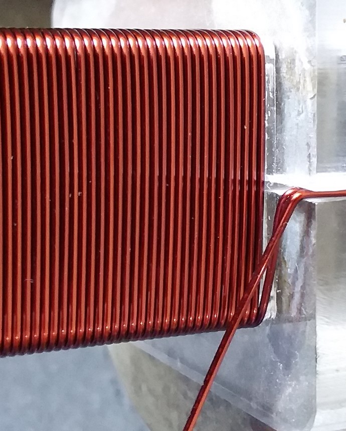
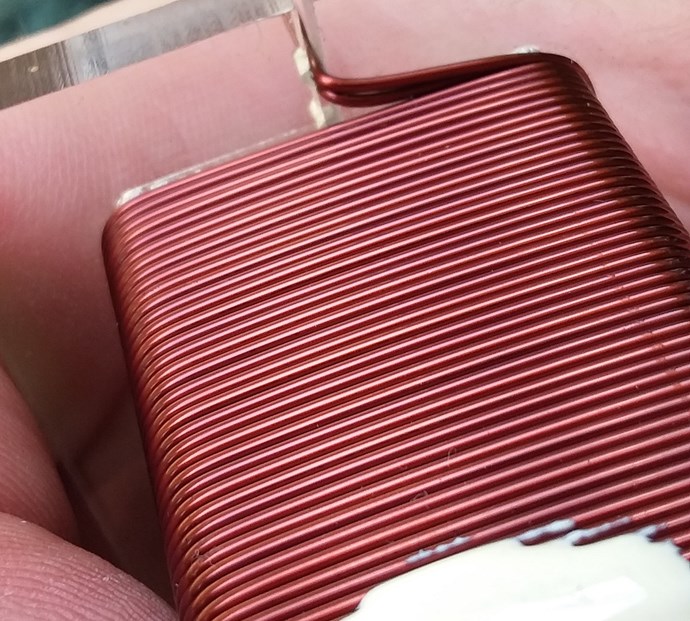
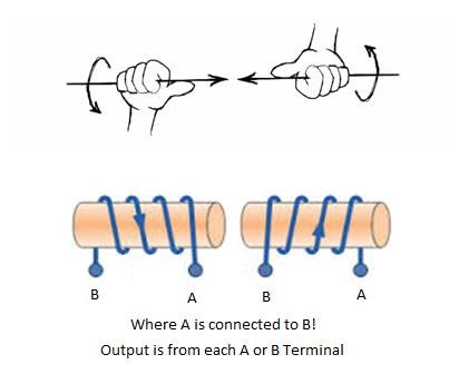
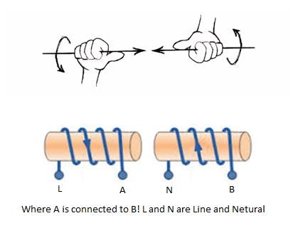
Turns Direction:
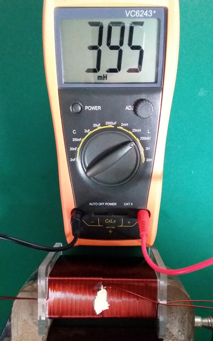
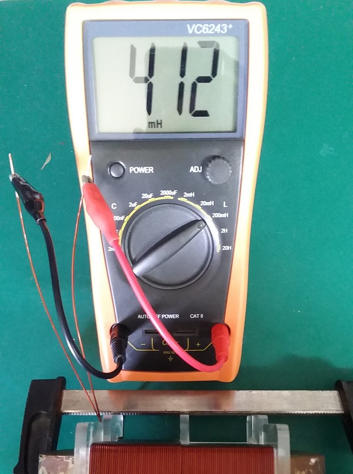
Layer One Inductance:
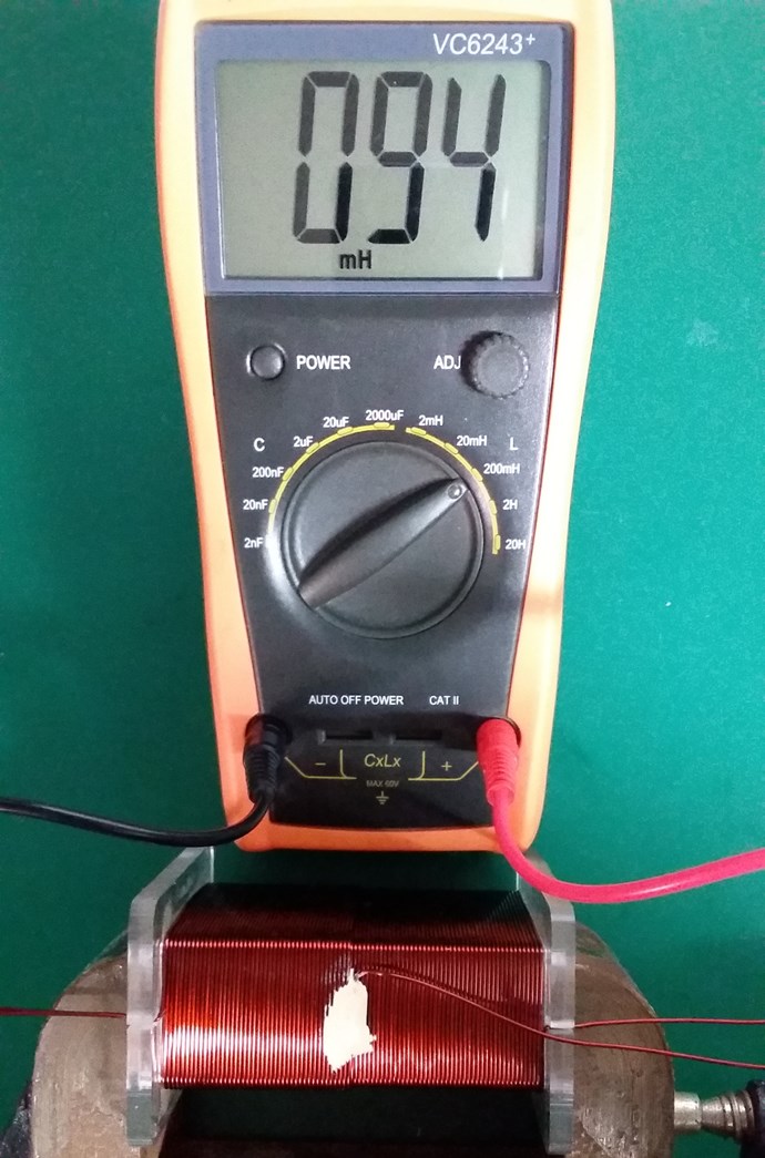
Layer Two Inductance:
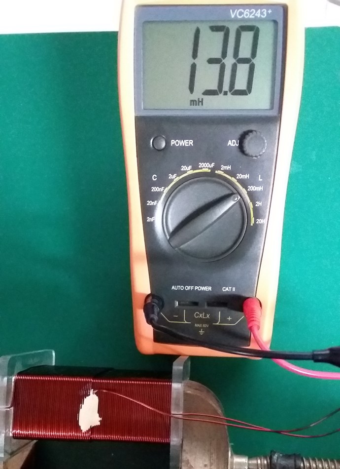
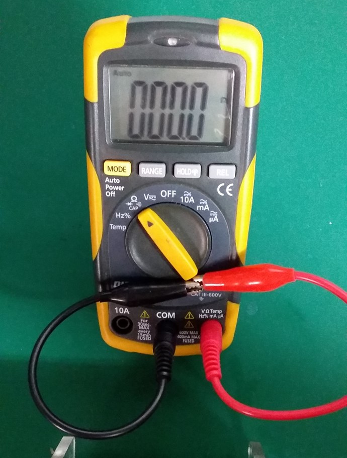
Non-Inductive Connected:
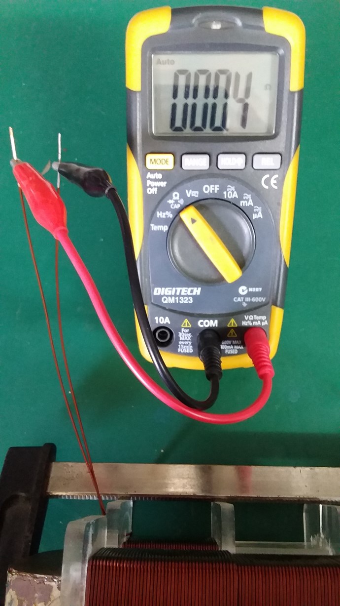
Layer One Resistance:
Layer Two Resistance:
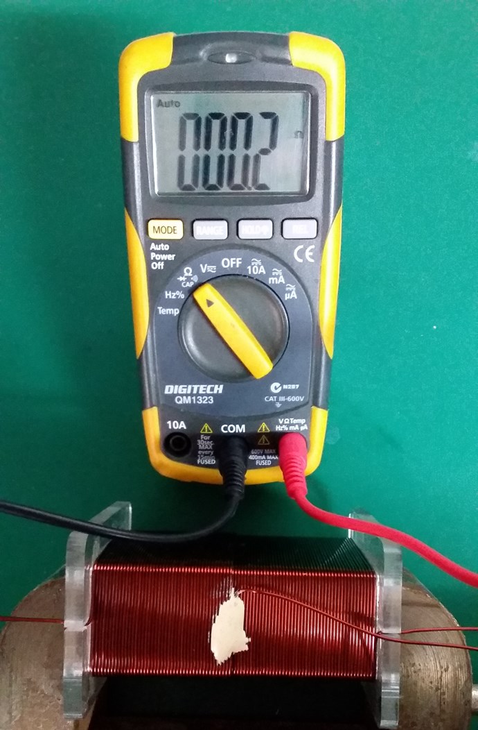
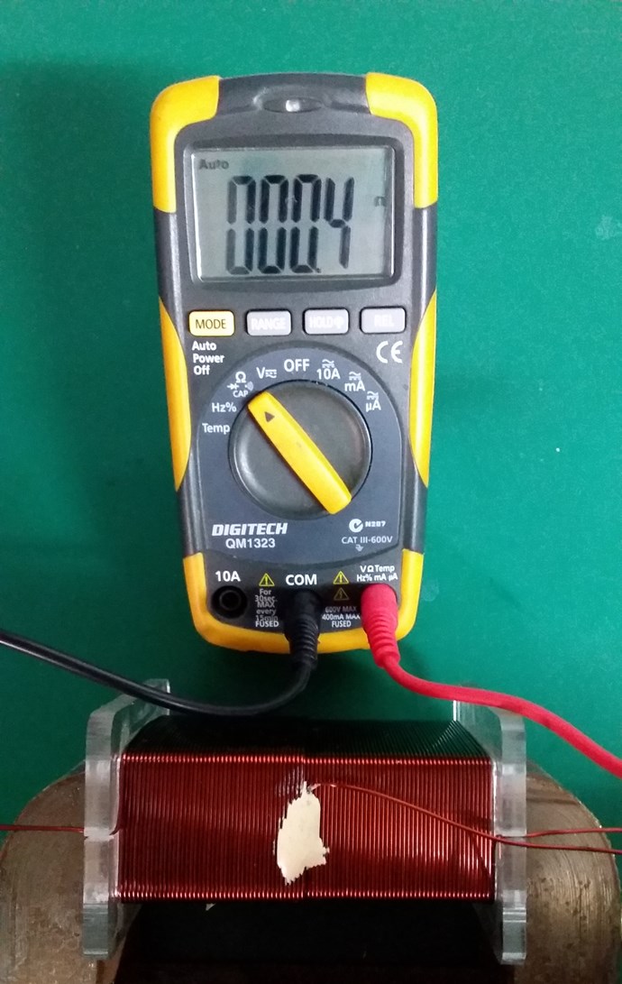
Closed Loop Resistance:
My Coil, like Andrey Melnichenko's, is 0.33 + -0.33 + 0.33 = 0.33.
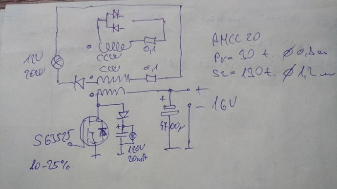
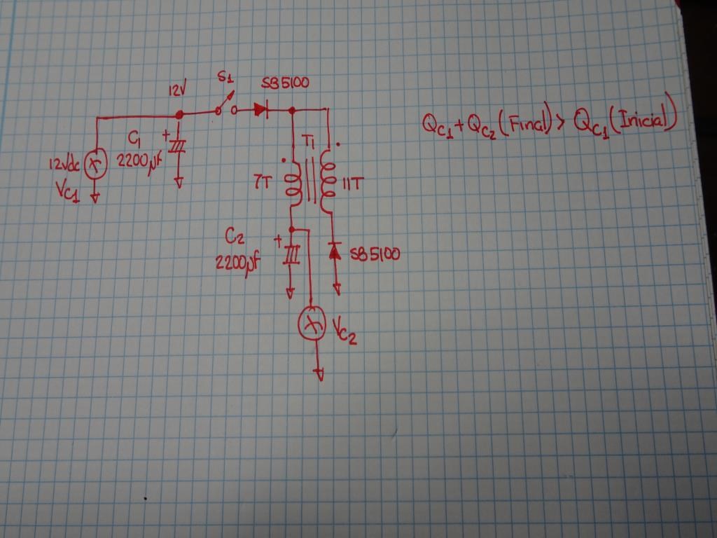
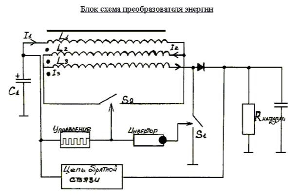
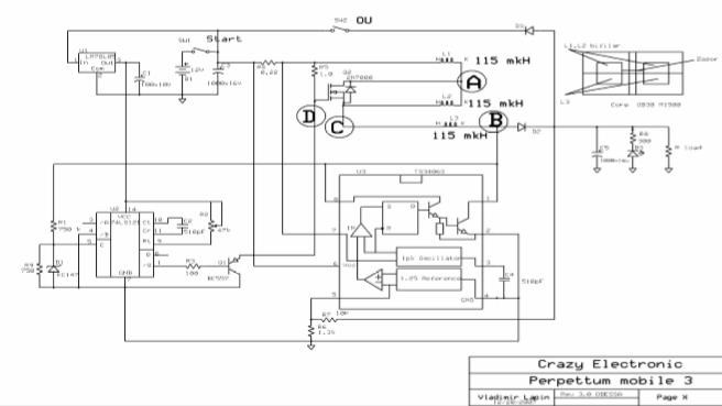
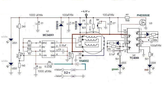
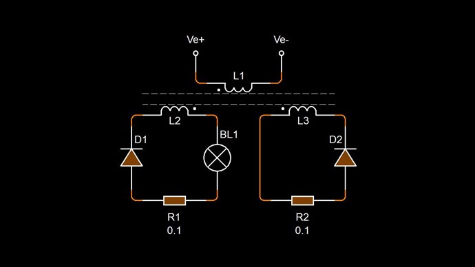
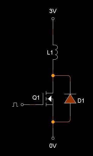
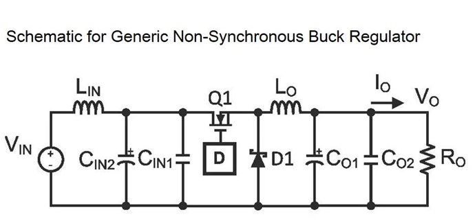
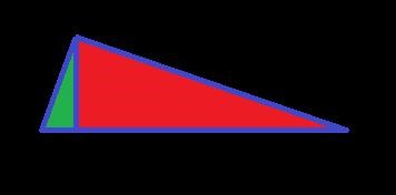
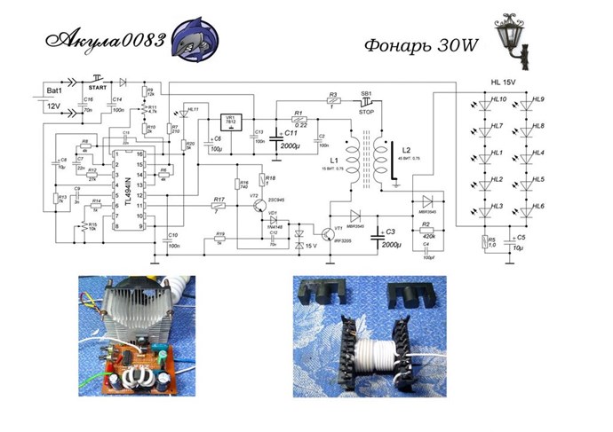
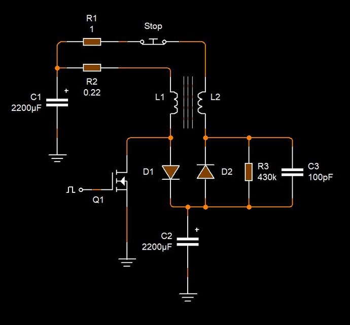
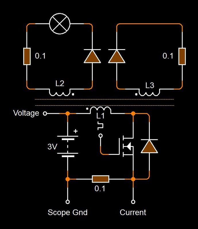
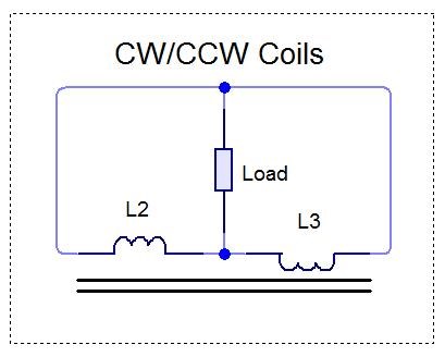
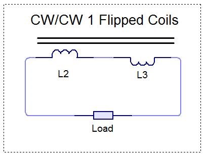
Two thirds of my Coil is canceled out. My Circuit looking like this:
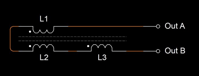
Where:
- L1 and L2 are Non Inductive.
- L3 is Inductive.
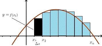
If this Coil is carrying 1 Ampere of Current, and exactly one half of the Coil is Non-Inductive, then Turn for Turn, only 45 Turns will create an M.M.F, which is considered as 45 Turns x 1 Ampere = 45 Ampere Turns or 45At.
Science tells us, that Turn for Turn, where we have Non-Inductive part of the Coil, this part of the Coil does nothing! Creates no Magnetic Field, therefore does nothing.
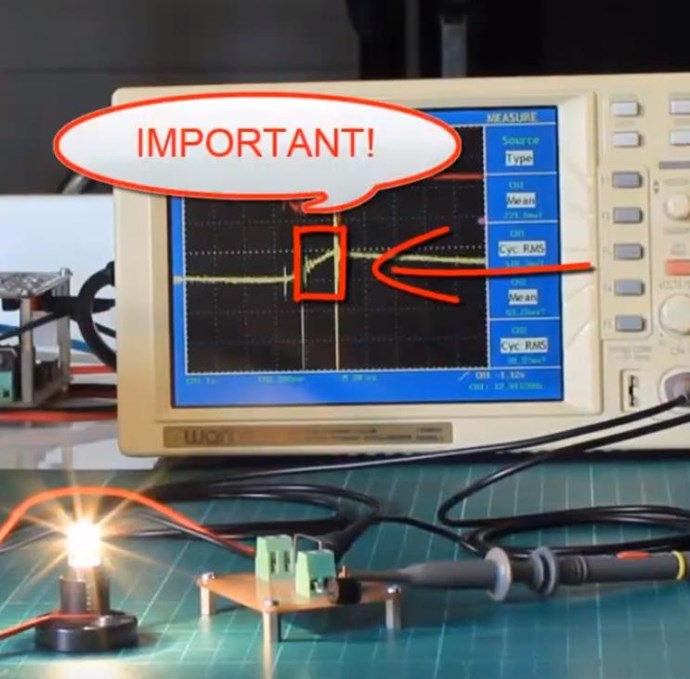
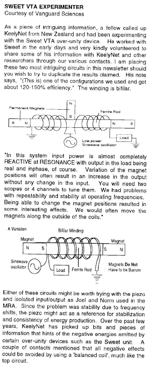
However, from Experiment, we know that this part of the Coil DOES do something! Remember Floyd Sweets paper: Nothing is Something, this is the same!
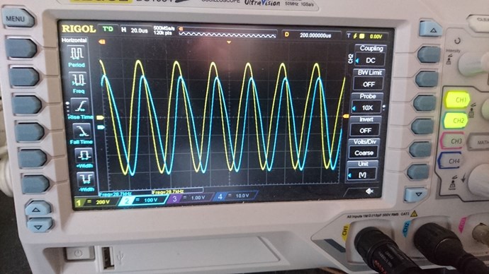
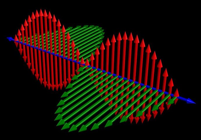
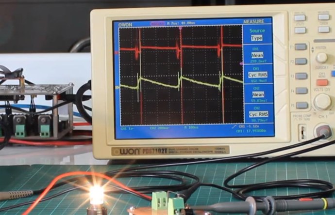
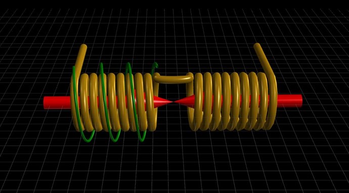
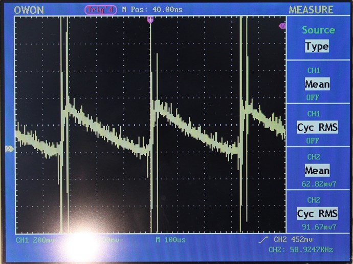
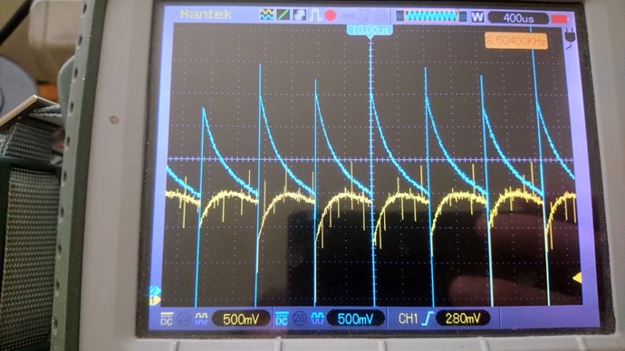
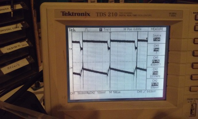
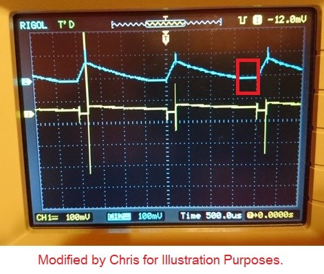
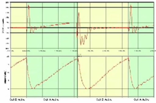
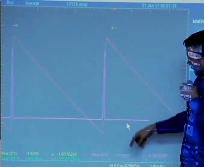
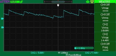
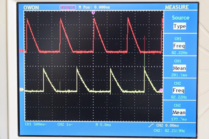
At Resonance, we have a perfect Standing Wave! We know this as Magnetic Resonance! Where each Magnetic Field is 180 Degrees out of phase:
Now, straight away, we should see a problem! Why? Kirchhoff's Current Law says the Current must be equal at every node, but we have Turn for Turn, one Coil that is Inductively Zero, and another Coil that has only a part of the Induction canceled!
In the specific case of positive charges moving to the right and negative charges to the left, the effect of both actions is positive charge moving to the right. Current to the right is:
I = da+ / dt + da- / dt
Negative electrons flowing to the left contribute to the current flowing to the right.
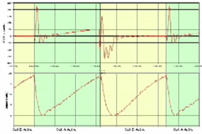
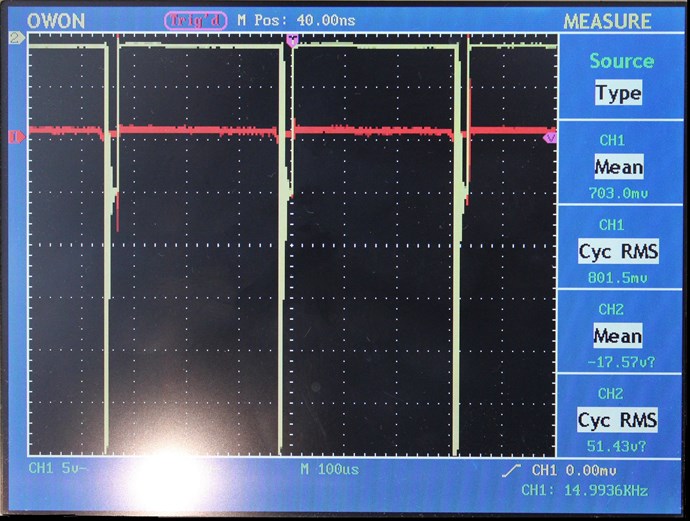
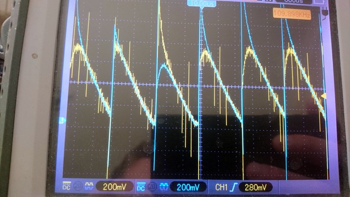
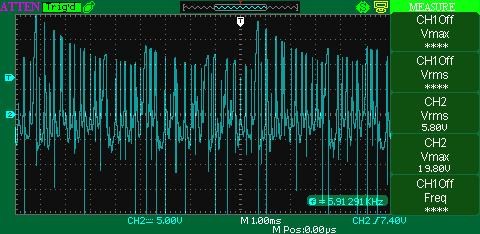
Each node does not equal the other, so the Circuit must balance out, Current is Increased as the Standing wave shows us.
Remember what Induction is? See here: Non-Linear Inductance
Induction gives us an approximation on the Coils ability to carry a Current: L = ε / di / dt
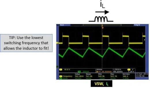
By Bringing a Coil arrangement like this into Resonance is our task.
Where each Electromagnetic Wave travels in opposite directions. One through the other in the same space.
THE NATURE OF SPACE
Space itself is the ability to accommodate energy. Consider for a moment the following illustration:
A signal (energy) is transmitted from point A to point B. A and B are separated by a finite distance. Consider three periods of time:
- The signal is launched from A.
- 2) The signal resides in the space between A and B.
- 3) The signal arrives at B.
If (3) occurs simultaneously with (1) we say that the signal has traveled at infinite velocity. The signal has never resided in the intervening space and therefore there exists no space between A and B. A is virtually at the same point in space as B. For real space to exist between A and B it is necessary that a signal travelling between them be "lost" with reference to both points for a finite period of time.
Now we know that for real space to exist between two points a signal travelling between them will propagate at a finite velocity c, ( c = 1 / √με ).
If a signal will not travel between two points, as in the case when c = 0, then we can also conclude that there is no link or intervening space between them.
Floyd Sweet tried very hard to make c = 0! What does this mean? It is simply a Standing Wave, a Team Wave was used:
It is a simple matter using the equations E / H = √με and c = 1 / √με for a team wave to get rid of H and c and so convert the first equation into the well known equation for energy density in the so-called electrostatic field.
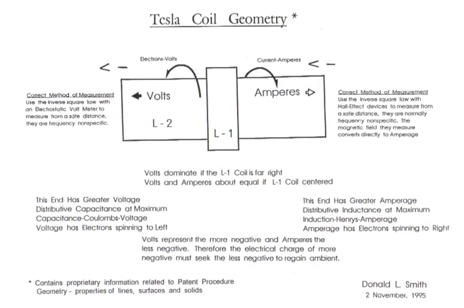
I have pointed out: Why 'C' is equal to One in these Devices.
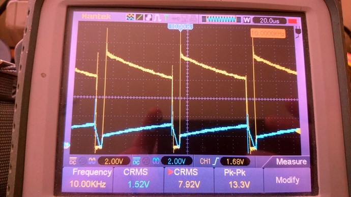
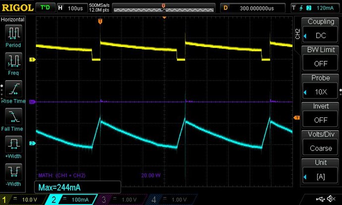
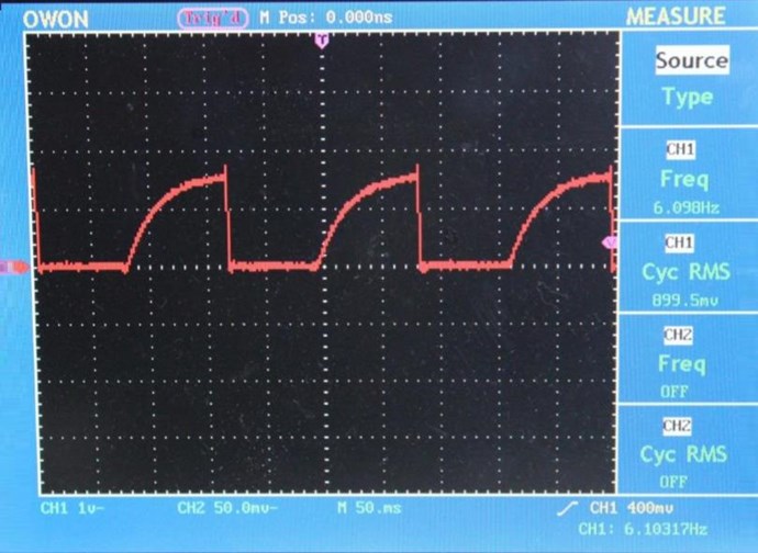
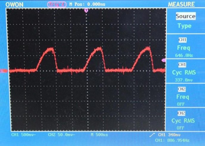
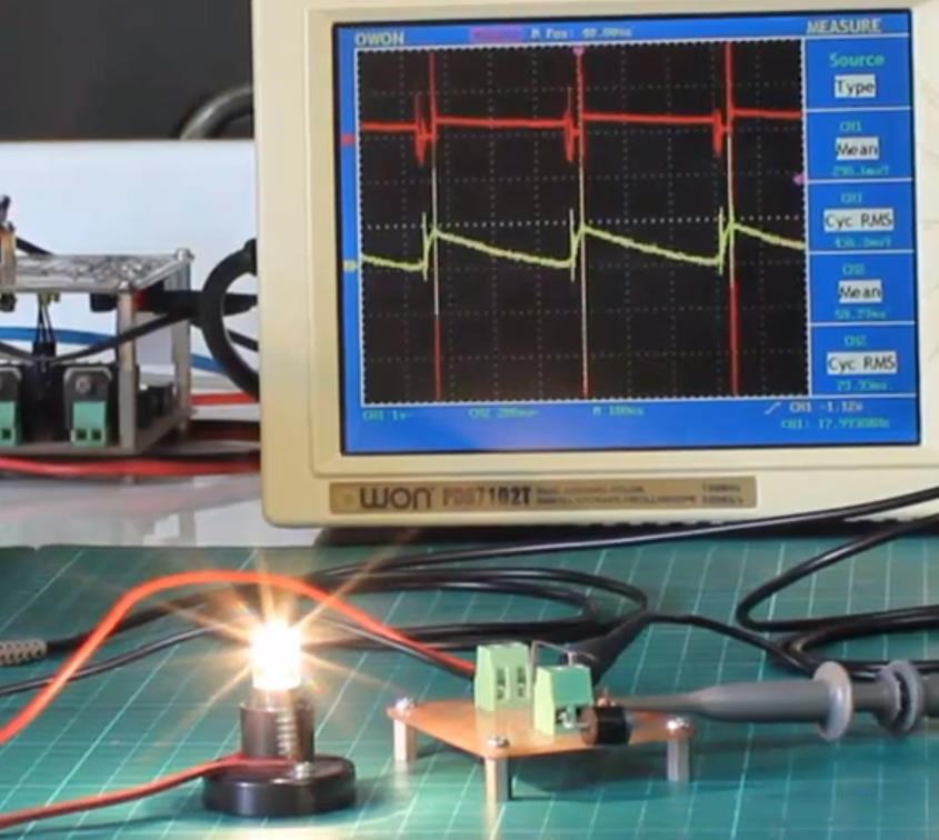
We have a lot of data!
Chris


 Sure buddy, you "did" a lot of research and put a lot of "effort" in renaming from "Romanian ZPM" to "Magnetic Delay Transformer", congrats !


 .
.


 . I think I can see


.jpg?width=690&upscale=false)


.jpg?width=690&upscale=false)