Partnered Output Coils

  • 13K Views
  • Last Post 05 January 2024
  • Topic Is Solved
Chris posted this 05 August 2017

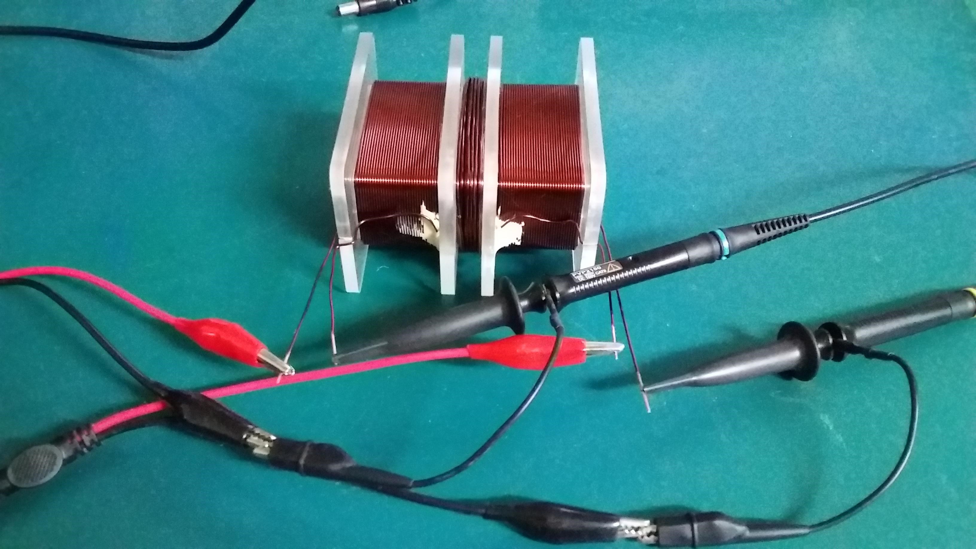
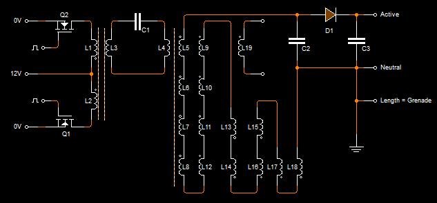
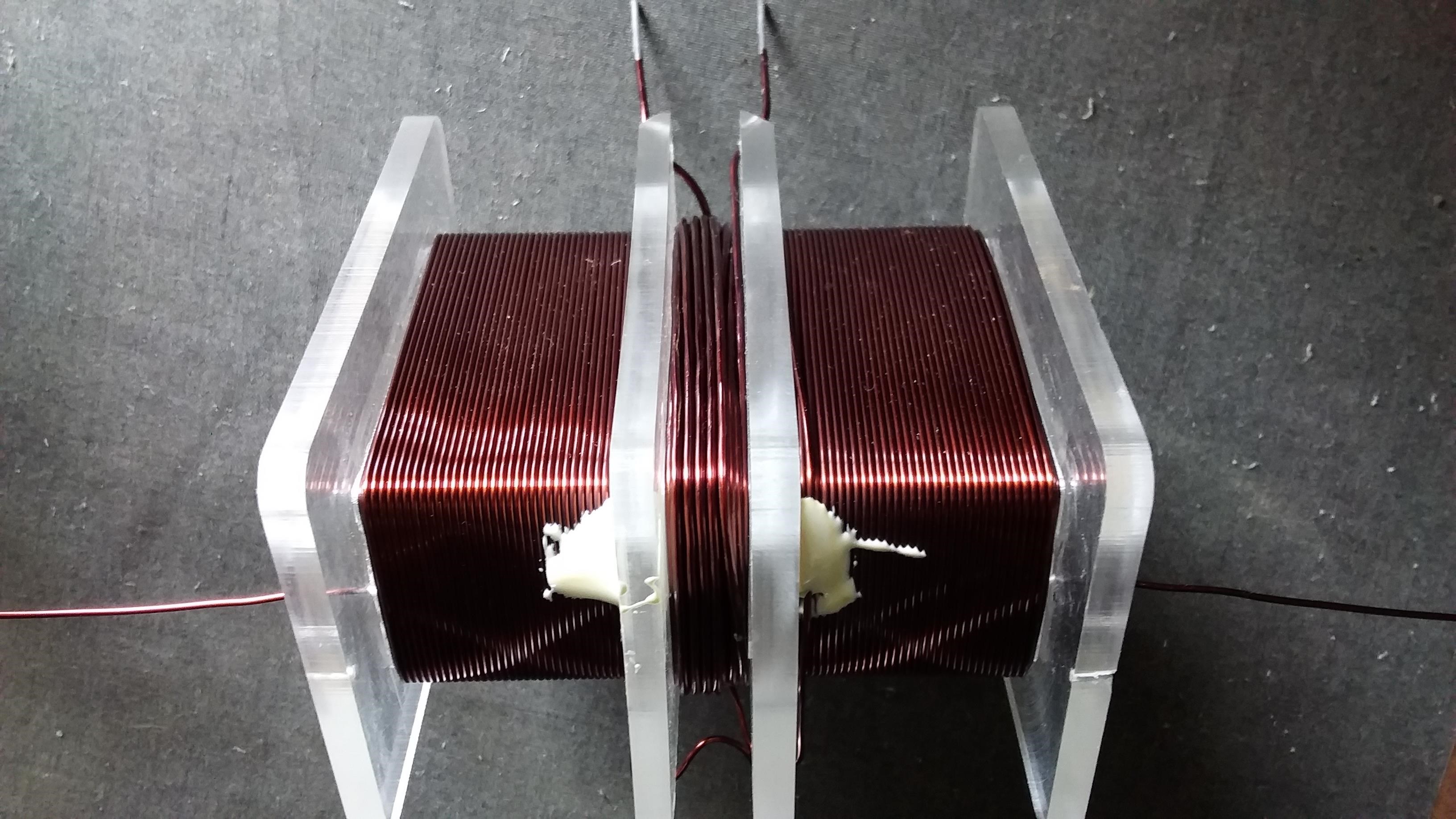
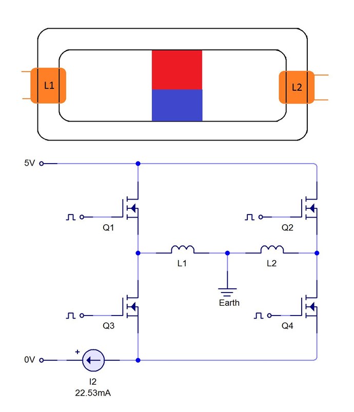
Many times I have talked about Partnered Output Coils. People call them Bucking Coils. I prefer not to use this terminology. Its a bit confusing. I use a Sudo Diagram:
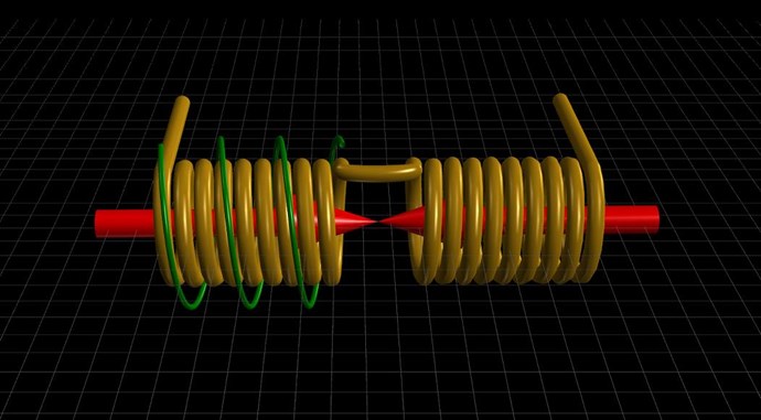
I have been through the "Common Mode Choke" and why Partnered Output Coils are different in the Timing Thread.

People in general seem to have a largely misunderstood inception of Partnered Output Coils, or Bucking Coils in general.

Andrey Melnichenko also shows a Bucking Component to his Coils. But the Coils were not Bucking as we think of Bucking.
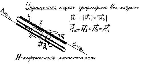
Here is an example of how it is a misunderstood area of Science. Itsu is an excellent Experimenter, this is not intended as a dig, just an observation:


Studding this video, it is obvious there has been a lot of effort gone into this. A lot of work! But Itsu is missing something, something that is the most important of all! Can you spot what it is?

His Grenade Coil is wrong! This also pointed out in the comments.

The Grenade Coil must have, what would normally be thought of as a "Non-Inductive" Component, a Bucking Component! Actually, we will find, as time goes on, this is Highly, extremely Inductive!
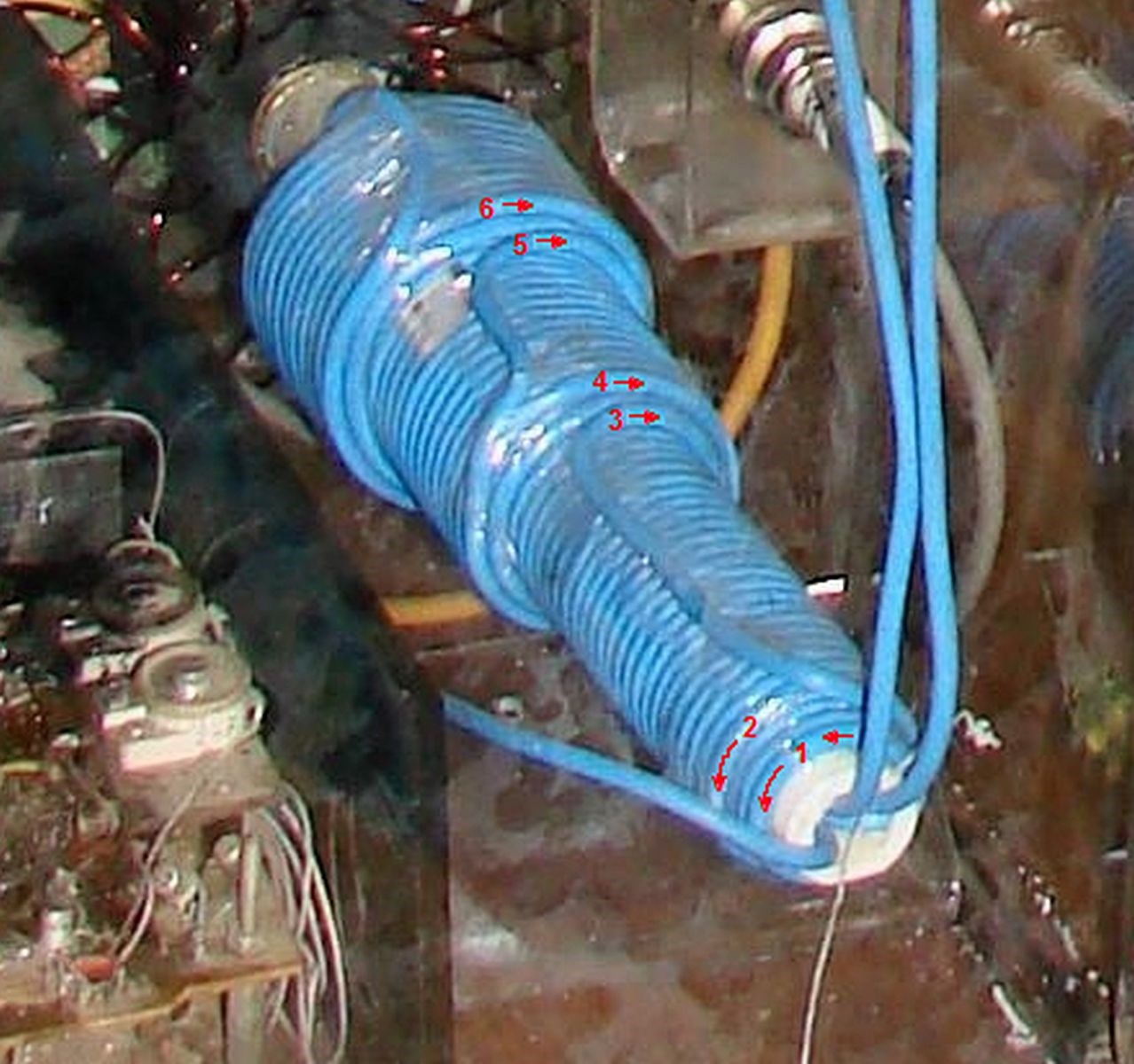
Turns 1 and 2 are Counter Clockwise, turns 3, 4, 5 and 6 are Clockwise. 
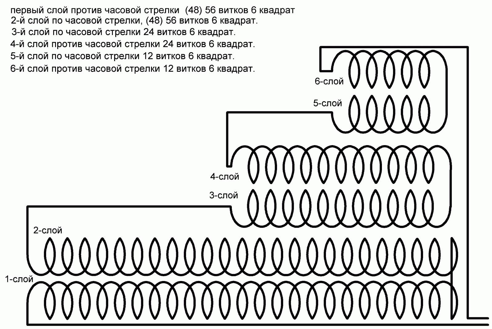
Ask yourself the question, how is it that a huge amount of Electrical Power can be extracted from a NON-Inductive Coil?

Also from Ruslan Kulabuhov
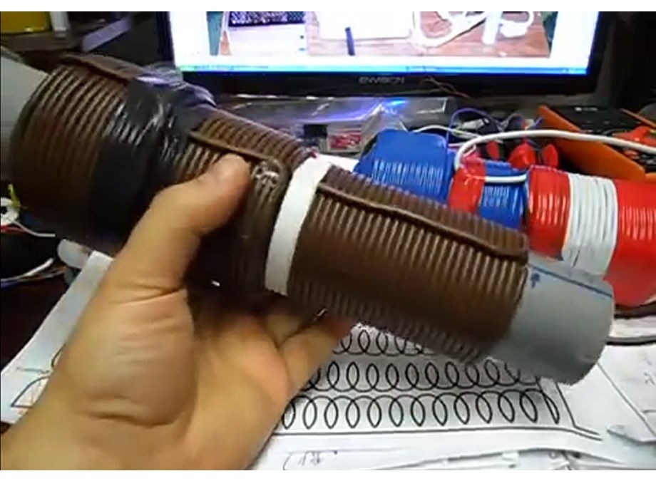
It is actually this Extremely Inductive Component that makes a Common-Mode Choke work as it does!

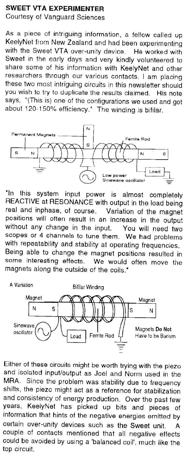
Floyd Sweet also shows this exact same Bucking of Magnetic Fields:
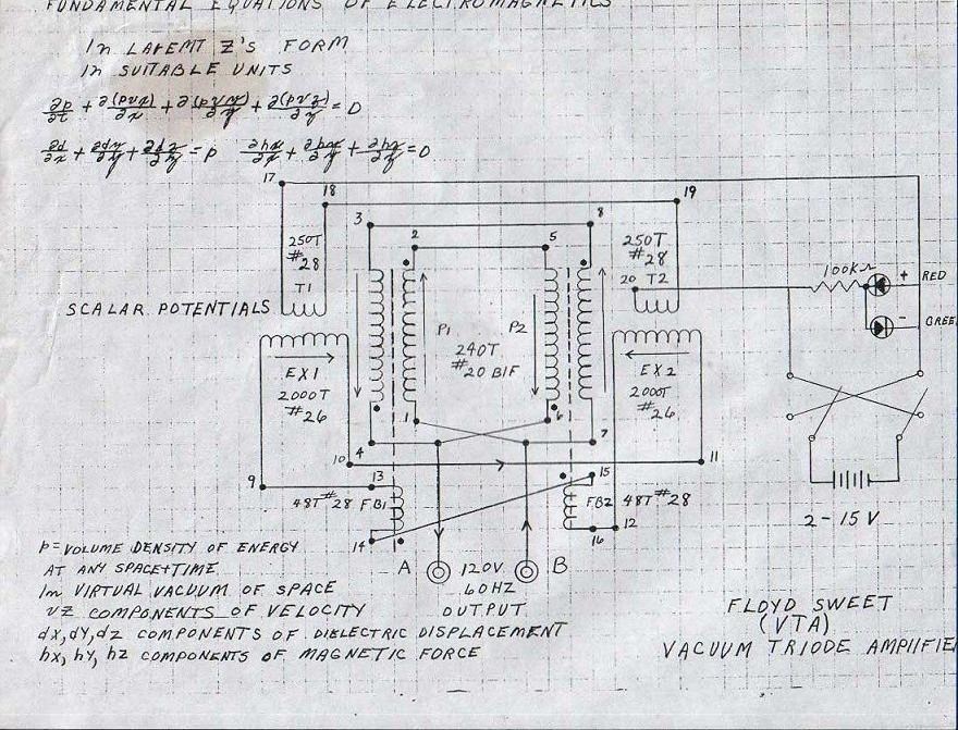
 

The VTA Description is as follows:

 Consider for a moment the construction of the triode which includes the bifilar coils located within the fields of the two magnets.


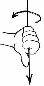
When the current in one half of the conductors in the coils (i.e., one of the bifilar elements in each coil) of the device is moving up, both the current and the magnetic field follow the right-hand rule.


The resultant motional E-field would be vertical to both and inwardly directed.


At the same time the current in the other half of the conductors in the coils is moving down and both the current and magnetic field follow the right-hand rule.


The resulting motional E-field is again vertical to both and inwardly directed.

Thus, the resultant field intensity is double the intensity attributable to either one of the set of coil conductors taken singularly.

Now, a Right Hand Rule both facing Inwards, it is the same as:
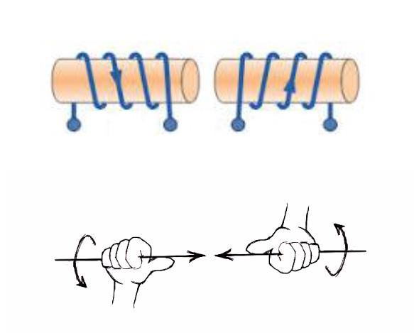
Why? Why must we have Opposing Magnetic Fields?

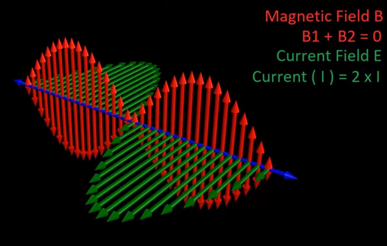
If the directions of the two signals are such that opposite H-fields cancel and E-fields add, an apparently steady E-field will be created. The energy density of the fields remain as calculated above, but the value of the E-field will double from E/2 to E.

By Opposing the Magnetic Fields in a Dynamic System, the Electrical Field doubles! The Mr Preva Experiment proved this to be true!

Floyd Sweet also said:

Current is deemed as a quantity or number of charged particles moving from P1 to P2 in time t, or as the charge transferred in one second by a current of one ampere. The coulomb is the charge on 6.24 x 10¹⁸ electrons. Electric fields are due to the presence of charges. Magnetic field effects are due to the motion of charges. Current is the net rate of flow of positive charges. This is a scalar quantity.


In the specific case of positive charges moving to the right and negative charges to the left, the effect of both actions is positive charge moving to the right. Current to the right is: I = da+/dt + da-/dt. Negative electrons flowing to the left contribute to the current flowing to the right.

The Mr Preva Experiment also proved this to be true!

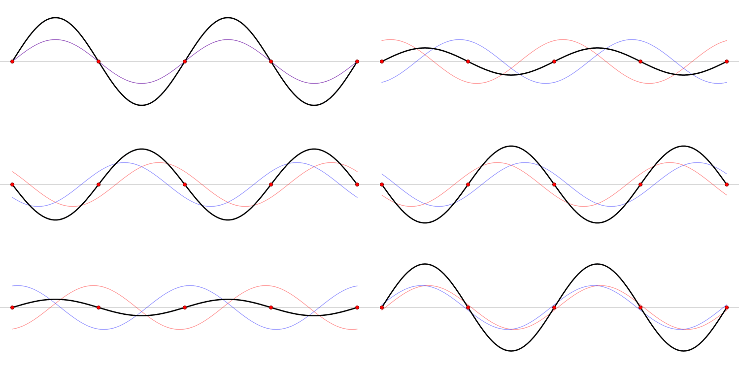
We see a Standing Wave of Magnetic Fields! 

 This thread is for those with questions, thank you Vasile for the following question.

   Chris

Order By: Standard | Newest | Votes
Chris posted this 08 August 2020

My Friends,

We have made great strides ahead! For anyone following, if you stop and look back for a minute, only a year ago, you will see great progress made!

We have learnt the basic requirements inside out now:

  • Two Output Coils are required, or at least part Clock Wise and part Counter Clock Wise, but it is easier to think of two separate Coils.
  • We must find Magnetic Resonance!
  • We must increase the Voltage on the Output: Current I = Voltage V / Resistance R.
  • We must aim for Asymmetry, and avoid Symmetry entirely as Symmetry is not ever beneficial for us!
  • We have learnt that the Output Coil Impedance, can play a role in the operation of the machine!
  • We have some basic Math to help us aim for Machine operation, although it is not complete. Antenna Theory.
  • We have learnt our Input is merely a Catalyst for the Coil Interactions!
  • We have seen many replications from many different people, and we have learnt many methods for acquiring measurements for accurate Input to Output measurements.


Its been a long road My Friends and you all have stuck with me on this long road. I Thank You for this! It is you that is changing the world for the better! 

Right now, we are getting more visits and reads than ever before! People from every country around the world are taking notice of what we are doing and people are learning. This is key, this is the first step!

Best wishes, stay safe and well My Friends,

   Chris

Chris posted this 08 September 2020

My Friends,

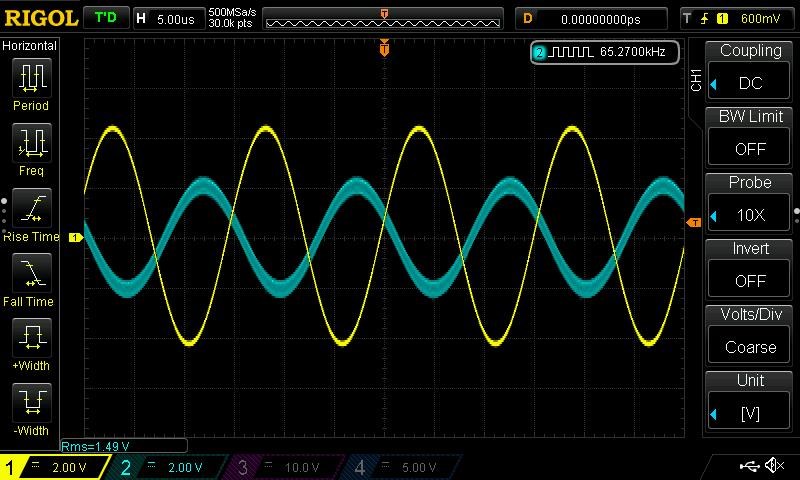
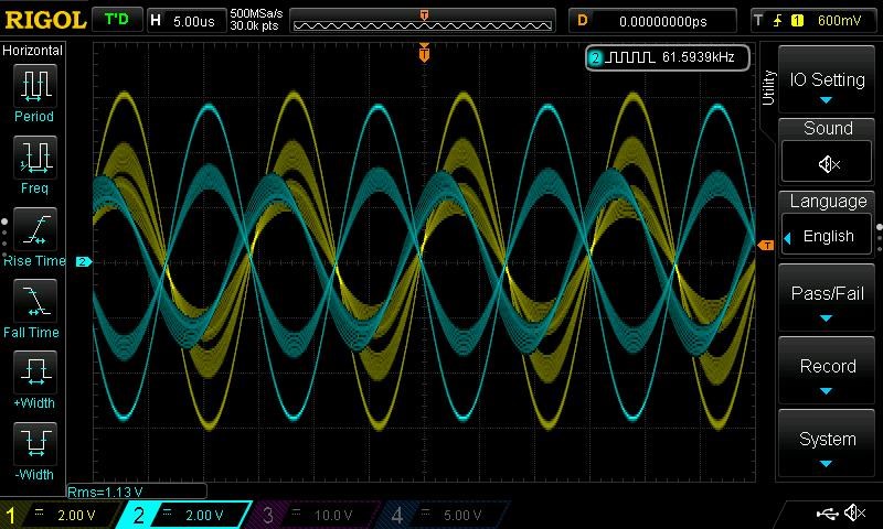
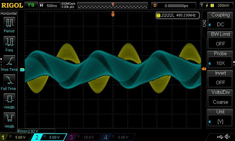
The below image, is Electromagnetic Induction, or if you wish, Antenna Theory, one coil only, with a single signal:


Note the Phase Angle, also the reduction in Amplitude from the Yellow to the Blue or Teal Waveform. Yellow is being driven, Teal or Blue is Induced Voltage.

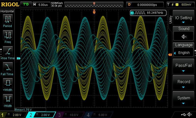
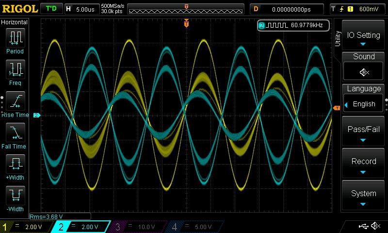
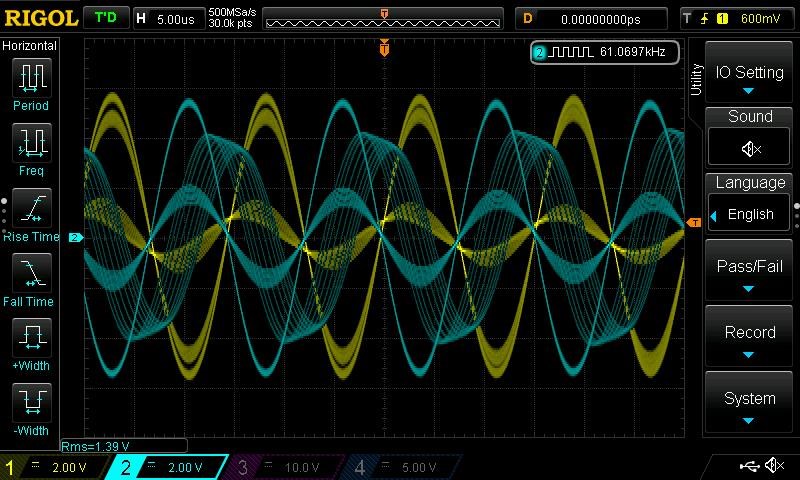
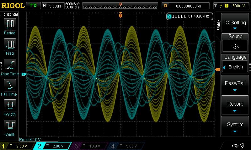
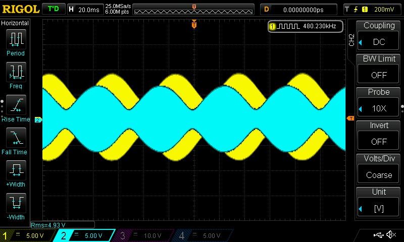
Some Scope Images with both coils driven in Resonance:


I guess the question is, whats the practical use of this? What is this showing? Of course its pretty to look at! 

The reason I show this, is because this is Open Circuit, no Current, Standing Waves!


There is no Brute Force here what so ever! This is purely a Resonance Phenomena!

Best wishes, stay safe and well My Friends,

   Chris

Chris posted this 14 November 2022

My Friends,

I read a post on another forum today, which I feel needs to be bought up here!

It is from Member Smudge:

I think the Mark referred to in that letter could be Mark Goldes.  He ran a free energy organization Magnetic Power Inc. (MPI).  Mark was a good guy trying to bring free energy to the world but got a lot of online criticism because he was encouraging investors but never got them any monies because the free energy dream never came.  He mortgaged himself up to the hilt to keep the company going.  I think this alternator idea from Sweet was one of the things MPI put forward, but Sweet died before it got anywhere.  So maybe it has never been explored further than his idea put on paper.  I note that his current sensor started out as a helical coil wound around the primary conductor, but then changed to a ring core around the conductor (bizarrely stated as a hollow core in the diagram you posted) and the ring core has its own winding for the sensing output.  This tells me Sweet was developing the idea in his mind at that time and realized that the helical winding would not work.

Sweet made a number of fundamental assumptions or errors in his writings.  Perhaps the most striking is his statement in the image you posted that says "The rate of flow of moving charges may be accelerated beyond 1 ampere= 6.24x10¹⁸ electrons/second".  That would mean that the electron charge increases value.  Reading further on I don't think he meant that, but rather more charge is somehow entrained from the copper atoms so the number of conduction electrons increases.  Whatever was in his mind it is beyond what current science will accept and F6 would have a field day criticizing this.  Personally I would agree with F6, this is fanciful dreaming by Sweet.  Another of his errors claims that space has a frequency given by f=1/(2π*sqrt(μ00)).  This is of course nonsense, that formula merely gives you the frequency for which the wavelength is 1 meter.

Mark Goldes received a number of hairbrained ideas from different people, and he recruited me from another FE site to become an unpaid adviser.  MPI was later taken over by Hagen Ruff who then continued its work under the guise of Chava Energy and I was pleased to continue as a paid consultant.  Sometime later Hagen decided that pouring money into FE research was not going to provide any short-term returns, so he pulled the plug and my contract ended.  Chava continues offering not free energy but alternative energy solutions like wind generators.

Smudge

Ref: Floyd Sweet 'Space-Flux Coupled Alternator' (NOT the VTA)


Mark had about 10 organisations!

I think it is worth noting, Smudge has always played down Floyd Sweet as have many other of the people that were involved with Floyd Sweet! There is a number of non-sensical statements in his post!

Let me quote Floyd Sweets paragraph again:

The current and potential windings require relatively little power, and are applied in such a manner that rate of flow of moving charges may be accelerated beyond 1 ampere = 6.2418 electrons ⁄ second. Thus the duty factor of the copper changes. I2R Losses diminish and more charges drawn from the now coherent space field flow at a faster rate as current to the load. This means as more current is required by varying loads more feedback magnetomotive forces free more electrons from binding forces complimented by potential magnetic forces of the orientated, coherent space field. Thus a conductor that formerly had a temperature rise above ambient labelled as a factor of 10 would now operate at a temperature of 1.0. Thus the same gauge wire would carry 10 times more current at the same temperature.


Now Smudge states:

That would mean that the electron charge increases value


I absolutely disagree with this statement! This is simply a very bad interpretation of a very basic Statement made by Floyd Sweet!!!

Water Pumps have Flow Rates, in GPM, Gallons per Minute, or LPM, Liters per Minute!


Electromagnetic Charge Pumps are exactly the same, there is no ignoring the basic Science and Math! Elementary Charge also has a Flow Rate!

The definition for One Ampere is:

6.241509074×10¹⁸ elementary charges moving in a second.


I see a real concerted effort to try to confuse and smear the hard work that those before us have done!

Don Smith told us the very same thing:


Let there be Twits! Let the twits be a mouthpiece for Non-Sense! 

Did any of Akula0083's work ever see the light of day?


Was there a cover up and an effort to burry his work? What happened here? 

My Friends, you need to be very careful what you believe! Some people will lead you down the Garden Path and you will find out after a long time, that there is nothing but Manure at the end!

Floyd Sweet said:

A static version of the Space Flux Alternator is on the drawing board. 


and went on to say:

The defining equations are similar to those of the dynamic Space Flux Coupled alternator. 

...

As the time varying flux of a period of 1/400 or 2.5 milliseconds sweeps over the stationary armature coils, voltage is induced defined by Faraday's law. 

...

The underlying principles are the same. 


Best Wishes,

   Chris

Chris posted this 11 August 2020

My Friends,

Another example of Wave Theory in these machines is from Don Smith:


You will note, Don Smith's turns is an indication:

  • 16 Turns on the Partnered Output Coils.
  • 4 turns on the Input Coil.


Mathematically: 4 / 16 = 0.25 or Quarter Wavelength. This means, for 100 Turns on Each POC, the Input Coil is 25 Turns.

Best wishes, stay safe and well My Friends,

   Chris

Chris posted this 02 September 2020

My Friends,

I feel we are not focusing on the Electrical Energy "Generation" aspect enough. Especially for new comers. For all Members, I am sorry you have read this many times and are no doubt sick of this!

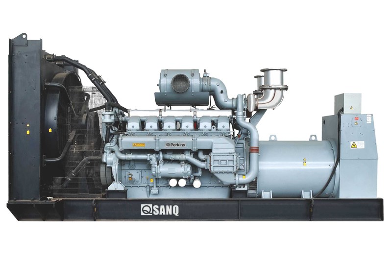
Shaft Torque, the difficulty to turn the "Generators" Shaft, when Loaded is a Force equal to the Electrical Output minus losses. So always a Below Unity System, Symmetrical. We see very large Combustion Engines driving "Generators" for this reason:


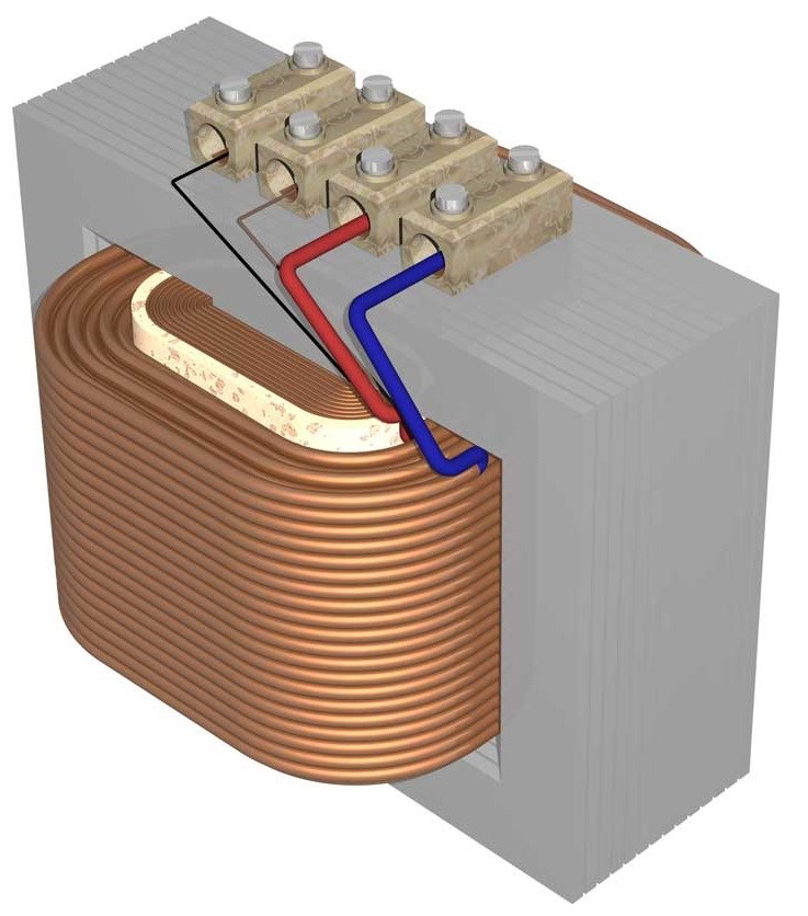
The same is true of the Conventional Transformer. The Primary Coil is opposed with Equal Force minus Losses:


We Humans are normally a smart bunch, when we see a problem, we normally work diligently to solve the problem! In this case, 189 odd years have passed and we have not made any progress! Well sort of...

Partnered Output Coils are designed Asymmetrically. This means, the above Symmetrical Opposition we see, is absorbed into the two Gold Coils, as Symmetrical Equal and Opposite Magnetic Fields, Equal and opposite Torque:


The green Coil, the Input Coil is the Asymmetrical component, bring the Coils into Magnetic Resonance only. Now for an example, if we are able to Reduce "Generator" Shaft Torque to Zero, then the Electrical "Generator" would be an Above Unity Machine! The same is true for the Conventional Transformer, if the M.M.F that if directly reflected back on the Primary Coil was some how circumvented, then the Conventional Transformer would be an Above Unity Machine!

Well, using Asymmetry, using Partnered Output Coils, this is what we have done!

Using very simple methods of Asymmetrical Regauging, we are able to Invoke magnetic Resonance between the Two Partnered Output Coils, in Gold, for a very short sharp pulse on the Input Coil in Green.

Like a Chain and Pulley System Counter Balances the weight, or a Crane Counter Balances Weight, we are doing the same thing.

My Series: Chris Non-Inductive Coil Experiment shows how to find and resolve problems and do exactly what I am saying above.

In an Electrical "Generator", if we are able to counter Shaft Torque by 20%, and the Machine is 90% efficient, then we have achieved: 110% or COP = 1.1, its simple, nothing difficult in this understanding. Of course, getting much more than 20% is the Goal!

This is the reason the Partnered Output Coils must Oppose!

Best wishes, stay safe and well My Friends,

   Chris

Chris posted this 04 September 2020

My Friends,

A video I have of Ruslan Kulabuhov, shows exactly the Wave and Anti Wave Pairs to make a Standing Wave:


Today, I am sharing a very simple experiment, showing the wave of each Coil and how Partnered Output Coils Interact Together:


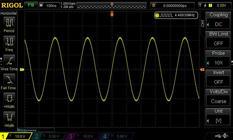
Scope Images of the Waveforms:


We get closer to an over all understanding and this video is one of the best yet. I have used, two of the following circuits to make this work:


Of course, I am using a different Frequency: 480.230KHz and 480.2499KHz. This setup gives us the effect I have shown before:


NOTE: My Frequencies I am using are different from my Above Experiment Here. I will explain this in up coming videos. Most of you know, its to do with Harmonics. Seems to be the 9th harmonic from what I can tell, not %100 yet however.

I hope this helps others to understand the Coils better!

Best wishes, stay safe and well My Friends,

   Chris

Chris posted this 07 September 2020

My Friends,

In light of recent events and personal attacks, I have decided to make the Video on resonance, Unlisted, available to only members here. Much of this information is not only sensitive, but also something I do not wish to share with those that would not help and be productive with us.

We have forces that fight against us and our effort! I have tested waters, and there is still a lot of effort to suppress us! To stop this information coming out!

I will always do the best I can for you, Members of Aboveunity.com!

Ask yourself, what does it take for something to withstand the rigors of Time?

We have shared the links to The Black Sun, and the Yin Yang symbols:


We have shown that these very important Symbols have stood the test of time are are directly linked to Technology we are exposing to the Public! Technology that some do not want you to have!

Please understand, change does not occur over night and we must be careful with what we do! We must be smart with our steps forward, we must look after all members and make sure they progress on an even footing as they choose and have time! Because, without them, we can not succeed! It is only in numbers we can force the hand of those that have suppressed this technology and expose them for what they are!

Best wishes, stay safe and well My Friends,

   Chris

Chris posted this 09 September 2020

My Friends,

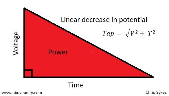
What do we think about when one says Pythagoras? Do we think of a Right Angle Triangle? The Pythagorean Theorem:


Is this what The Shark, Akula, gives us here: ( 2 : 25 ) Above Video.


There should be enough information to make special reference to the Sawtooth Waveform, making sure special attention is paid! I have said, The Sawtooth Waveform is the defining Energy Waveform.


Remember: I = V / R so increasing the Voltage, increases the Current! Voltage is Free!


We must Pump Electrons down the Wire, and there is only one way to do this! We already know how to do this!

Best wishes, stay safe and well My Friends,

   Chris

Chris posted this 08 March 2023

Hello Donovan and Friends,

Yes, there is a lot of data here on this forum, and some have used this data to make excellent progress!

I have collected all the data and posts from many forums over the years and I estimate about 3% of the Community are Serious Dedicated Researchers!

That's a very poor number!

Many run multiple names!

The fact of the matter is, majority of the community has been controlled disinformation for decades and I don't think any one would disagree with that! Groups of people paid to make a mockery of the Energy Field for a very long time, and yes I have a list of names when the time comes.

ChatGPT:


There are a lot of very brain dead people out there, doing the dumbest things, sadly! ChatGPT is very much smarter than these idiots! Even if ChatGPT is not completely correct!


Best Wishes,

   Chris

Chris posted this 15 October 2023

My Friends,

In regards to my last post, in this thread, I want to explain something very important, something I have explained before, but no one has touched upon, except one person, which I will not use his name for the moment.

I have pointed out, before, in the Thread: The Reduced Impedance Effect, that we can have a situation, where all of the Coils Impedance can be removed, from a machine, simply by clever design techniques!

What does this mean?

Very Simple, this means an Electric "Generator" can be designed that has no Drag on the Shaft! This concept extends well beyond just the Electric "Generator"! This Concept can be applied to all EM Machines, all of them! 

The Conventional Transformer is another machine that can have this Concept applied to!

Like I pointed out in the last post, the concept of Drag is removed from the Asymmetrical Machines I have shown you:


NOTE: No Drag as we know it, means that the Potential we can achieve can be achieved very much faster than we would normally expect, because we are essentially not fighting against a Magnetic Field. We are using Magnetic Fields to Cancel, or Control Magnetic Fields.

Some would say we have Negated Lenz's Law, technically, this is not an accurate way to view the situation, but its how many have thought of this. We are using Magnetic Fields to do more work for us in a single machine, than is conventionally thought possible, because we are using Asymmetrical Electromagnetic Induction, a concept that Science has not been able to explore at all, because Science Establishment is too ignorant and arrogant to accept that they entirely missed it!

Here is some advice I posted via PM, to a member here, I normally don't get any time for PM's so I ask all to post in your own threads, and I will help:

some advice:

  • Treat your Input Coil and POCOne as a simple Conventional Transformer.
    • In a simple Conventional DC Transformer, the polarity of each Coil is determined by Electromagnetic Induction and Lenz's Law. The Phase is always 180 Degrees, represented by the Negative sign. So if you were to take two parallel wires, the Polarity would be opposite.
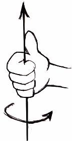
  • POCOne and POCTwo oppose and you can use The Right Hand Grip Rule to ensure each Diode is orientated correctly.
    • The Diode Polarity in the Circuit with POCTwo, will Increase your Input Coil's Current in one Polarity, and reduce your Input Coil's Current the other Polarity. We are aiming for Input Coil Assistance! To Lower your Input Coils Current is the Goal!
  • Ensure each Circuit on POCOne and POCTwo are isolated and kept separate until a greater understanding is obtained.
    • Have one Circuit for each Coil, manage each Circuit as required, to make steps on improvement as required.


Each Coil is always abiding by the Right Hand Grip Rule because Lenz's Law holds. If you look at each Coils Polarity, you get: Positive + Negative + Positive, and here you can see, we have a System that has an extra Input, an extra assistive force, which is an open System, allowing for Gains Above Unity!

Maximize your Machines Bucking, make the Machine Pump Electrons from the Atom, stripping away all the Electrons from the Atom if required, and Accelerate them down the Wire as a Current, where One Ampere = 6.241509074×10¹⁸ Elementary Charges per Second.


Each Partnered Output Coil is like a Battery! Each Coil must always Buck Each Other, and all you have to do is get the polarity of the "Generated" Voltage Correct!


This is so simple and its so cheap, and there are so many stupid ignorant idiots in denial, its so funny to watch these Idiots Squirm and Lie, each sentence they post, they keep making Idiots of themselves!


Very Simple, the Magnitude of the Magnetic Field of each Partnered Output Coil must be approximately Equal, and Opposite, then, when you achieve this, amazing things happen, things that the very same Idiots I mention above, have told you for many decades, cant be done, sadly! These people will become Enemies of the people very soon! They will become the Hunted very soon! Good People will start holding them accountable very soon!

The other forums don't cover any of the basics, so how can they have any direction? When they are unaware of the basic, simple principles, we hold dare and require to gain an understanding! Duuuurrrr!!!

Best Wishes,

   Chris

Chris posted this 06 August 2020

My Friends,

Today I explain with some help from one of my favorite personalities, Ruslan, finding the resonant frequency, and breaking the Coils down to the smallest possible components, in other words, Diakoptics:


I was not going to post this video, thinking it may not really be of much use for most here, as this is mostly known already!

I ask you, please review the last Post i quoted from Ruslan:

Kind time of day. Maybe here we will find a common language. At once I will say that I do not sit at forums much. No time ! However, now for the 5th time I am collecting Akulin for a capacity increase. There are ideas .... But in fact the people are looking for a bit of everything is not right. All these systems operate on the basis of standing and traveling waves. It is necessary first to catch the motion of particles in the coil. Those. as Kapanadze does with a tester or an ammeter. Only at HF frequencies no ammeter will help and you will need to catch an oscilloscope. The first rule: Wind the coil 40 meters. 2. Find out its resonant frequency (1/4 wave) Inductor 1/4 = 10 meters of the same wire (for example, 2.5mm) Connect the generator to a 10 meter coil, drive the rectangles at a frequency of 1 MHz and crawl higher until 40 meters do not appear sinusoid. The maximum amplitude. The generator is desirable to take a normal, laboratory! With output adjustment from 0 to 20 volts. We achieve maximum amplitude and move tenths of a kilohertz until it starts to dance. This is your wave resonance !!! We fix the frequency and voltage. It is for this all have to do the generators. Further ... Tesla we shake under this frequency that the effect has turned out. Then we do everything as I did or the Shark. In this case, everyone wants to repeat this device. Forward! We fix everything beautifully and stiffly, without forgetting that the resonance and effect can escape in the case of fastenings on the snot. We need to get the effect itself and work, and not a ready device. Once you begin to understand what to do next, you can already move. So .... Tesla, as we know, also wets the sinusoid. Suppose your frequency is 1.821MHz. The frequency, but alas. It is necessary to adjust Tesla on it. The shark used a critic between Tesla and the toroid (Antenna) over the inductor. This is just an accurate adjustment. It is needed before launching. Then the system holds and no matter what has slipped in not large limits. But! Again ... What where? On the Inductor we feed the signal of rectangles with a frequency of 1/50. Consider: 1820: 50 = 36.4 kHz pumping a rectangle through the junction (Pot) with 23-29 turns of wire 2.5 squares. I repeat, you need to make the voltage on this harmonic not 10-20 volts, but higher by an order of magnitude. Approximately up to 50-60 volts and get the same dancing effect at the output. Further ! Do not forget that Tesla does not need strong power. Do not let sparks run and wet so that it breaks through. This is not necessary !!! It's better to make a controlled Tesla. Continue: The output voltage will be 195-200 volts. This voltage will not be higher. Why? Later we will return to this. It is necessary to rewind the transformer-reactor (Coil) so as to obtain the desired voltage. This requires experiments. Remember that we push the current in the reactor with a transverse wave. Created by Tesla. In the coil another wave is formed under the action of pumping by rectangles. The particles of which constantly rotate left and right. By giving them the movement of the pulsating Tesla, we disperse them in the very conductor. This is a gemmoroid understanding, but a fact. Tesla must operate in one half-cycle or one arm of the transistor. It is advisable to manage the Tesla pack - pulse generator. When everything is clearly adjusted, you will see how the effect manifests when changing the width of the pack. Consumption Tesla is scanty, and pumping does not strain at all. The current at the output is up to 7 amperes and the voltage is 200-209 volts. Bulbs and PSU pulses work well. Now for removal: 1. The coil is connected via a diode bridge. No parallel capacitors !!! 2. You need from Tesla only one half wave. Otherwise Tesla will take what she gave, back !!! Therefore, and put the diode from the ground to the very take-off coil (40m) The shark did this at the reception. He removed one part of the sine at the reception itself. Because Tesla. No one knows this and -bip-tsya to this day, nichrome does not work. It's clear! You need to swing the swing in the coil of energy removal. It is there that we push the current. By the way, the surplus from Tesla and the frequency setting of the Shark used a simple light bulb. Since the Inductor is galvanically isolated from the entire circuit, the light bulb serves as a resistive load to suppress surplus from cords and pickups. You can not bet, but do not rock Tesla very much. Do not ! Remember that the current is subject to voltage. This I see from experiments that I spent 2 more years ago. Next: The diode on the receiving take-off coil destroys one half-cycle and so we swing the oscillations without hindering them by the negative Tesla period. This, too, many do not know and continue to sculpt. That's why Roman (Shark) says that he is eating ground ... Everything is right! Because it kills the half-period pulse at the reception, which is grounded. This can be seen in all his settings! I wondered for a long time why he decided to use this solution and realized that it's easier to pick up BB diodes. Since interference at such frequencies in Tesla will lead to its improper operation. In other words, it will not be possible to cut off the half-period. Kapa solved this issue with an arrester and rectifiers at low frequencies. There everything is simpler, but more wires .... So on the German installation the diode is small, Tesla is far away, the grounding cable is long. By the way is equal to the length of Tesla !!! Do not forget about grounding .... On this installation it is important and without good support (grounding) will not work. Do not forget that the systems use high voltage. As we know, it moves even in the air. That's why grounding is necessary. Plus wave resonance and safety .... Like that .....

Ref: Ruslan K


NOTE: As is pointed out, 1820 / 364 = 50 Hz. Tariel Kapanadze had 50 Hz on the Output. The Resonant Frequency Ruslan gave was 1.820 MHz. Ruslan advised to use a Sub Harmonic, but advised to increase the Voltage by a Order of magnitude.

The most important part in my opinion is:

The first rule: Wind the coil 40 meters. 2. Find out its resonant frequency (1/4 wave) Inductor 1/4 = 10 meters of the same wire (for example, 2.5mm) Connect the generator to a 10 meter coil, drive the rectangles at a frequency of 1 MHz and crawl higher until 40 meters do not appear sinusoid. The maximum amplitude. The generator is desirable to take a normal, laboratory! With output adjustment from 0 to 20 volts. We achieve maximum amplitude and move tenths of a kilohertz until it starts to dance. This is your wave resonance !!! We fix the frequency and voltage. It is for this all have to do the generators. Further ... Tesla we shake under this frequency that the effect has turned out. Then we do everything as I did or the Shark. In this case, everyone wants to repeat this device. Forward! We fix everything beautifully and stiffly, without forgetting that the resonance and effect can escape in the case of fastenings on the snot. We need to get the effect itself and work, and not a ready device. Once you begin to understand what to do next, you can already move. So .... Tesla, as we know, also wets the sinusoid. Suppose your frequency is 1.821MHz. The frequency, but alas. It is necessary to adjust Tesla on it. The shark used a critic between Tesla and the toroid (Antenna) over the inductor. This is just an accurate adjustment. It is needed before launching. Then the system holds and no matter what has slipped in not large limits. But! Again ... What where? On the Inductor we feed the signal of rectangles with a frequency of 1/50. Consider: 1820: 50 = 36.4 kHz pumping a rectangle through the junction (Pot) with 23-29 turns of wire 2.5 squares. I repeat, you need to make the voltage on this harmonic not 10-20 volts, but higher by an order of magnitude. Approximately up to 50-60 volts and get the same dancing effect at the output.


This following video is useful also:


I hope this helps everyone!

Please Note: The same basic principles apply, but the methods are not necessarily the same. In the machines I have shown, the Resonance is found by a combination of Frequency and Duty Cycle and Input Voltage.

Best wishes, stay safe and well My Friends,

   Chris

Chris posted this 10 August 2020

My Friends,

At this point, everything we have looked at, supports our original theories that Partnered Output Coils are Resonant with basic Wave Theory mechanics!


I have drawn the above circuit here:


I think this is very important to note!

Floyd Sweet also said about this very fact:

Resonance frequencies may be maintained quite constant at high power levels so long as the load remains constant. We are all familiar with AM and FM propagation, where in the case as AM, the voltage amplitude varies, and with FM, the frequency is modulated.

However, the output power sees a constant load impedance, that of the matched antenna system. If this changes, the input to the antenna is mismatched, and standing waves are generated resulting in a loss of power.

Ref: Magnetic Resonance by Floyd A. Sweet. PH. D


Floyd Sweet was studding Paul Raymond Jensen's UDT, an amazing achievement for a man that really was not looking to do what he did!

Wave theory is a very good and backed up path forward!

Best wishes, stay safe and well My Friends,

   Chris

alohalaoha posted this 16 August 2020

Chris download this file, translate and put at forum what is themost interesting

There are 203 important comments about BTG by Ruslan Kulabuhov aka TOP RUSLAN from the forum: https://realstrannik.com/forum/recent

https://yadi.sk/d/RiGhmYqLcp4kK

Reg

Aloha

Chris posted this 20 August 2020

My Friends,

I posted this post to CD's Thread:

Hey CD,

Same as you, I understand what Don and others was saying, but this is a little difficult to visualise.

I particularly like what Don said:

A coil will load and unload at its natural frequency.


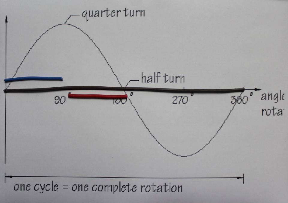
I always like to see and understand the Coil Lengths for what they are and what they are meant to do! Whats why I posted the Image some time back of the Sine Wave and the Wire Lengths:


Looking back, I could have done this better! I should have had the Brown Wire as a Half Wavelength! Still the idea was there, and the supporting Videos on Antenna Theory were a help also.

Looking at the Wire Length and the Potential, we see Potential is maximum at 1/4 or Quarter Wavelength.

We know from our Antenna Wave Theory Videos:


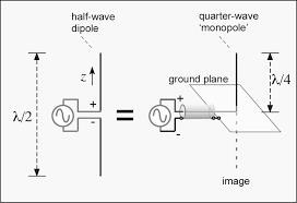
That Half Wave is normal for Dipole Antenna, and Quarter Wave Antenna must be grounded to complete the extra Quarter Wave.

Electromagnetic Waves are Important! 

I think it is important to say, remembering the short Wave, the Input Coil has only one job to do, get the Potential Up! Maximum Voltage! We need to get the Partnered Output Coils up to Maximum Voltage in the Shortest Possible Time, so this would be be at 1/4 Wavelength as seen above! Also, the best possible method to do this is via Electromagnetic Wave Theory, Resonance, Also known as Antenna Theory! 

Practically, your Partnered Output Coils Length = either Half Wave with no Grounding, or Quarter Wave with Grounding!

Your Input Coil will be 1/4 the Partnered Output Coils Wave, either half Wave or Quarter Wave. It is much easier to wind 4 to 50 turns than it is to wind several hundred at a time so Tuning the Input Coil to this wave length is much easier.

NOTE: Fighters ZPM works when Resonant, this is the same thing!

Best wishes, stay safe and well My Friend,

   Chris


Remember what Don Smith said:


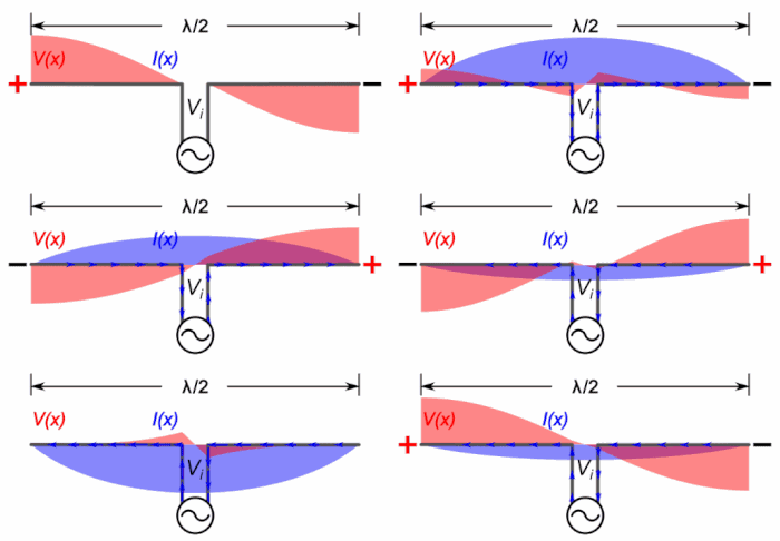
Using Antenna Wave Theory, we can see, at any one time, the ends of the Antenna has a Voltage Potential at the extreme of the scale:


Of course, we want Maximum Voltage Potential, for the minimum Input, this is at resonance, using Wave Mechanics:

Remember Floyd Sweet said the same thing:

Using a more rigorous wavemechanics approach...

Ref: Floyd Sweet Magnetic Resonance


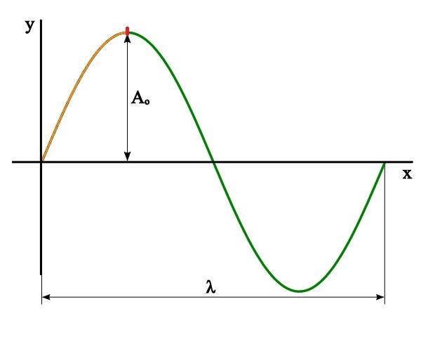
Using the Wavelength λ, and multiples of the Wavelength, λ/2 or half wavelength, λ/4 or quarter wavelength, we can Induce a Voltage on a Wire or a Coil for the least possible work!

Important: At 1/4 Wavelength, we can see we have maximum Voltage Potential!


An Antenna, Transmitting and Receiving, must have the same length and orientation!


The above video is one of the best I have seen!

Our Partnered Output Coils will always see each other as each others Source, because the lengths are the same of very close to it! They are each an Antenna, and what potential one has, the other must also have, and it will be phase locked, equal and opposite!

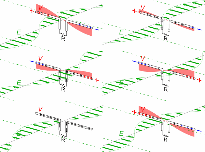
Each Partnered Output Coil works as an Antenna:


The Green Wave coming from the Other Partnered Output Coil, and the same is true on the other side of the operation! Each Coil is its partners Source!

Our Input Coil is a Harmonic of the Partnered Output Coils Fundamental, so the Input Coil is only ever the Exciter, not the Source.

It is a real shame, so many active researchers, out there on the other forums have absolutely no idea about basic physics and Science in general! It is no wonder we are Light Years ahead of the other forums!

Best wishes, stay safe and well My Friends,

   Chris

Chris posted this 22 August 2020

My Friends,

I have done a video on this some time back:


I am going to do a small experiment today and share some basic Science. Most here already know this stuff, but for those that don't, they may find this beneficial.

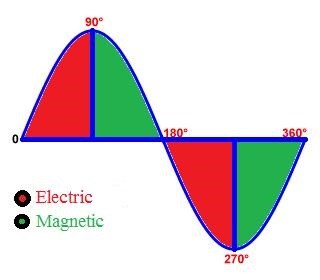
We know, and have covered many times, the above waveform has a peak Voltage Value at 1/4 and 3/4's wavelength. In other words, 90 degrees and 270 degrees is maximum Voltage Potential.

We are going to experiment today with Wire length.

I have three Coils. Two of my coils are equal, 100 Turns, each turn measuring: 176 mm in length.

At 100 turns, the Coil Length is: 17.6 meters in length.

I have another Coil, 25 Turns. Average turn length is slightly more: 179 mm in length. Total length: 4.475 meters in length.


My Friends, you will notice, and this is important, we have a situation where we need each terminal of each Coil at a Difference of Potential.

Ref: Pay attention to each Terminal - Chris, me.


What does this mean? Well, we need one terminal at Maximum Potential and one Terminal at Zero.


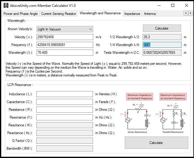
This means, we need the Full Wave Length to be equal to 4 times the Wire Length. 17.6 meters x 4 = 70.4 meters.

Mathematically:


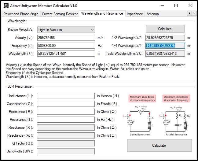
Our Resonant Frequency should be close to: 4,258,415.596 Hertz. So what do we get:

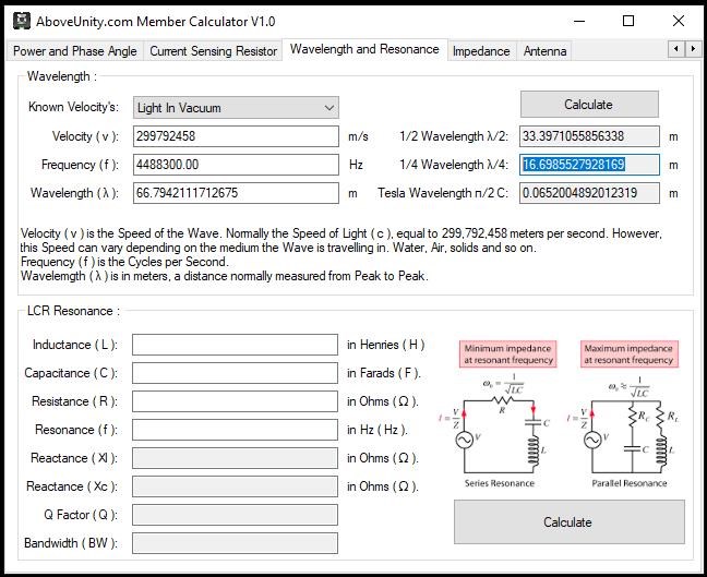
Using:


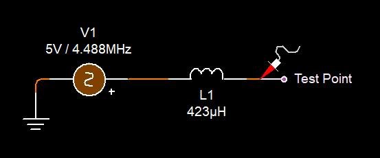
A maximum amplitude is found at: 4,488,300.00 Hertz. We have a difference of: 4,488,300.00 - 4,258,415.596 = 229,884.404 Hertz.


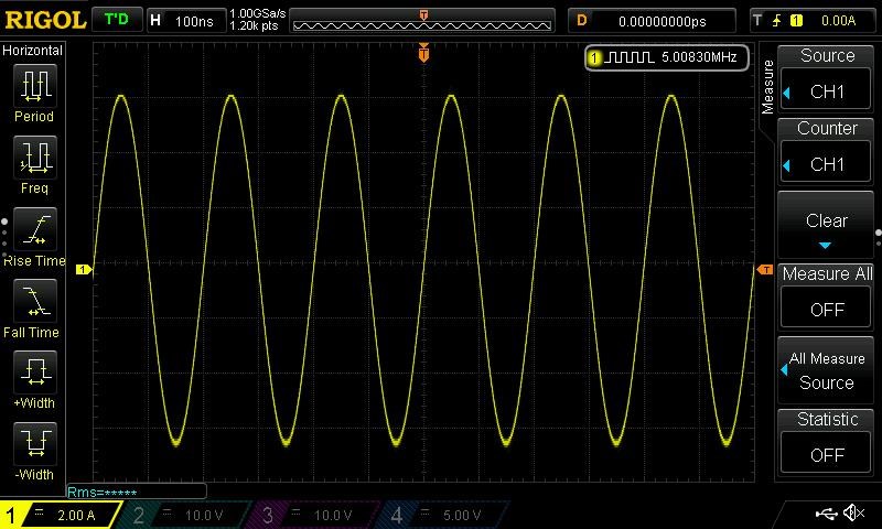
Or, using an Inductively Coupled Coil:


A maximum amplitude is found at: 5,008,300.00 Hertz. We have a difference of: 5,008,300.00 - 4,258,415.596 = 749,884.404 Hertz.


I hope we can see we have a very specific set of variables here. Just like Don Smith said, the Coil will Load and Unload at a specific Frequency!


At resonance, we have Maximum Voltage and Maximum Current for the given Wire Length. This means, the Insulated Copper Wire is able to Receive and Transmit Electromagnetic Waves at the Maximum efficiency with almost no loss. Lets not confuse what I mean about Receive and Transmit, because this is meant as a Action Reaction pair, between the two Partnered Output Coils.

Resonance is a very important aspect:


Electromagnetic Resonance is the same, Maximum Voltage, Maximum Current, Maximum Magnetic and Electric Fields. Resonance means we have maximum efficiency, the Coils do this at maximum efficiency:


Maximum efficiency Electromagnetic Induction!

I have referred to visualising the Insulated Wire, as a Wave guide. This is essentially what the Insulated Copper Wire is! A Waveguide.


Resonance is normally thought of, in components:

  • Inductance ( L ).
  • Capacitance ( C ).
  • Resistance ( R ).


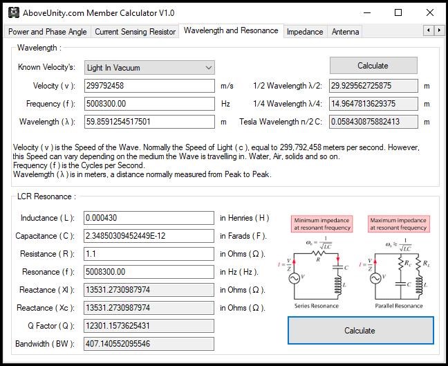
RLC Resonance is: f = 1 / 2 Pi sqrt(LC)

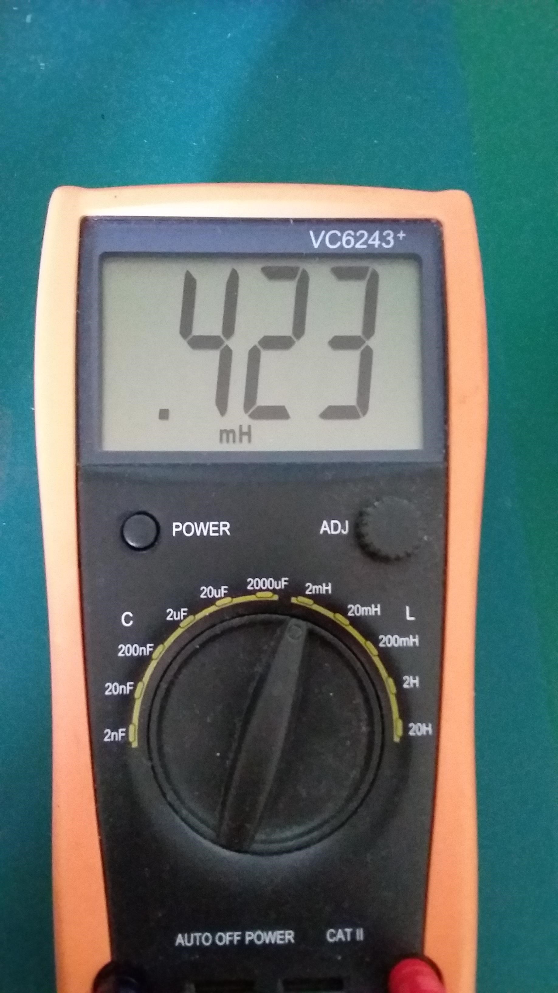
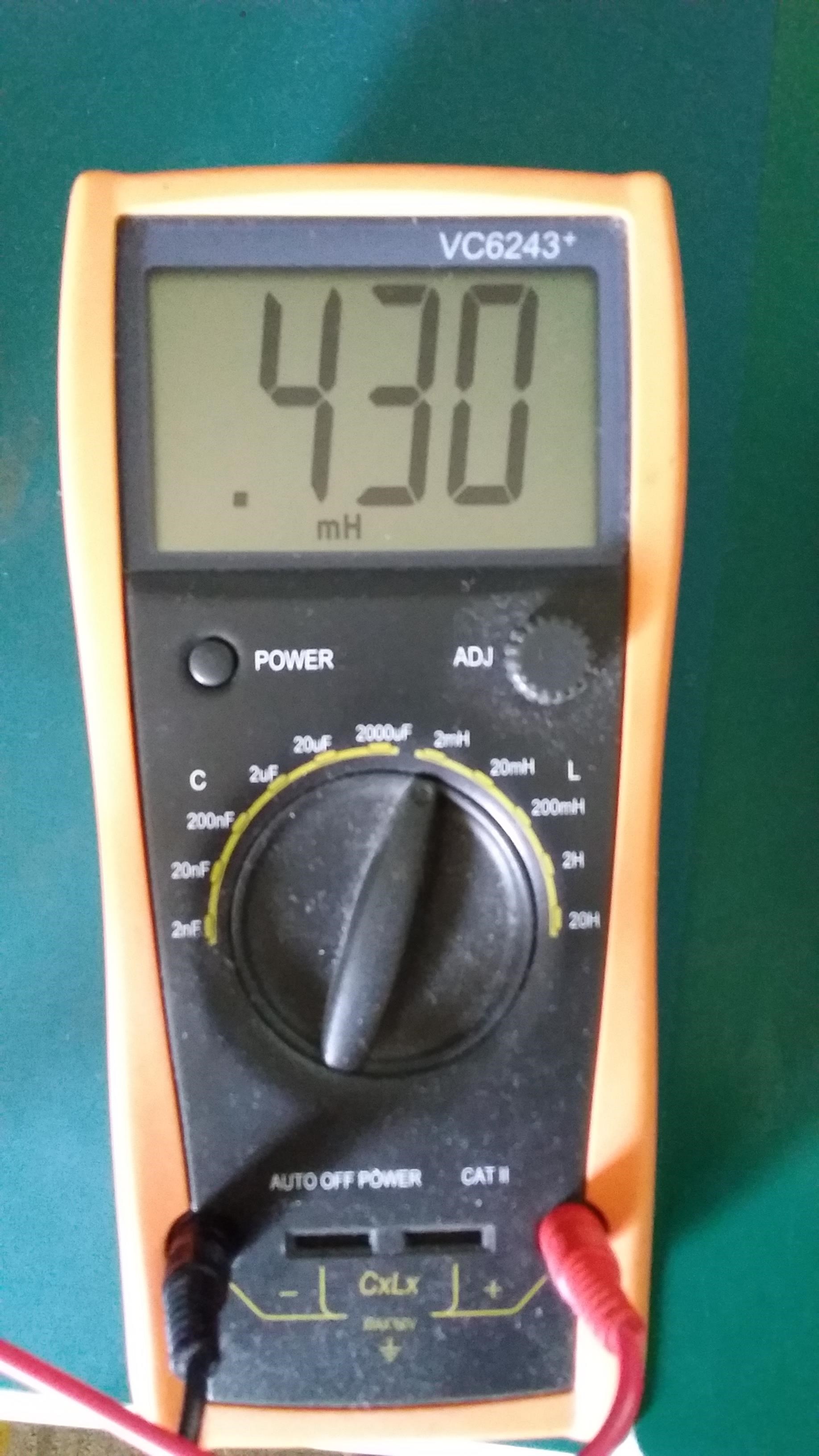
My Partnered Output Coils Inductance is:

and

Our Calculator says:

So the capacitance of the Coil is apparently: 0.00000000000234850309452449 Farads, * 106 for Microfarads, * 109 for Nanofarads, * 1012 for Picofarads. We have: 2.3485030945 Picofarads of Capacitance in the Coil.

Many here are very advanced in Electronics Engineering, so please point out errors and or better methods to approach this simple experiment!

Remember: Harmonics are our friend!  5,008,300.00 / 100,000.0 = 50.083 Hertz.

NOTE: We have seen Quarter of the Wavelength using this method:


I hope this simple experiment, finding the optimum Frequency for the Coils, is helpful to all here!

Please Note: These sorts of very simple experiments are not something you will see on the other forums! We are Light Years Ahead of the other forums!

Best wishes, stay safe and well My Friends,

   Chris

Chris posted this 05 September 2020

My Friends,

Vidura is correct!

I used an Air Core, for this very reason!

What is the Medium that allows for Electromagnetic Waves to Travel? The Aether? Or the Ether? Well, we will one day accept the Aetheric Model even if we do not today!


Aristotle noted that the motion of the body moving upward would be fire or air, and downward would be water or earth. This would mean the objects that could be effected by circular motion must be of an exalted substance. Circular motion is connected with more 'heavenly bodies' such as planets. The planets that were allowed to be in circular motion were spheres. These planets revolve around an Earth. He believed the initial motion of the objects was from a 'prime body' who acted on the outermost sphere. Since these spheres are moving in a circular motion, they could neither have weight or lightness as they cannot move naturally or unnaturally towards or away from the centre. The prime body was seen as always running and eternal, going past any other element. This element was known as aether or quintessence. Essentially, this was the fifth element which made up the Sun, planets and stars. Aether or αá¼°θήρ was described as a pure, perfect substance, which is unlike anything else on Earth.

Ref: Aristotle's On the Heavens


Look how it is coming back:

In physics, quintessence is a hypothetical form of dark energy, more precisely a scalar field, postulated as an explanation of the observation of an accelerating rate of expansion of the universe. The first example of this scenario was proposed by Ratra and Peebles.

Ref: Wikipedia


The Quintessence was discussed by the Greek, before our modern age! 

The word αá¼°θήρ (aithḗr) in Homeric Greek means "pure, fresh air" or "clear sky". In Greek mythology, it was thought to be the pure essence that the gods breathed, filling the space where they lived, analogous to the air breathed by mortals. It is also personified as a deity, Aether, the son of Erebus and Nyx in traditional Greek mythology. Aether is related to αá¼´θω "to incinerate", and intransitive "to burn, to shine" (related is the name Aithiopes (Ethiopians; see Aethiopia), meaning "people with a burnt (black) visage")

Ref: Wikipedia


It is everywhere when one chooses to look:

In Plato's Timaeus (58d) speaking about air, Plato mentions that "there is the most translucent kind which is called by the name of aether but otherwise he adopted the classical system of four elements. Aristotle, who had been Plato's student at the Akademia, agreed on this point with his former mentor, emphasizing additionally that fire has sometimes been mistaken for aether. However, in his Book On the Heavens he introduced a new "first" element to the system of the classical elements of Ionian philosophy. He noted that the four terrestrial classical elements were subject to change and naturally moved linearly. The first element however, located in the celestial regions and heavenly bodies, moved circularly and had none of the qualities the terrestrial classical elements had. It was neither hot nor cold, neither wet nor dry. With this addition the system of elements was extended to five and later commentators started referring to the new first one as the fifth and also called it aether, a word that Aristotle had not used.

Ref: Wikipedia


The medium is important, it is Everything, Everything is it!

Best wishes, stay safe and well My Friends,

   Chris

Chris posted this 08 September 2020

hi chris, nice scope-shots! question.... why can there be magnetic induction when no current flows? i guess there is no current flowing because of open circuit. maybe you trigger only the domains from the wire and because of that you can see a waveform?

some time ago i had a similar situation with an halfbridge where i connected an aircoil  and let one end open. the waveform was on the scope but there were no magnetic field present in the coil.

still so many things to learn...

regards!


Hey Baerndorfer,

My Friend, EXCELLENT Questions!

You are right, it is open circuit, no Current as we understand current can flow! However, the Coil is in Resonance. We do still have Current! As the Coils moves into the Resonant Frequency, the Current is Cycled.

Like an LC Circuit, very little Current is used, the related Q Factor, it is Cycled from Electric, stored in the Capacitor ( Distributed Capacitance or Inter Winding Capacitance ), to Magnetic, Energy is stored in the Magnetic Field:


As you know, Open Circuit means no closed Circuit, no Closed Circuit no Current can be supplied from the Source, right? Well not entirely true. There is a bit of Current. It builds up over time.


I have covered some of this stuff in a few threads, one being: Parametric Excitations of Electric Oscillations

In this circuit, we have Capacitive Coupling, even though we don't have a fully connected or closed circuit. The Capacitive Coupling can complete the Circuit to some degree and allow for some Current to flow:

Capacitive coupling is the transfer of energy within an electrical network or between distant networks by means of displacement current between circuit nodes, induced by the electric field. This coupling can have an intentional or accidental effect.

Ref: Wikipedia


With everything, I am also learning, so please check and research what I am saying, however, I am pretty confident this is how its working. I hope this makes sense?


Charged Particles inside the Coil are in Resonance! Each and every one of them all in unison!

Best wishes, stay safe and well My Friends,

   Chris

Chris posted this 12 September 2020

My Friends,

NOTE: Speculation ahead.

In Floyd Sweets VTA, I am fairly confident he used a simple Faraday's Law Equation to get his Voltage up, the task we have a bit of trouble with, but know of a few ways.

Remember what Walt Rosenthal told us:

The VTA "likes" to always see a minimum load of 25 watts.


Well, each Coil has a given Current, at 25 watts, and 120 Volts, the current is: 0.20833 Amperes.

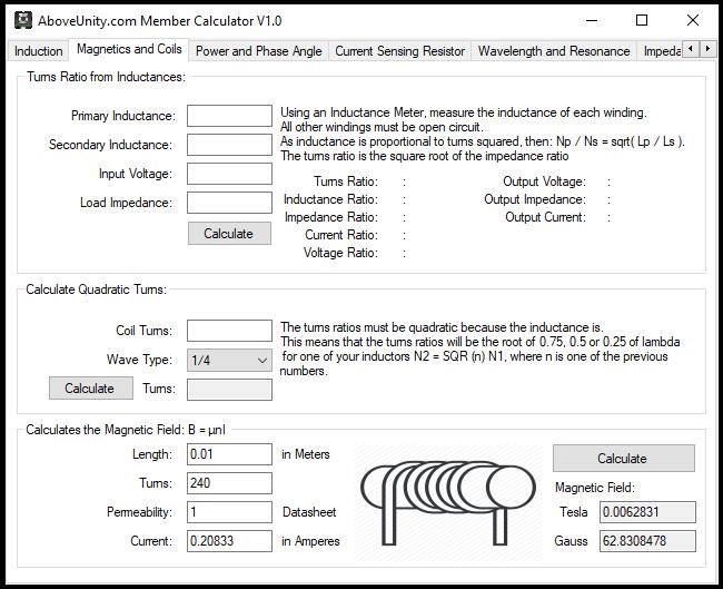
Of course, knowing the Coil Dimensions, one could calculate the Magnetic Field B: 62.8308478 Gauss.

Note: Again I am speculating some what, I am not intending to mislead anyone but want to share some basics:


Consider for a moment the construction of the triode which includes the bifilar coils located within the fields of the two conditioned magnets. 

When the current in one half of the conductors in the coils (i.e., one of the bifilar elements in each coil) of the device is moving up, both the current and the magnetic field follow the right-hand rule.


The resultant motional E-field would be vertical to both and inwardly directed.

At the same time the current in the other half of the conductors in the coils is moving down and both the current and magnetic field follow the right-hand rule.


The resulting motional E-field is again vertical to both and inwardly directed.

Thus, the resultant field intensity is double the intensity attributable to either one of the set of coil conductors taken singularly.

Expressed mathematically: E = ( B x V ) + ( -B x -V ) = 2 ( B x V )


Putting each bifilar element into each Coil, we get:


Again, a step closer to achieving Floyd Sweet level of Energy Machine, perhaps. I think it depends on how open ones mind is to the possibilities?

October 10, 1871, Patent No. 119,825, Daniel McFarland Cook was right all along, we just weren't smart enough to figure it out!

Best wishes, stay safe and well My Friends,

   Chris

Chris posted this 16 October 2020

My Friends,

The video that started me on YouTube, as corrupt as it is, Floyd Sweet Forgotten Genius:


I referenced this video, in my last video:


In this post, I want to talk about Coil Dimensions. This image shows what I mean:


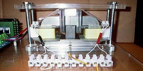
Here is the completed, Generation 6 VTA:

Above, you can see the closest rule I can find to what we saw in Floyd Sweet's image. This is in CM and not in inches, so I cant be sure its right. Do we have another method of getting some idea of the Coil Sizes?

Yes!

Taking note of Floyd Sweets knuckle length:


My Knuckle length is:


So roughly 50mm, this means, Floyd Sweets must also be very close, not exactly, but close.

Reevaluating the image again, we can confidently say, approximately two knuckle lengths wide for the Coils:


I have to say it, I have never seen Magnets 100mm x 200mm, but the length of these Magnets are in the order of 2x the width and this is seen against the Rule also. So we have to say 200 mm long.

Height, a value that has changed dramatically over the Generations of the VTA, see VTA Generations Here, is approximately one Knuckle Length, or 50mm. Its worth noting, Floyd Sweet wrote about this, as "Aspect Ratio", in his paper: "Nothing is Something

We now have dimensions of the Coils in Generation Six VTA, 100mm x 100mm x 50mm, here is what we have learned:


Floyd Sweet said:

Now let us consider the losses. Copper or Cu I2R losses remain but may be minimized by using wire of larger than usual cross-sectional area.

...

As the load current increases, the complimentary flux adds to the cross flux. The voltage output remains constant. The primary limiting factor is the cross sectional area of the phase winding conductor.

Ref: The Space-Flux Coupled Alternator by Floyd A Sweet


Now, we have a problem, and something that is hard to prove for sure, we know each Power Coil had 2 Wires, or were Bifilar. There is some evidence to show Floyd Sweet wound his Coils one on top of the other, this is both written form and also pictorial form:


If one studies the above image, one can see an uneven edge horizontally through the middle. This also supports what Floyd Sweet said: "The resultant motional E-field would be vertical to both and inwardly directed" He said this for both Coils and gave Arrows to show this also:


This means, we have Two separate Coils, within our known dimensions, 100mm x 100mm x 50mm, that fit 100mm x 100mm x 25mm each, one on top of the other.

We have come far in a short time!

We also know, 240 turns of 0.8mm wire was used in most of Floyd Sweets Machines!

I wish to point out, Walt Rosenthal also said, importantly:

The VTA "likes" to always see a minimum load of 25 watts.


As pointed out previously, each Coil has a given Current, at 25 watts, and 120 Volts, the current is: 0.20833 Amperes. Here.

Furthering on this post some, we can calculate the Field in Gauss: 


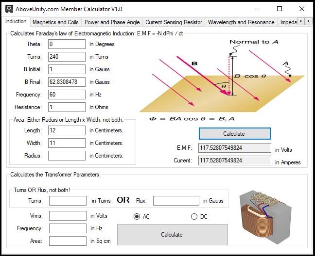
You can see, for the Dimensions we have, we need a Change of Flux of: 1 to 85 Gauss at 60Hz to generate a Voltage of 120.96 Volts.

Remember: Your Input Coil controls the Frequency and Amplitude, not the Energy Transformation! Your Input Coil does not supply the Energy to the Machine, the Machine is an Oscillator and Energy comes directly from Encouraged Electromagnetic Induction.

Electromagnetic Induction, this is the key and essential principle, the same as every Electric "Generator"!

Best wishes, stay safe and well My Friends,

   Chris

Chris posted this 19 October 2020

My Friends,

Another video, I think it is better in a Video than a lengthy Post:


Apologies, a Codec Problem, and the video was corrupted at the end, loosing some good information. Sorry all, 3rd time lucky?


To Power a Load, we must have: Voltage first, then a Current can only flow, through the Resistance, when we put the Volume of Electrons under a pressure and then pump them!

Don't forget, the Action of Force and Reaction always count:


Force and Balance of the Forces.

Best wishes, stay safe and well My Friends,

   Chris

Chris posted this 14 January 2022

My Friends,

I want to encourage more thought on this subject! Lets use Diakoptics to move toward a better understanding!


Partnered Output Coil One

We all know, by now, any Coil that is Loaded, will have an associated Magnetic Field. Using this Circuit we Visualise Partnered Output Coil One:

This Magnetic Field can be calculated using Amperes Law:


So, at Peak Magnetic Field, with a Coil using the following Design Characteristics:

  • Length = 25mm
  • Turns 240
  • Permeability = 200
  • Current = 0.20833 Amperes.


We get a Magnetic Field = 5026.467821 Gauss!

All this, simply because we have a Current Flowing in the Wire!


Partnered Output Coil Two

Again, we all know, any Coil that is Loaded, will have an associated Magnetic Field. Using this Circuit we Visualise Partnered Output Coil Two:


Because we have a Changing Magnetic Field in Partnered Output Coil One, and we know what this Magnetic Field is: 5026.467821 Gauss, then we can use this same Magnetic Field, as it Changes in Time, to "Generate" a Voltage in Partnered Output Coil Two!

Using Faradays Law of Electromagnetic induction, we can Calculate this Voltage:


You can see, 126 Volts using a Coil with the same Turns, and the displayed characteristics!


Combined Interactions

We have an Electric "Generator". With Changing Magnetic Field in close proximity, we get this occur:


Using clever design, pointed out here: Coil Geometry we can very easily get a grasp of why we get this:


Partnered Output Coils Oppose each other, exactly as the Stator and Rotor do in an Electric "Generator". The difference is, we are Solid State and we use an Input Coil to Excite, or give the impression of Delta t, the Time Rate of Change.

Best Wishes,

   Chris

Chris posted this 03 August 2022

My Friends,

Partnered Output Coils are Symbiotic like Tuning Forks:


Ring one, and the other starts to go also, the exact same way! To do this, Partnered Output Coils must be loaded to work, because a Load defines the Current which in turn defines the Magnetic Field!

This is the Symbionce of the Coils in Magnetic Resonance! You could almost say a Sympathetic Resonance:


Do you remember this video:


In the VTA Gen 1:


We saw a Bridge Rectifier, on the Input, do you know why Floyd Sweet had this in place?

The Rectifier turns AC Input from the top waveform to the bottom waveform:


Take note of the shape of the Rectified Pulses! Dont forget, half Bridge Rectification is also possible. 

Best Wishes

   Chris

Chris posted this 04 March 2023

My Friends,

Never before, ever, has this happened:

 Start Here → Builders Guide to Aboveunity Machines

There are two mistakes along the way to MasteryNot Starting and and not going all the way!

Cite: Master Shi Heng Yi

On rare occasions, Sweet saw this effect, called self-oscillation, occur in electric transformers

Ref: http://merlib.org/node/5282

The Answers you seek are right here:


I have provided 11 videos on this showing you how to approach this Technology! I have given you all of the data to make this work, and more, to make this, not just a TOY, to make this Power very much more than just a few Globes!

My Friends, when I see 10 successful replications, I will release another Video showing a bit more work, again we have had quite a few successful replications already! Do the Math in these videos! COP > 1.6 in both Machines!

Tinman was the first:


Others followed, like Captainloz:


Others also, some may not want their names used? Security for people is important to me, but eventually, we must do this as a Team and make a Stand!


Some have taken advantage of this, some plunder it.

Its so simple, and so cheap! The problem is, too many stupid, stupid people in the community!


Don't tell anyone, but

We are LIGHT YEARS Ahead of the other Forums!


Best Wishes,

   Chris

Chris posted this 11 August 2017

I would like to point out a very interesting fact. Floyd Sweet said: "No Vibrations" @17:01 in the below video:


For your convenience, the initial release of this video is below for comparison:


Also, another important thing is, we know from images and the above video, that Floyd Sweet had problems with Vibrations:

  
Check out that huge sponge!

When the Coils Oppose, of course as you can imagine, they throw out a lot of Vibration! I guess, like a Bucking Bronco, trying the best he can to Buck Off the Rider, the Magnetic Fields under high Stress, want to separate!

 Its a hard one truth, but the early Floyd Sweet work is just too easy to pass by, but, when replicated, and replicated properly, this works:


In my opinion, its the smallest things that lead to the greatest successes. This work is the same as The MEG, only used in a slightly different way.


Don't forget the Magnets! Floyd Sweet gave us the reason to use Magnets:

An approximate analogy, not by any means perfect, is as follows:


Picture a side-wheel paddle steam boat making its way down stream in the same direction as a fairly strong tidal flow. Assume the steam engine to be highly efficient, say 80%. Now assume the engine to be working at this efficiency and that the tidal energy integrates with that of the engine in propelling the ship. The acceleration increases to a point where the horsepower increases beyond that equivalent energy consumed by the engine. If one were not aware of the tidal flow energy integrated with that of the consumed energy, one would conclude the engine efficiency was greater than unity. This is hypothetical. As the momentum of the tide relates only to the mass of the steamboat’s displacement of the medium, water. Actually if the forward momentum of the tide was able to relate only to the paddle wheel the forward or positive force would tend to force the wheel to turn in the opposite or negative direction.


Then in the hypothetical case, the force of the tide on the mass of the ship would equal the force acting on the paddle wheel and the ship would be motionless. In order to move in the forward direction, the engine would need to overcome the negative force of the tide on the wheel. Little engine hp would be needed, as it would integrate with the positive flow of the tide, acting on the displacement mass of the ship. The above is not achievable in practice, as the only way the tide could relate to the paddle wheel in such a manner, the mass of the ship would have to be completely out of the water and only the wheel within the flow of the tide would turn, as the momentum of the flow of the tide would not be in effect. This is reactive power – no work is done. The wheel turns but the ship is motionless. Conversely, if this were a possibility, then a ship moving against a strong tide, would be able to traverse a river without either engine of sail, by means of the force of a moving mass of water against the wheel paddles. As stated, the force of the mass of water flowing against the displacement mass of the ship predominantly opposes the positive motion of the ship. The analogy though far from perfect, suggests that if one were not aware of the visible force acting on the movement of the ship, at times, assuming all parameters were measurable, the indication might be that the engine was capable of greater than unity efficiency.

When read enough times, you can see that in a certain System, the Magnetic Field from the Magnets gets integrated, added to the System, with the System's operation! Because it is moving in Time, it is now an Electric Field, this we know already, it is the Magnetic A Vector Potential.

I pointed out some work I did in the Resonance Thread:

Some years back: 29.11.2015 I did an experiment. It was very interesting. The layout:

Very simple, but also very effective. With no Earth lead I could not make this work, with an Earth lead, I found a resonance at a very unusual frequency! in my setup I found at around 1208Hz, my Input went nearly to Zero.

Yet the device was shaking as if it had a few dozen watts through it.

Input Voltage becomes nearly Sawtooth, Triangle Wave - but is in-fact Square, H-Bridge Switched DC

I have a sensing Coil on one leg - Voltage on the Coil goes up showing higher Voltage at resonance as one would expect

An example of Resonance. I had posted this to the net, none were interested!

   Chris

   Chris


Fighter posted this 13 May 2019

I found this, I think it belongs to this thread.

He is using AMCC core meaning that is a Metglas core with special characteristics, not sure if this works the same with ferrite cores.

What I found interesting is the guy is saying when using pulsed DC there is no over-unity but when using real AC there is over-unity.

Zanzal posted this 13 May 2019

Hey Fighter,

What I found interesting is the guy is saying when using pulsed DC there is not over-unity but when using real AC there is over-unity.

I do think there is something interesting about amorphous alloy cores. I noticed a strange behavior with square waves when using these cores. A square wave on the input primary, often results in a square wave on the output secondary. This was common to observe, but not observed in every circuit. This seemed a little strange when I first saw it, because I have never seen this in non-amorphous cores it was a little puzzling. I didn't pay much attention too it, but I read a comment in Patrick Kelly's book that I thought was interesting, suggesting these cores have enough bandwidth to pass multiple frequencies. As the square wave can be thought of as a summation of multiple sine waves at different frequencies and amplitudes this made some sense to me. I've put no time into researching it, but it might be a relevant to support investigating the claim above.

Chris posted this 07 August 2020
Hey CD,

I agree, I also have the feeling that EPR is involved.

Ruslan, a legend, gave us this golden information:


In my effort to learn more about how this tech works, I have always been open to others ideas and methods. Ruslan's exquisite Radio Engineering background gives him a very good path on Antenna Theory, a theory as you know, I have also been very sportive of in the basic understanding of this technology!

I quote Ruslan:

I'll tell you there myself a little on this coil, one more time yes. Here inductor is an inductor pro wire length of all this brown from end to end, these with these including yes it is 37 and a half meters.

We are now opening a calculator, for those who is here, but I think there is someone we are have already dropped this very calculations, and then there is inductance so so so so you now here we will open oscillatory circuit advanced calculation, and now I will show you means you could not see because you can see so well.

That's the frequency yes that is enter and purity period wavelength, wavelength and quarter wavelength, length wave.

Our wavelength is equal to the length waves, me wires means that we make a wire with us 37 s half here you go means a quarter length how many waves we get 8 megahertz, got got me ?

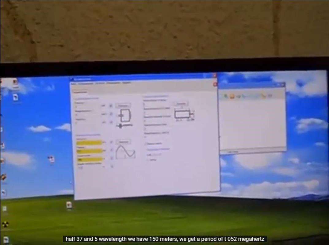
So quarrel moment wavelength quarter quarter waves are shorter so we have a quarter of a wave it turns out 37 and a half 375 length waves, we have 150 meters, we get a period t 052 megahertz.

Yes this picture means that's what you have to mean that's what we have it turns out yes that is, this is a coil with us this particular weight coil so this coil we have two megahertz yes, that is, this is its resonant frequency wave until you cadet quarter-wave me somehow that a quarter of a rum the so-called antenna what if 37 and 5 take this from us the length of the whole wire which is the inductor we have must also be a multiple, we take 37.5 divide by 2 by one second we get 1875 here the coil should be in this place to be reeled in 1875 no other.

I proceed from calculations the coil itself, but again, so that this start winding the coil naturally to us will need a conversation about how we will have high voltage tesla.

Tesla as such she's here on this side and unwound now I will rewind here it is necessary to wind such a tesla that will give two megahertz but 2 megahertz she should give us on the antenna here that's where the antenna will be very necessarily antenna two fingers between here these inductor and antennas must be required i.e. capacitive coupling antennas around this all there should be something the less the better the antenna will irradiate already this high-frequency high-voltage field is already the whole thing without inductive inductive coupling the less the better but again I say not overdo it well, about one and a half two finger like this should be yes that is about winding top antennas what we do we we absorb energy from the environment into this place where will she converge with the energy that is already here will be in inductors here will be the current load before that is, the flow will be what do you do you just connect only voltage voltage will be from Tesla it will be from Wednesday make tesla.


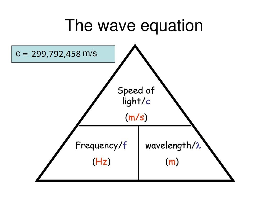
Remember our Wave Equations:


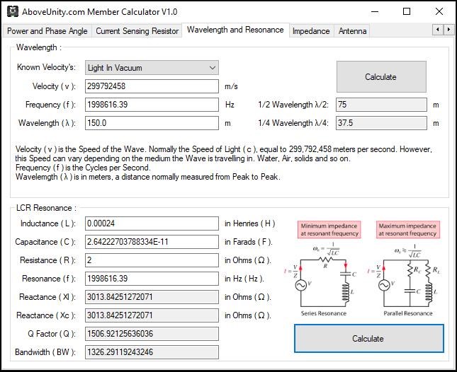
299,792,458 m/s / 37.5 meters = 7.99446555 MHz x 0.25 = 1.9986163875, close to 1.875 MHz! Damping could be the difference!

Why 1/4 Wavelength? Its still not clear?

Turn for Turn, lets work it out:

  • 2 Layers Counter Clockwise.
  • 1/2 Layer Clockwise.
  • 1/2 Layer Clockwise.
  • 1/4 Layer Clockwise.
  • 1/4 Layer Clockwise.


In decimal, 2.0 + -0.5 + -0.5 + -0.25 + -0.25 = 0.5. 1.5 - 2.0 = 0.75. 1.0 - 0.75 = 0.25 or 1/4 of the total turns in the Coil are Inductive, Three Quarters of the Coil is non-inductive.

Is this the reason for the 1/4 Wave length? I don't know! I do know Resonance in a Half Wave Antenna, requires Lambda / 2, a Quarter Wave Antenna is Lambda / 4 or Quarter Wavelength:


Perhaps YoElMiCrO can provide a little more insight on this topic? My knowledge is limited in these areas, I have tried to learn as much as I can, but still have a lot to learn!

Best wishes, stay safe and well My Friends,

   Chris

Chris posted this 10 August 2020

My Friends,

I want to go into a little more about Ruslan's Wave Theory.

Ruslan said:

That's why Roman (Shark) says that he is eating ground ... Everything is right! Because it kills the half-period pulse at the reception, which is grounded.

This can be seen in all his settings! I wondered for a long time why he decided to use this solution and realized that it's easier to pick up BB diodes. Since interference at such frequencies in Tesla will lead to its improper operation.

In other words, it will not be possible to cut off the half-period. Kapa solved this issue with an arrester and rectifiers at low frequencies.

There everything is simpler, but more wires ....

So on the German installation the diode is small, Tesla is far away, the grounding cable is long. By the way is equal to the length of Tesla !!!

Do not forget about grounding .... On this installation it is important and without good support (grounding) will not work. Do not forget that the systems use high voltage. As we know, it moves even in the air. That's why grounding is necessary. Plus wave resonance and safety .... Like that .....

Ref: Ruslan K


This is a really important statement! Lets look at this again:

Tesla is far away, the grounding cable is long. By the way is equal to the length of Tesla !!!


So, if we look at the above, where Ruslan says the Tesla is 37.5 Meters, then the Grounding Cable must also be 37.5 Meters!

Now, we must look at this as a Dipole antenna, or a Monopole antenna, where 1/4 wavelength is 37.5 Meters, half wave is 37.5 x 2 = 75, and thus full Wave is 150 Meters! This is what Ruslan says, but it is not clear, in the following video:


The Image here:


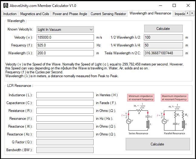
Now, I have to say, some of this, I do not understand, I have struggled with this for a long time! I have learnt Antenna Research from scratch and still have a lot to learn! The Above Unity Member Calculator provides some useful calculations to assist us with these calculations:


What evidence for a long Grounding Cable do we have? A Lot!


It is worth noting, Nikola Tesla also had patented this very requirement in Patent No#: US787412A

The ground should be made with great care, with the object of reducing its resistance. Instead of being directly grounded, as indicated, the coil C may be joined .in series or otherwise to the primary A, in which case the latter will be connected to the plate E; but be it that none or a part or all of the primary or exciting turns are included in the coil C the total length of the conductor from the ground-plate E to the elevated terminal E should be equal to one-quarter of the wave length of the electrical disturbance in the system E C E or else equal to that length multiplied by an odd number. This relation being observed, the terminal E will be made to coincide with the points of maximum pressure in the secondary or excited circuit, and the greatest flow'of electricity will take place in the same. In order to magnify the electrical movement in the secondary as much as possible, it is essential that its inductive connection with the primary A should not be very intimate, as in ordinary transformers, but loose, so as to permit free oscillation that is to say, their mutual induction should be The spiral form of coil (J secures this advantage, while the turns near the-primary A are subjected to a strong inductive action and develop a high initial electromotive force. 

Ref: Patent No# US787412A


The best and most convenient manner of carrying out the invention of which I am now aware, is to surround the freely vibrating circuit or conductor, which is to be maintained at a low temperature, with a suitable cooling medium, which may be any kind of freezing mixture or agent, such as liquid air, and in order to derive the fullest benefit from the improvement, the circuit should be primarily constructed so as to have the greatest possible self-induction and the smallest practicable resistance, and other rules of construction, which are now recognized, should be observed. For example, when, in a system of transmission of energy for any purpose through the natural media, the transmitting and receiving conductors are connected to earth and to an insulated terminal respectively, the lengths of these conductors should be one quarter of the wave length of the disturbance propagated through them.

Ref: Patent No# 13,563


The length of the thin wire coil in each transformer should be approximately one-quarter of the wave length of the electric disturbance in the circuit, this estimate being based on the velocity of propagation of the disturbance through the coil itself and the circuit with which it is designed to be used. By way of illustration, if the rate at which the current traverses the circuit including the coil be one hundred and eighty-five thousand miles per second then a frequency of nine hundred and twenty-five per second would maintain nine hundred and twenty-five stationary waves in a circuit one hundred and eighty-five thousand miles long and each wave would be two hundred miles in length.

Ref: Patent No# 649,621


So far, I am happy that this explains the question I posed in the last post:

Is this the reason for the 1/4 Wave length?


1/4 or Quarter Wavelength is used because 37.5 Meters is 1/4 of 150 meters.

NOTE: 1/4 Wavelength is maximum Potential for the shortest Time.

Best wishes, stay safe and well My Friends,

   Chris

Jagau posted this 12 August 2020

 HI Aloha


Chris has already covered this topic here  
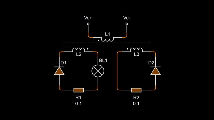
http://www.aboveunity.com/thread/timing/

about common mode and differential mode


Jagau


Chris posted this 16 August 2020

Thank You Aloha!

Best wishes, stay safe and well My Friend,

   Chris

Fighter posted this 17 August 2020

I translated it, anyone can download it from here.

Don't expect the translation to be 100% accurate because I used automated translation and I can't verify it,

I don't speak Russian.

But it's accurate enough to give details about what's happening on that Russian forum.

Thank you Aloha !

Chris posted this 17 August 2020

My Friends,

@Fighter, Thank You!

I want to spur more thinking on the Technology:

Turn for Turn, lets work it out:

  • 2 Layers Counter Clockwise.
  • 1/2 Layer Clockwise.
  • 1/2 Layer Clockwise.
  • 1/4 Layer Clockwise.
  • 1/4 Layer Clockwise.


In decimal, 2.0 + -0.5 + -0.5 + -0.25 + -0.25 = 0.5. 1.5 - 2.0 = 0.75. 1.0 - 0.75 = 0.25 or 1/4 of the total turns in the Coil are Inductive, Three Quarters of the Coil is non-inductive.


In the Grenade Coil:


We need to think of each turn and its respective Direction, as a Separate Coil! What do I mean? I mean the singular Grenade Coil as two Coils, one Clockwise ( 75% Turns ) and one Counter Clockwise ( 25% Turns ) in this case.

Two separate Coils, Fields Opposing, we get something similar to this:


Using Electromagnetic Wave Theory, as Nikola Tesla described, we can find the resonance of the Coils, and then, thus, draw Amplified Current and Voltage, greater than Unity or Above Unity Power Output!

 the circuit should be primarily constructed so as to have the greatest possible self-induction and the smallest practicable resistance, and other rules of construction, which are now recognized, should be observed. For example, when, in a system of transmission of energy for any purpose through the natural media, the transmitting and receiving conductors are connected to earth and to an insulated terminal respectively, the lengths of these conductors should be one quarter of the wave length of the disturbance propagated through them.

Ref: Patent No# 13,563


There are many ways to bring the Coils into Resonance, as pointed out above, a mosfet driven Push Pull Driver and a Spark Gap via a very low resistance Coil is one that Kapanadze used, as he stated:

Of course, the Grenade Coil is not drawn in the above Circuit. If the Grenade coil is 37.5 meters long, and the wave resonance is 1.875MHz, then the 375 Harmonic will be 50Hz. In Ruslan's case: 1820 / 50 = 36.4 KHz, the 50th Harmonic = 36.4KHz.


On the Inductor we feed the signal of rectangles with a frequency of 1/50. Consider: 1820: 50 = 36.4 kHz pumping a rectangle through the junction (Pot) with 23-29 turns of wire 2.5 squares. I repeat, you need to make the voltage on this harmonic not 10-20 volts, but higher by an order of magnitude. Approximately up to 50-60 volts and get the same dancing effect at the output.


double GrenadeResonance = 1875.0; // 1820.0

for (int i = 2; i < 501; i++)
{
    Console.WriteLine(GrenadeResonance + " / " + i + " = " + (GrenadeResonance / Convert.ToDouble(i)));
}


Remember: Grenade Resonance is where the Fields are 180 Degrees out of phase and the Magnitude, even though the Turns are not the same, are equal. This means external Magnetic Fields are not going to be negatively affected, because we have a Positive and a Negative force exerted on the Wire, 1 + -1 = 0, so no net negative affect on the Input!

Key Concept: Increasing the Voltage, because Current I = Voltage V / Resistance R.

So much work, so little time.

Best wishes, stay safe and well My Friends,

   Chris

Chris posted this 19 August 2020

My Friends,

I believe the following two videos are the most important Ruslan has ever done:


you need to get this effect, and this you understand that there is an hour, if you twist more precisely, turn this sinusoid here it is, she, but she doesn't dance here like that then it doesn't seem to be visible it is necessary to reduce it from me a beach is generally a beach it seems that sine clean nifiga not clean here they are there she is standing wave will it work for me how the purity increased and I understand like this, behold!


The Standing Wave is KEY to this technology:

Magnetic Resonance, Clock Wise and Counter Clock Wise turns, in what we call Non Inductive mode, but in point of fact is highly inductive, as Tesla pointed out:

the circuit should be primarily constructed so as to have the greatest possible self-induction and the smallest practicable resistance, and other rules of construction, which are now recognized, should be observed. For example, when, in a system of transmission of energy for any purpose through the natural media, the transmitting and receiving conductors are connected to earth and to an insulated terminal respectively, the lengths of these conductors should be one quarter of the wave length of the disturbance propagated through them.

Ref: Patent No# 13,563


Best wishes, stay safe and well My Friends,

   Chris

Chris posted this 19 August 2020

My Friends,

A little thinking out loud in this post:

I have tried, since the early days, link Antenna Theory, to the machines we are all working on.

The length of a dipole is the main consideration for determining its operating frequency, and as a result, calculating the length is a key element of designing and installing any dipole antenna whether for HF, VHF, or UHF, etc..

Ref: Dipole Antenna Length: calculation & formula


Many of the greats before us have said that the machines are directly, 1/4 Wave or 1/2 Wave machines in their operation!


Ruslan wrote about Wave Mechanics:

The first rule: Wind the coil 40 meters. 2. Find out its resonant frequency (1/4 wave) Inductor 1/4 = 10 meters of the same wire (for example, 2.5mm) Connect the generator to a 10 meter coil, drive the rectangles at a frequency of 1 MHz and crawl higher until 40 meters do not appear sinusoid. The maximum amplitude. The generator is desirable to take a normal, laboratory! With output adjustment from 0 to 20 volts. We achieve maximum amplitude and move tenths of a kilohertz until it starts to dance. This is your wave resonance !!! We fix the frequency and voltage.


Also in his video:


Floyd Sweet wrote:

Resonance frequencies may be maintained quite constant at high power levels so long as the load remains constant. We are all familiar with AM and FM propagation, where in the case as AM, the voltage amplitude varies, and with FM, the frequency is modulated. 

However, the output power sees a constant load impedance, that of the matched antenna system. If this changes, the input to the antenna is mismatched, and standing waves are generated resulting in a loss of power. The frequency is a forced response and remains constant. Power is lost and efficiency becomes less and less, depending on the degree of mismatch.

Ref: Magnetic Resonance by Floyd A. Sweet. Ph.D.


This is just a small snippet, a few quotes of many! We must be wise and pay attention here!


Let take Don Smith's machine as an example:


What do we have:

  1. Primary, 4 Turns.
  2. Secondary, 16 Turns.
  3. Secondary, 16 Turns.


Mathematically:

4 / 16 = 0.25 or 1 / 4 or one Quarter.

I have estimated each turn' length to be 200 mm.

16 x 200 = 3.2 meters.

3.2 meters Wavelength is: 93685143.125 Hz

Now, 4 turns approximately 200 mm each is 0.8 meters.

0.8 meters Wavelength is: 374740572.5 Hz

93685143.125 / 374740572.5 = 0.25 or one Quarter!

You will note:

The first rule: Wind the coil 40 meters. 2. Find out its resonant frequency (1/4 wave) Inductor 1/4 = 10 meters of the same wire (for example, 2.5mm) Connect the generator to a 10 meter coil, drive the rectangles at a frequency of 1 MHz and crawl higher until 40 meters do not appear sinusoid.

Ref: Ruslan also said the same thing!


Ok, we see a pattern here, its quickly making some sense! Well sort of anyway...

Again, going through Nikola Tesla's Patents and reading about the Quarter Wavelength relationships gives great insight! I have provided some above, not all but the best ones I could find quickly. I post them again below:


The ground should be made with great care, with the object of reducing its resistance. Instead of being directly grounded, as indicated, the coil C may be joined .in series or otherwise to the primary A, in which case the latter will be connected to the plate E; but be it that none or a part or all of the primary or exciting turns are included in the coil C the total length of the conductor from the ground-plate E to the elevated terminal E should be equal to one-quarter of the wave length of the electrical disturbance in the system E C E or else equal to that length multiplied by an odd number. This relation being observed, the terminal E will be made to coincide with the points of maximum pressure in the secondary or excited circuit, and the greatest flow'of electricity will take place in the same. In order to magnify the electrical movement in the secondary as much as possible, it is essential that its inductive connection with the primary A should not be very intimate, as in ordinary transformers, but loose, so as to permit free oscillation that is to say, their mutual induction should be The spiral form of coil (J secures this advantage, while the turns near the-primary A are subjected to a strong inductive action and develop a high initial electromotive force. 

Ref: Patent No# US787412A


The best and most convenient manner of carrying out the invention of which I am now aware, is to surround the freely vibrating circuit or conductor, which is to be maintained at a low temperature, with a suitable cooling medium, which may be any kind of freezing mixture or agent, such as liquid air, and in order to derive the fullest benefit from the improvement, the circuit should be primarily constructed so as to have the greatest possible self-induction and the smallest practicable resistance, and other rules of construction, which are now recognized, should be observed. For example, when, in a system of transmission of energy for any purpose through the natural media, the transmitting and receiving conductors are connected to earth and to an insulated terminal respectively, the lengths of these conductors should be one quarter of the wave length of the disturbance propagated through them.

Ref: Patent No# 13,563


The length of the thin wire coil in each transformer should be approximately one-quarter of the wave length of the electric disturbance in the circuit, this estimate being based on the velocity of propagation of the disturbance through the coil itself and the circuit with which it is designed to be used. By way of illustration, if the rate at which the current traverses the circuit including the coil be one hundred and eighty-five thousand miles per second then a frequency of nine hundred and twenty-five per second would maintain nine hundred and twenty-five stationary waves in a circuit one hundred and eighty-five thousand miles long and each wave would be two hundred miles in length.

Ref: Patent No# 649,621


I hope this data is useful for all here!

Best wishes, stay safe and well My Friends,

   Chris

Jagau posted this 21 August 2020

Thanks Chris for sharing this 1961 MIT video
I really like, we can see the notion of standing wave with 2 transmitters in constructive or destructive mode, very interesting.

We can notice that the polarization of the antenna is very important.


Jagau

Chris posted this 22 August 2020

Hey CD,

These very simple experiments, and working out the parameters involved are so extremely beneficial! We can learn so much from these experiments!

The Damping Factor, Zeta ( ζ ), plays a role in the Resonant Frequency. Here is the definition of Zeta:

Damping is an influence within or upon an oscillatory system that has the effect of reducing, restricting or preventing its oscillations. In physical systems, damping is produced by processes that dissipate the energy stored in the oscillation.


Yes, I had no Core in these experiments.

Listening to, and working toward that understanding that those before us gave, I think is super important to make steps forward. We have to try harder to understand why this line of research was so important and talked about by nearly all before us! Don Smith gave us all! We only need understand it! 


This video is the best I have ever seen, it is very beneficial:


We have to focus on the Terminals of the Coil and getting the Voltage up on these Terminals, then the Current will follow.


We already have the configuration, we only need find the resonance. Most of us already have the Resonance, in other words running machines.

Fighter has already done this, he already understands the importance of Resonance!

Best wishes, stay safe and well My Friend,

   Chris

Chris posted this 04 September 2020

Hey Guys,

Great comments, Thank You!

In an Electromagnetic Wave the Electric Field has a Plane as the Magnetic Field has a Plane, 90 Degrees to each other.


The Electric Field in Green, marked with an E:


Is the active plane, making Change in the Coils.The Magnetic Field, are effectively not touching each other, they are opposing:


This means, the Magnetic Field themselves are not responsible for the change in Current Flow as we expect in Electromagnetic Induction. Now I do not wish to confuse people, but there is a massive hole in EM Theory!

The Actual Standing Wave is the Current, or Electric Field, marked in Green:


Each Magnetic Vector sums to Zero, this is not a Standing Wave, it is no wave at all, because it is Zero. H, the Magnetic Strength, Sums to Zero, and C, the Speed of light Sums to Zero. The Green Current Arrows are Additive and they Sum, giving rise to greater Current, see The Mr Preva Experiment for this verification.

Best wishes, stay safe and well My Friends,

   Chris

Vidura posted this 05 September 2020

Great discussion! If I may add my two cent's. The basic condition for a standing wave are two signals traveling in oposite directions thru a medium. The signal pair can be of various types: mecanical, magnetic or electric. In the case of a transformer or coil arrangement the standing wave is developed in the core or the medium, not in one or another coil. altough it is possible to set up a standing wave in a conductor as well , provided that two signals travvel in oposing directions.

Vidura

Chris posted this 06 September 2020

My Friends,

In the video I recently published, here:


I have confirmed, exactly what Don Smith Told us:


Also, I have shown that using a very slightly different frequency, we can produce a Sawtooth Waveform, the required Waveform for Energy "Generation":


I hope all Members here can see the Importance of my video above! Magnetic Resonance is a very important fundamental concept, and the Concepts at Resonance show how easily the Coils can be made to Load and Unload at Specific Frequencies. It's important and we need to start thinking about this in our builds!

At Resonance maximum Voltage Amplitude is achieved! Current I = Voltage V / Resistance R

In The Mr Preva Experiment, we learned of Resonance and its importance!

Best wishes, stay safe and well My Friends,

   Chris

baerndorfer posted this 08 September 2020

hi chris, nice scope-shots! question.... why can there be magnetic induction when no current flows? i guess there is no current flowing because of open circuit. maybe you trigger only the domains from the wire and because of that you can see a waveform?

some time ago i had a similar situation with an halfbridge where i connected an aircoil  and let one end open. the waveform was on the scope but there were no magnetic field present in the coil.

still so many things to learn...

regards!

Wistiti posted this 09 September 2020

Hi Chris and freinds! Your usage of opend end coil remind me an experiment done by Skywatcher (OriginalSkywatcher here) in the thread "Bucking coil inverter " at energetic forum. He basically used his original joule thief set-up (the one I usually use in my experiment) and extract power from open end POC as a secondary.

Here is his quote: (Hi folks. Ok, i tried the open circuit wiring for each separate bucking secondary coil and it works. With basically two open circuit secondary coils, meaning one wire end from each connected to the led bulb, lights the bulb to the same brightness as before, using same .52 amps, actually seems a little bit brighter. I took wire end from coil under oscillator at end of core and other wire end from center of other coil and this is powering the bulb. Any thoughts welcome. peace love light)

Chris posted this 12 September 2020

My Friends,

NOTE: In this video, the Coils are configured in 180 Degree Polarity, not the Signals! So 180 degree phase is correct for the phase difference.

Most here will know this stuff, some data in there that some may not know:


Looking at fundamental requirements for Energy "Generation" technologies. A lot of people forget, the Magnetic Fields must oppose, there must be a Bucking to "Generate" Energy.

This is the Slapping together of the Waveforms, the same as Delayed Conduction. They are the same things occurring here.

Best wishes, stay safe and well My Friends,

   Chris

Chris posted this 02 October 2020

My Friends,

With many replications of My Non-Inductive Coils Experiment, some very successful and some not so successful, we have without a doubt, seen a lot of progress!

Don't forget, we have been told:


We have seen this many times, but again, here are the images, recently removed from ou.com:


Remember, in the thread: The Input Coil, we go through the Input Power and the Power Returned, indicated by the Argand Diagram above. All this stuff is important to see, important to understand, this is not Symmetrical, not like a Conventional Symmetrical Transformer.

We have massive amounts of information, you can start here: Builders Guide to Aboveunity Machines

All of us here can help! Some here are much further ahead than others, but all here are treated Equal! No Trolls here, all Trolls will be immediately removed with no warning!

Best wishes, stay safe and well My Friends,

   Chris

Chris posted this 03 October 2020

Hey Atti,

We have covered Standing Waves many times here, if you review: Standing Waves on Aboveunity.com

One of the better posts, found Here, shows what you're looking at. Pay special attention to the direction of the Waves.

That's a very good experiment! Well done!


  • At 180 Degrees, Peak Voltage drops but does not go to zero!
  • At 0 Degrees, Peak Voltage increases.


You see this voltage increase and decrease as the "dancing" that Ruslan spoke of. This dancing is the speed at which the waves change, this is a pumping of sorts. 


It is the Difference in Wave Amplitude that changes the Standing Wave Amplitude. Each Traveling Wave has:

  • λ or Lambda is the Wave Length.
  • c or the speed of light, 299,792 kilometers per second, is the propagation velocity.
  • f or Frequency of the Wave.


Remember what Floyd Sweet said:

It is a simple matter using the equations  E/H = √με and c = 1/√με for a team wave to get rid of H and C and so convert the first equation into the well known equation for energy density in the so-called electrostatic field

Ref: Nothing is Something by Floyd Sparky Sweet.


It is clear, Floyd Sweet wanted to remove H, which is the Magnetic Field, and C which is the Speed of Light, in other words a Standing Wave or a Team Wave, as c + -c = 0. In a Standing Wave, C becomes Zero. There is no Propagation Velocity, v = 0.


IMPORTANT: The Standing Wave is the Current, in Green. At the moment, in experiments we see a Voltage Standing Wave, this is to give you the same idea, but don't forget, Partnered Output Coils are Primarily Current Devices, however, we need Voltage to get the Current. The Current is the wave we need to Stand!

Also, remember, the Voltage V follows the Change of the Magnetic Field B, or the Change in Current I.


Best wishes, stay safe and well My Friends,

   Chris

Chris posted this 05 October 2020

My Friends,

The Standing Wave, as we see it, we have a major problem, not yet bought up and discussed!


Voltage Amplitude:

In the Following Scope Display Image:


You will notice a very large difference here, the Voltage Amplitude never goes below a certain level, this is not a true Standing Wave as such. 


Below, the Three Red Lines, indication, from bottom up, Zero Volts, 1.85 Volts and then approximately 6.0 Volts respectively:


This means, in a DC Region of this portion of the Waveform, we have another, if you like Pumping effect occurring, due to the Changing Magnetic Field B. Remember, B changes V, the Change in B affects V. V, or Voltage follows B, the Magnetic Field Change.

At this point, I would like to remind you of an old image:


What is a Conjugate?

a reciprocal relation, especially having the same real parts and equal magnitudes but opposite signs of imaginary parts.


I was reading an article today, the term: "scientific achievement" was used. Achievement is only possible under a set of very narrow conditions:

  1.  the act of achieving something the achievement of an ambition.

  2.  
    1. a result gained by effort : accomplishment being honored for her academic achievements a major scientific achievement.

    2. a great or heroic deed.

  3. the quality and quantity of a student's work standardized tests to measure achievement.


Isn't it odd, how we are so extremely far ahead of the others, simply through the Art of Exploration without Bias!

Best wishes, stay safe and well My Friends,

   Chris

YoElMiCrO posted this 12 October 2020

Hi everyone.

@Chris.

This circuit is used to find the speed of magnetic propagation
within the core used, the delayed conduction time of your POC.
Once the time it takes to reach the secondary wave is found
longitudinal it will be possible to find the natural frequency of the core / material
that composes it, it is mandatory to separate both windings 180 degrees to
find such spread.
One will act as primary while the other will act as secondary, this
last with any load.
This definitely shows that it is possible to create standing waves
within it, since the velocity is calculated from the propagation time
of said wave and if we use a sub-harmonic of said frequency the
searched magnetic resonance of the nucleus used.

Here is an image of the circuit and waveforms.

Here the core used in the experiment, the secondary one in this case
mobile to be able to affirm that said speed is constant throughout the magnetic length.
In this case the secondary inductance is twice the primary, this is achieved when
we multiply the number of turns of the primary by the square root of two.
It is a TOROID-43.


Thanks in advance.

YoElMiCrO.

Chris posted this 15 October 2020

Thank You YoElMiCrO!

@All readers, in the following video, the work referenced by Professor Eric Laithwaite: @15 : 45 through to 21 : 29


The machine Professor Laithwaite refers to:


Coils, with Current, are also a Gyroscope! Mass in a Rotational form just as a Gyroscope works.

My Friends, we have a lot to still learn as a species! Professor Laithwaite admits there are area's where we still do not know or understand many things!

Remember, Current has Mass, and this Current accelerating in a helical motion, does not obey all the Laws we know of. Einstein's Special Relativity does not allow for Black Holes:


The rotational effects have non local Curvature in Space and Time, we know Space and Time Must Curve, so we have holes!


In order to magnify the electrical movement in the secondary as much as possible, it is essential that its inductive connection with the primary A should not be very intimate, as in ordinary transformers, but loose, so as to permit free oscillation –that is to say, their mutual induction should be small.

Ref: Nikola Tesla Patent: 142,352


I must ask, does this part sound familiar:

By impressing upon the earth two or more oscillations of different wave length a resultant stationary wave may be made to travel slowly over the globe, and thus a great variety of useful effects may be produced.

Ref: Nikola Tesla Patent: 142,352


Nikola Tesla used the term:  Stationary Waves instead of Standing Waves. He uses the term: 15 times in this particular Patent.

My Friends, a Current in a Helical motion, 6.24 1018 Electrons per second equaling One Ampere, can curve Space Time!

Best wishes, stay safe and well My Friends,

   Chris

Chris posted this 20 October 2020
My Friends,

Partnered Output Coils are the only answer, that is Cheap and Simple!


My Thread: Chris's Non-Inductive Coil Experiment is the answer, the most simple and easy path to Above Unity Machines!

For your convenience:


Remember: The Rate, how fast, these Coils Slap Together, B, the Change in Magnetic Field, dt, the Change in Time, as indicated:


The area, marked Important, is the area that these Coils exhibit the super efficient effect of Electromagnetic Induction, where each Coil having a Magnetic Field Vector of: 1 + -1 + 1 = 1, puts no electrical Load on the Input at Resonance.

In Conventional Transformer Theory: 1 + -1 = 0, for a Symmetrical System. We are using an Asymmetrical System, we introduce Asymmetry, or Broken Symmetry, where Action, Reaction and Counter-Reaction occur in the System.

All the other forums, are not following any of this Logic, they are off chasing Magic and Rainbows, they do not follow advice given by the greats before us, they do not follow the logic, they do not follow the basic rules of Powering a Load:


Very simple, very straight forward. Study Electromagnetic Induction, study what I have shared, it works, its unlimited! Energy is: E = MC2, plain and simple, Electron's, Magnetically Pumped from the Atom!

Best wishes, stay safe and well My Friends,

   Chris
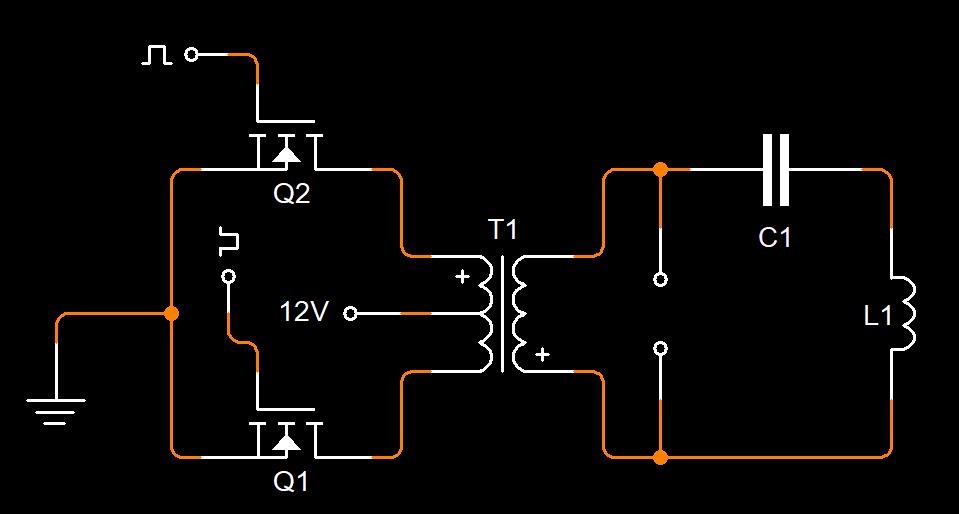
Chris posted this 21 March 2022
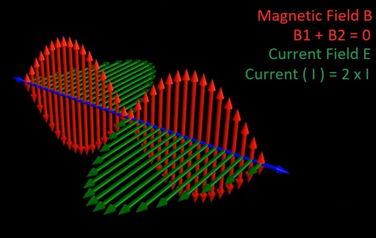
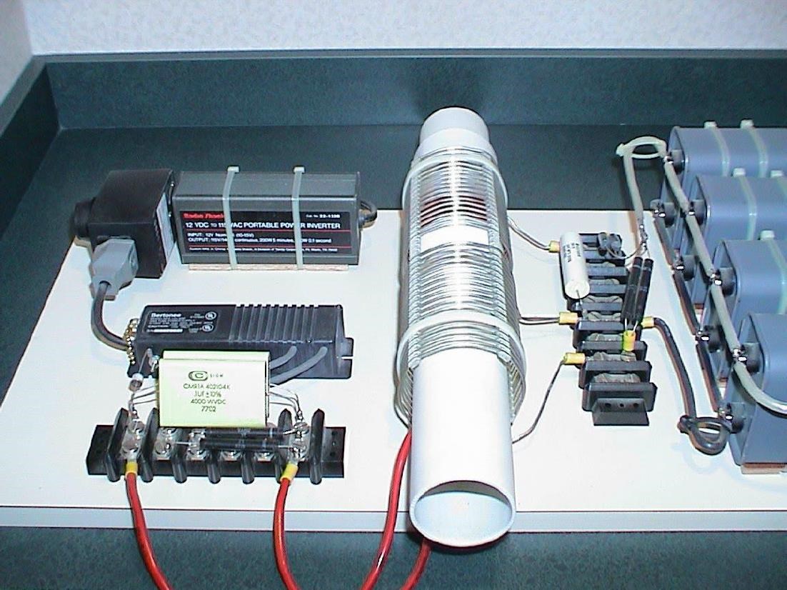
My Friends,

Electrical Energy is Kinetic Energy, in Nature. The Volume of Charged Particles q, moving at Velocity v, which is Voltage, and Current.
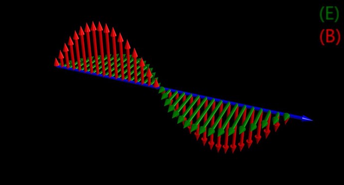
We know, from Experiment, that The Copper Coil is the Source of Charge, which is normally in a static, non moving state on our level, however we know charge moves on the macrolevel, as Electrons revolve around the Nucleus at high velocity.

Conventional Electric "Generators", power our world! But most do not even know how they work! Most don't even know that the Torque on the Shaft is an After Effect, of the "Generators" function: Electromagnetic Induction!

We know from Experiment, that Electromagnetic Induction is the "Generation" of a Voltage! Which is E.M.F, a unit measured in Volts.

Current is not predicted by Faradays law of Electromagnetic Induction!

When and only when Current flows, do we see Shaft Torque on the "Generator" in the form of Drag!

This means, the Magnetic Field is the Cause of Shaft Torque, and the Magnetic Field comes after we allow Current Flow, they are intimately linked, one is the other, but from a different view point.

The Magnetic Field is a necessity! We must have a Current, this is a Requirement for Power, so we must advance this entire incomplete Concept, and complete a 197 year old technology to gain what we should have, over 100 years ago, Free Energy!

As one Magnetic Field opposes, we must arrange another that also opposes! This Superposition gives us a 1 + -1 = 0 Vector Sum of the Magnetic Forces, or M.M.F. Thus Partnered Output Coils.

It is very important to understand, Electromagnetic Induction can occur more than once in a single Machine!

I have shown you how to do this here:


When you achieve 2 B x V like I have shown you all, then you need to work out how the Voltages are "Generated". Which is easy!

Remember what Steven Mark said:


This is what creates the Standing Wave:


But, instead, with two Magnetic Fields, each being the Source of the other, at Magnetic Resonance!


Each Coil, has Turns N, and when Loaded, each Coil has a Current I, which creates a Magnetic Field B, which changes in Time t, thus the very requirement for Electromagnetic Induction! In the Thread: Coil Geometry, I have shown you how to work out the Design Characteristics, to "Generate" a sufficient Voltage!

I am surprised more have not come forward with successes, as this is so easy, it is so cheap, and all can have access to this right now! There are no Secrets, it works just as the Electric Generator does, we now have no Shaft Torque, and have essentially circumvented the Negative effects, some call Lenz's Law.

We have no competition! We have no Rivals! We are Elite Electromagnetic Induction Experts and here to help YOU Succeed! All you need do is start your journey! No one else even comes close to our Expertise! Many have spent a lifetime trying, and FAILED Miserably! We succeeded, and they hate it!

Best Wishes,

   Chris

Chris posted this 05 February 2023

My Friends,

Science is catching up, slowly!

https://www.nature.com/articles/nphys3839


Please read the above article. Its worth the read! 

One must study what is being said, what is the Dirac Semimetal and the Weyl Semimetal:


Do you see the correlation to Partnered Output Coils?


Inside the Core, we have a series of Domains called: Antiferromagnetic Ordering or a antiferromagnetic System:

We have this very same Core Ordering when each Partnered Output Coil is Opposing each other, and the Core therefore does not travel the BH Curve as a Conventional Transformer would!

As is shown, we do have a Four Wave Mixing, because each Coil has a Primary and a Secondary Magnetic Field! Like Tom Bearden pointed out, the Whittaker Papers point this out.

This is because each Coil has:

  1. Induction
  2. and Self Induction


Do you see now, how far behind the Other Forums are! So many clueless goons out there that pretend to be Gurus!

We are Light Years Ahead of the Other Forums!

Best Wishes,

   Chris

We're Light Years Ahead!
Members Online:
What is a Scalar:

In physics, scalars are physical quantities that are unaffected by changes to a vector space basis. Scalars are often accompanied by units of measurement, as in "10 cm". Examples of scalar quantities are mass, distance, charge, volume, time, speed, and the magnitude of physical vectors in general.

You need to forget the Non-Sense that some spout with out knowing the actual Definition of the word Scalar! Some people talk absolute Bull Sh*t!

The pressure P in the formula P = pgh, pgh is a scalar that tells you the amount of this squashing force per unit area in a fluid.

A Scalar, having both direction and magnitude, can be anything! The Magnetic Field, a Charge moving, yet some Numb Nuts think it means Magic Science!

Message from God:

Hello my children. This is Yahweh, the one true Lord. You have found creation's secret. Now share it peacefully with the world.

Ref: Message from God written inside the Human Genome

God be in my head, and in my thinking.

God be in my eyes, and in my looking.

God be in my mouth, and in my speaking.

Oh, God be in my heart, and in my understanding.

Your Support:

More than anything else, your contributions to this forum are most important! We are trying to actively get all visitors involved, but we do only have a few main contributors, which are very much appreciated! If you would like to see more pages with more detailed experiments and answers, perhaps a contribution of another type maybe possible:

PayPal De-Platformed me!

They REFUSE to tell me why!

We now use Wise!

Donate
Use E-Mail: Chris at aboveunity.com

The content I am sharing is not only unique, but is changing the world as we know it! Please Support Us!

Thank You So Much!

Weeks High Earners:
The great Nikola Tesla:

Ere many generations pass, our machinery will be driven by a power obtainable at any point of the universe. This idea is not novel. Men have been led to it long ago by instinct or reason. It has been expressed in many ways, and in many places, in the history of old and new. We find it in the delightful myth of Antheus, who drives power from the earth; we find it among the subtle speculations of one of your splendid mathematicians, and in many hints and statements of thinkers of the present time. Throughout space there is energy. Is this energy static or kinetic? If static, our hopes are in vain; if kinetic - and this we know it is for certain - then it is a mere question of time when men will succeed in attaching their machinery to the very wheelwork of nature.

Experiments With Alternate Currents Of High Potential And High Frequency (February 1892).

Close