My Friends,
I am too early with this, risking my future plans, and fear it may even confuse others. But, here goes:
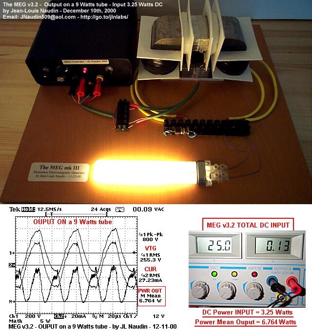
I have shared part of this before. Its a good example of Delayed Conduction. I used the small version of The MEG replication I built:
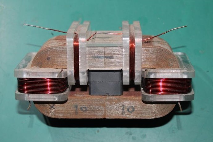
In investigation, to find other ways of achieving the results I had found in other experiments, I was trying a few different things:
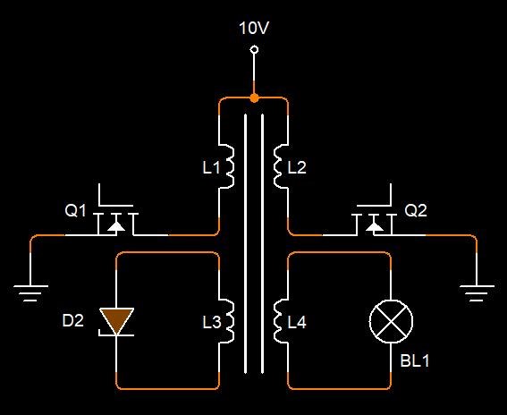
Some years back: 29.11.2015 I did an experiment. It was very interesting. The layout:
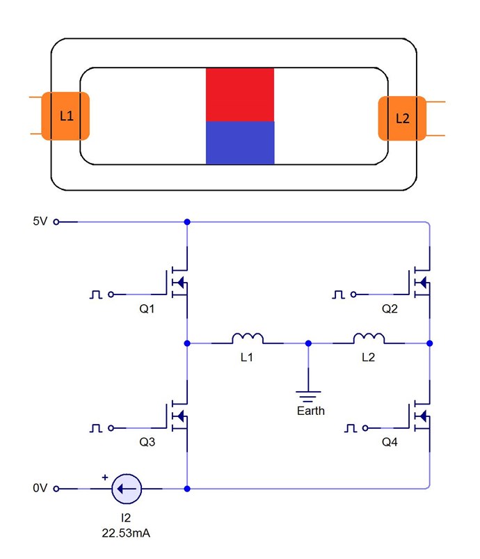
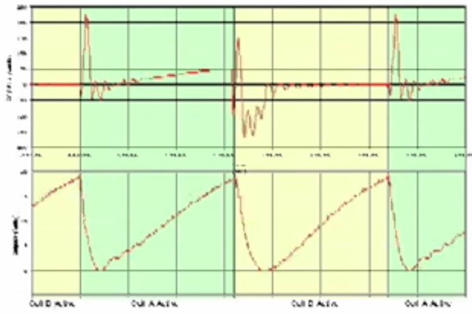
Very simple, but also very effective. With no Earth lead I could not make this work, with an Earth lead, I found a resonance at a very unusual frequency! in my setup I found at around 1208Hz, my Input went nearly to Zero.
Yet the device was shaking as if it had a few dozen watts through it.
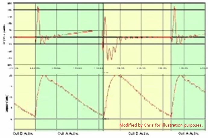
Input Voltage becomes nearly Sawtooth, Triangle Wave - but is in-fact Square, H-Bridge Switched DC
I have a sensing Coil on one leg - Voltage on the Coil goes up showing higher Voltage at resonance as one would expect
An example of Resonance. I had posted this to the net, none were interested!
Chris
Important: My Home made H-Bridge was not switched properly, there was a delay in switching Polarity's.
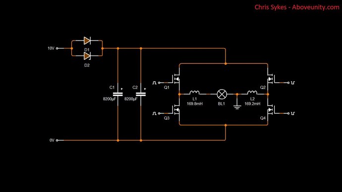
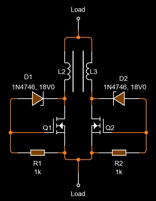
Here is a basic Circuit, an Old Circuit, I scavenged from an old Build:

Using only one of the Two Pin Terminal Blocks out to the Coils.
From Here:


I always try to recycle, even small simple things.
My H-Bridge switching was not clean, I was getting Spikes. I was getting Noise. This Noise appears to be a requirement for the Triggering of Magnetic Resonance. I call it Delayed Conduction.
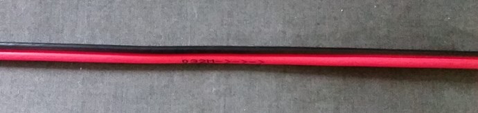
The Noise comes from Interference. From the Time Rate of Change of Current, the Ampere-Turns ( NI ), in proximity to a Secondary Coil. I have tried for a long time to give an example of Traces on a PCB:
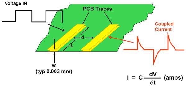
Ref: Parallel Wire or BiFilar Coil Experiment and many other places.
Think of each PCB Trace above, as The Partnered Output Coils. What causes the Spikes? It is the Rate of Change of the Current, E.M.F = N di/dt, that creates a Voltage, or as pointed out, dV/dt C = I.
- Capacitive Coupling.
- Inductive Coupling.
As the First Trace ( POCOne ) has a Changing Voltage, ( POCTwo ) will therefore have a Current Induced in it, if a Current can flow, E.G: A load is attached, is Conductive.
There are many situations where this will not work!
- If Trace one and two are both conducting the same Current at the same time.
- Some sort of Shielding is present and Trace two cannot see the change in Trace one.
- The list goes on...
However, when the Magnetic Fields are right, one can Pump the other! They work together. Then, we can call this: Magnetic Resonance!
This is why I encouraged more work on Fighters Thread: Romanian ZPM (Zero Point Module)
NOTE: This work follows almost exactly, Floyd Sweets early work:

Ref: P.8, March 1995 Volume 2, Number 11, New Energy News Letter
Resonance = Magnetic Resonance. At any one time the Coils are "Generating" as much Energy as is required to keep them in Operation. This is the reason the Input Current reduced nearly to Zero!
- The MEG does exactly the same thing when running correctly!
However it reaches this goal in another, already explained method.
- As does Graham Gunderson's MIT!
- As does Tinman's RT V3!
I may share a small video soon on this if all goes well.
Chris


 .
.


 )has reached all the needed requierements,i am now about a half year here and no one so far has made this "simple" Transformer.You now how long it did take you to get there and it is not so easy until you have it ones.
.jpg?width=690&upscale=false)