Important: Delayed Conduction in Bucking Coils

  • Topic Is Sticky
  • Topic Is Locked
  • 16K Views
  • Last Post 24 February 2024
Chris posted this 11 March 2019

My Friends,

The Effects of Delayed Conduction in Bucking Coils is important. What is Delayed Conduction? What is the point of this?

Delayed Conduction is specifically to get the Voltage on the Terminals of your Partnered Output Coils as high as possible in reason! Its the change in Magnetic Field that Creates Voltage, its the Opposition of Magnetic Fields that Pumps Current! 

Circuitry can also be employed to delay Conduction on the second Partnered Output Coil.

Ref: How to build your own Above Unity Machine


I gave an example of Delayed Conduction here.

As you can see, the Mosfets will only conduct when the Zener Diodes Conduct, this is rated to 18 Volts.

This means, the ends of the Partnered Output Coils must be at least 18 Volts, before the Coils can power any load!

We have seen this before! This is not new to those that have done the Study!


The MEG Demo Circuit

Where D2 represents a Bi-Directional TVS.


Ref: JLN MEG Replication


Ref: The MEG Team Data.

Where the Top Trace represents the Input Channels, and the bottom Trace Magnetic Resonance in the Output Coils, seen as Asymmetrical Regauging.


NOTE: JLN used a MOV in his MEG Replication. A MOV has similar Voltage to Current Characteristics! 


Ref: JonRB


Ref: Renesas Datasheet


Ref: The MOV or Varistor V I Characteristics


I want to stress the point of getting the Voltage on the Terminals of your Partnered Output Coils to a maximum without being disturbed. Input Creates a Voltage on your Terminals, then the Input is switched off. Then your Partnered Output Coils Conduct and we Pump Current.

Remember: Some of these Circuits may require an Earth Ground.

   Chris

Order By: Standard | Newest | Votes
Chris posted this 24 February 2024

Hello Adam,

This thread has not been very successful at pointing out what I meant to point out.

Everyone needs to think in terms of a "Lead up to the main event" so what was said, or explained in earlier threads, is meant for a more board result in the end. Gotta look at the bigger picture.

The point I meant to get to was:

There is a natural delay in Conduction from the Input Coil to POCTwo.


Here is how this works:

  1. Input Coil is switched on - Changing Current in Time!
  2. POCOne Conducts and a Voltage builds.
  3. POCOne's current builds as the Voltage Builds - Changing Current in Time!
  4. Sufficient Voltage is "Generated" in POCTwo, to now conduct, via the Diode, which was not shown at the time of this thread.
  5. Voltage keeps building in POCOne and POCTwo, until peak Voltage is reached.
  6. Your Input Coil is switched off at this point.
  7. POCOne and POCTwo's voltage decay over time.


When you do these experiments, you will see, there is a Natural Delay for all of these processes to take place! This is what stops these machines from effectively Running Away on themselves and gives us control over the process, with an external Frequency!


Faradays Law is Incomplete

I have introduced Asymmetry to a field that has always been bound to entirely Symmetrical Design Characteristics due to lack of understanding of Natural forces and Operations by others before me!

NOTE: You can see, the Voltage "Generated" in POC One and Two is a Function of the Building Magnetic Fields between each Coil:


Please remember, I had not shown the Thread: Chris's Non-Inductive Coil Experiment at the time of this thread! Timeline, it was after this thread!


Which gave us this Circuit:

With a very simple Input Circuit like so:

So, if you put a side the Circuits in this thread, Pseudo Circuits meant to represent the not yet introduced Circuits, and replace them, with these circuits, then you can see the exact fundamental processes explained here in this post.

You have to apply the fundamental processes of Energy "Generation", and merely extend them slightly to get Above Unity!!! I have been very clear on this for a very long time!

If you understand the Electric "Generator", then understanding Partnered Output Coils is not a stretch to understand! Both use the same fundamental processes as my videos point out!


Look for the Assist

The Assist is critical to making this all work! 

If you have a 70% Assist, then your Input Coil will use 70% less Power to get to the same Output Power, it's a flow on effect! You need to have the Input Coil get an Assist from POCTwo normally, or POCOne depending on how you have the Circuit and layout defined, you get the idea.

If POCOne and POCTwo Oppose each other, then one MUST Assist your Input Coil! Right! It just cant work any other way!

I know it is easy to get confused, I have been there, but the key is to push aside the confusion with experience on the bench and this all fits into place and makes sense.

Best Wishes,

   Chris

Adam posted this 24 February 2024

Hello Chris,

I have a few question for you.

I see at some point in the past you tried to delay the conduction on POC1 from the primary using a Voltage or Amp sensing board for Arduino then I suppose trigger an SCR or TRIAC?

Were you able to get that to work or was it to slow?

Did you end up in the end just using the dimmer circuit that basically counts time from the zero crossing to trigger?


Thanks.

Adam.

Chris posted this 13 December 2023

My Friends,

I have said in other posts, but I want to dedicate this post, to try to clear up some confusion that has entered, on this topic!

First of all, I am sorry for this confusion! I always try to be clear and try not to confuse others! I take a lot of time to try to be as clear as I can!

I think there is some confusion in the term: "Delayed Conduction"!

The Delay is from the Electromagnetic Wave Propagation, not from Circuitry, specifically. I tried to explain this, but I think my use of Circuitry as a Prop, to try to explain Electromagnetic Wave Propagation and the Delay, has confused people, I am sorry for this!

I tried to explain in my Series: "Chris's Non-Inductive Coil Experiment", about this Electromagnetic Wave Propagation and how there is a Delay in the Propagation of a Wave, inside and around the Core, to try to clear up this confusion.

NOTE: Electromagnetic Wave Propagation takes Time, this Delay can change depending on Core Material, Design Specifics, and other factors.


Partnered Output Coils take Time to reach Conduction Voltages, break over Voltage on the Diodes, around 0.5 - 0.7 of a Volt, because the Magnetic Fields building in Time also takes Time, so we have a Delay, between the Coils. So, the Time it takes, from Input Coil, TOn, to POCOne Break over Voltage, has a Delay in Time, its not instantaneous! The same is true between POCOne and POCTwo.


Delayed Conduction is NOT About:

  • Circuitry


However, Circuitry can create a Delay in the Conduction of a Specific Circuit! Its an Analogy to a greater meaning.

Delayed Conduction IS About:

  • The Time is takes for an Electromagnetic Wave to Propagate to Point B from Point A, and do useful Work.


I am very sorry if this has confused Others! I did not mean to confuse others! Again, I have tried to explain this more, in my videos, and in other posts.

Best Wishes,

   Chris

Chris posted this 18 December 2021

Hello Scalarpotential,

The Core is a Lenz, all it does is Focus the Magnetic Flux and the "Change" of this same Magnetic Flux, in Time ( t ), with a Propagation Delay.

So, the Core must be seen for what it is, having "Aspect Ratio" and thus Time Delay:

Uniform space has only two parameters:

  • 1: aspect ratio.
  • 2: time delay.

Aspect ratio defines the shape of energy entering a given region of space, but not its amplitude. Velocity or length define the time during which the properly shaped energy can be accommodated by a region of space. Aspect ratio is really a definition of the relative compatibility of adjacent regions of space. Does flowing energy current largely travel unimpeded through an interface, or does it largely reflect at the interface? Space has quiet zones through which energy glides virtually unreflected. There are also noisy zones where energy current becomes incoherent, bounces about and splits apart. Noisy zones in space have either rapidly changing geometry or rapidly changing impedance


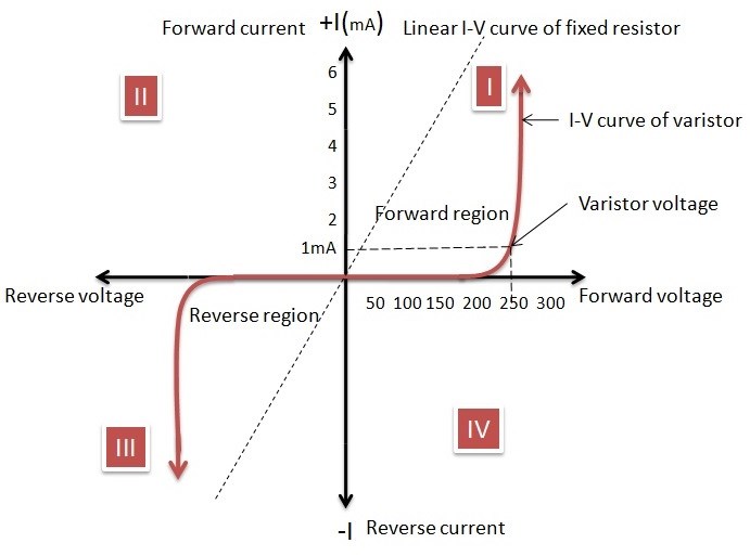
Aspect Ratio, This is the Core Material, the Energy is Magnetic Flux, or The Magnetic A Vector Potential, which is Amperes per Sq Meter. One Gauss = 79.77 Amperes per Sq Meter.

No, ALWAYS there must be a Bucking, Opposition of Magnetic Fields! But in Order, there is an Order to the Action Sets!

Magnetomotive Force ( M.M.F ) is measured in Units of Current ( I ) and Turns ( N ), which is Ampere Turns ( NI ) and H is the Magnetic Field Strength, which is different again, but measured in the same Units, NI:

magnetic field strength, also called magnetic intensity or magnetic field intensity, the part of the magnetic field in a material that arises from an external current and is not intrinsic to the material itself. It is expressed as the vector H and is measured in units of amperes per metre. The definition of H is H = B/μ − M, where B is the magnetic flux density, a measure of the actual magnetic field within a material considered as a concentration of magnetic field lines, or flux, per unit cross-sectional area; μ is the magnetic permeability; and M is the magnetization. The magnetic field H might be thought of as the magnetic field produced by the flow of current in wires and the magnetic field B as the total magnetic field including also the contribution M made by the magnetic properties of the materials in the field. When a current flows in a wire wrapped on a soft-iron cylinder, the magnetizing field H is quite weak, but the actual average magnetic field (B) within the iron may be thousands of times stronger because B is greatly enhanced by the alignment of the iron’s myriad tiny natural atomic magnets in the direction of the field.


H is the Magnetizing Force, and not Magnetomotive Force, where, the Strength of the Magnetizing Field ( H ), and the mean length ( L ) of a solenoid are equal to the M.M.F. M.M.F = HL. So they are different things.

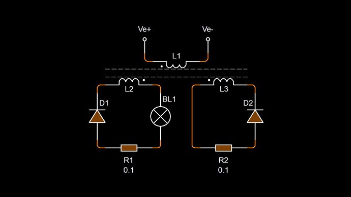
At Magnetic Resonance, the Core serves as a Medium, if you like a Transmit and Receive Medium, which facilitates the Coil to Coil Interactions required, but the same can be achieved with No Core also! So a Core is not necessary at all, I have found a Core can make results more fruitful in most cases.

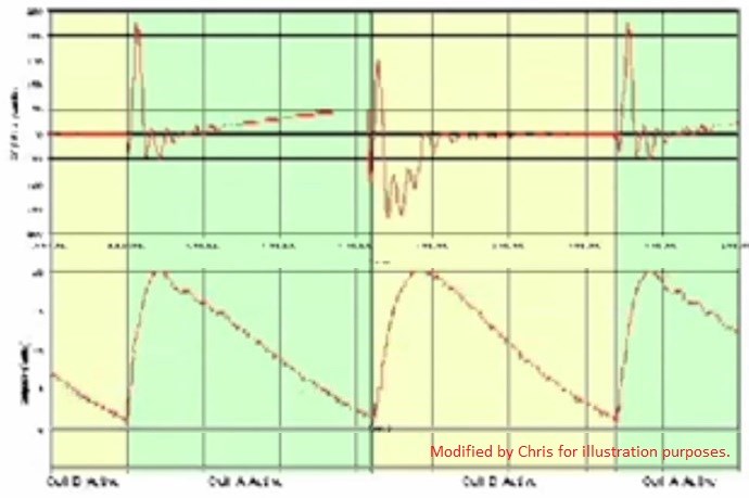
At Resonance, we find Maximum Amplitude in Output Voltage ( V ) for the Minimum Input Current ( I ). Magnetic Interactions are at the same Propagation Delay, and no longer or shorter. An ideal, lossless Transformer becomes a realisation and Energy Gains come from the Time Domain.

Imagine Magnetic Resonance as a Shaft Driven "Generator", Speed Up, or Slowed Down, to find the Ideal Magnetic Interactions between the Rotor and Armature Coils. In measuring this, one would find 180 Degree Phase between each Coil, and approximately the same MMF Amplitude. At Magnetic Resonance, Shaft Torque would be at minimum, just like the Timing in a Combustion Engine. An Engine with Advanced or Retarded Timing does not run smooth and thus is not as Efficient!

The same is true of these Magnetic Interactions!

Best Wishes,

   Chris

scalarpotential posted this 17 December 2021

Is this, the magnetic  processes in the core like resonance and EPR, the reason for what Bearden said is needed: non-linear control and oscillation  theory, to make the fields additive instead of opposing?

nb. MMF isn't current because it's called ampere-turns, but H=MMF=magnetic field intensity  is directly proportional to current that produces it, n is the multiplier.

Chris posted this 15 December 2020

My Friends,

I want to clear up, some possible confusion here!

NOTE:

  • P = Primary.
  • S = Secondary.
  • a = Active.
  • n = Neutral.


Regarding Delayed Conduction, here we see No Delay in Conduction:

In the above Example, we are holding the Tension, between L2 and L3 the Same! There is no opportunity for L2 and L3 to differ in anyway! All Electromagnetic Induction comes from the Primary Coil! L2 and L3 act as one Wire, only doubling the Wire Cross Sectional Area, or AWG.


Delayed Conduction is really about "Letting the Tension Differ" between the Coils, or breaking the Conduction, normally held steady. A Delay in the Conduction allows for the Currents in the Coils, therefore, the Magnetic Fields to Slap Together.

This:


is the same as this:


This, is the Slapping together, in other words, a function of Electromagnetic Induction: E.M.F = -N dΦB / dt

So L3's Voltage is a Function of the Changing Current in L2.

Asymmetry is the Key! Asymmetrical Regauging is the only path forward. Above, in the Second Video, we see Time as a Symmetrical function. Equal Rise and Decay in Amplitude. We must make this Asymmetric, using Coil Resonances, the Time it takes to climb to max Amplitude, Rise over Run, will be at peak, when the Coil Resonance is Found, we have no XL or XC and the DC Resistance of the Coil is all that's left. This means, minimum Input is required to reach Peak Output Voltage.

Best Wishes,

   Chris

Chris posted this 03 March 2020

My Friends,

Some ask questions on Delayed Conduction, some don't seem to understand the significance. When Tinman has his very early successes, I posted this comment:

@Tinman,

Does your Transistor and Diode Conduct at the same time? If not, what's the time delay between the two?

I believe this is where the confusion over "Shorting" has entered.

   Chris Sykes
       hyiq.org

Ref: Partnered Output Coils - Free Energy


I urge all here, especially the ones doing lots of experiments, don't forget about Delayed Conduction, it can help get your Output Up.

Best wishes,

   Chris


Chris posted this 09 October 2019

My Friends,

I want to share some information that is of great importance! In the past you have heard me talk of the Coils Slapping Together! When they do, we get a Standing Wave! The Video I have shown in the past to get this mental image across is:


The Image I have shown is:


Now, I want to show you a Video from Graham Gunderson, please go give him a thumbs up, his expertise is invaluable! Anyway, this video shows you the same effect and the result:

Keep in mind, Graham says: "The key here, is Rise Time and that's what this video is about" @1:52


In the above Video, we see the effect of the Slapping together, the faster and thus the harder, the better!


But Why?


Electromagnetic Induction, the faster the Time Rate of Change, the greater the E.M.F!

See the Amplitude of the waveform:


See the Amplitudes, the difference, I have marked in Red and Orange. This is important to see and understand! 

Remember, I = V / R, so the Higher V is, the higher I can be!

Electromagnetic Induction, the Time Rate of Change of the Magnetic Fields is the Key here!

   Chris

  • Liked by
  • Vidura
  • cd_sharp
patrick1 posted this 24 September 2019

Hi Vidura. great answer. thankyou so much, i have been thinking about alot during my evenings experiments...  COP+ is still illusive (in transformers)   ...  practically speaking.  my250N' transistors should arrive soon.  i am really eagre too work more on fighters replications. i love his work. its looking really promising TY all

Chris posted this 22 September 2019

Hey Guys,

Vidura, another way is also possible. As your experiments progress, you will find it. Its a very simple method. wink

   Chris

Vidura posted this 22 September 2019

Hey Patrick, About the serial inductor I'm not sure in this case, because the interaction of the POC is thru the magnetic field (core). Regarding the output, there are four ways to increase: rising the Q-factor of the POC, rising d/phi d/t (Frequency), rising the cross sectional area of coils/core and finally increasing the energy (potential) of the driving pulse. Regards Vidura.

patrick1 posted this 22 September 2019

very nice Vidura,

how do you feel about using a series inductor for tuning ?. ,  also what do you think you need too do for more light ?, when output voltage is already very high,      do you need more than a lower value mov ?

Jagau posted this 22 September 2019

Hi vidura
Excellent video, well done and interesting
your PWM seem very clean with a real DC square wave.
thanks for sharing
Jagau

Chris posted this 21 September 2019

Hey Vidura,

Excellent! Thanks for sharing!

I left a message:

+1 Beautiful Vidura! The Voltage on the Varistor is showing the Work Cycle, a Linear decay over time of the Voltage, @3:54, the decay is not an exponential, its linear.


The Linear decay over time indicates you have the very same effects as Asymmetrical Regauging, this is the Work Period, you're using your Partnered Output Coils to pump Current, Electrical Energy, V x I over Time.

You show the importance of your switching tool, it is so extremely useful!

For all:

Floyd Sweet used a technique, well known, but not widely used for most situations.

CSA is Cross Sectional Area, for a circle is Pi r2 for the Cross Section, for a rectangular or square core: l x w for the Cross Section, this extremely important technique means, as we increase the Area the Coils are exposed to, we need less turns for the same Voltage, as a result we get more Current due to the Coils DC Resistance being much less!

By increasing the area of the Wire Exposed to, or occupying the fluctuating Magnetic Field, Sparky doubled the output. Exact proportions/ratios of Space-Filling Volume of windings to output have not been determined with precision, but a relation is evident.

Ref: Floyd Sparky Sweet - LabNotes


Your post is extremely important! I hope others pay attention, learn as much as they can from it!

I hope this helps!

  Chris

Vidura posted this 21 September 2019

Hello All.

Here an experiment which I have performed inspired by the latest video about magnetic resonance. I have often the feeling when experiments failed, that it was related to the coils. Often I just have made them in hurry, not accurate at all. So this time I took the time to perform a proper tuning of the selfresonant frequency of the POC set. First I tested each of the coils individually on the core, with both coils together it becomes more tricky I found. Then I started to remove turnes from the one with lower frequency, until both had the same selfresonance:

For the individual tuning I attached only the positive output of the SG to the ground of the scopeprobe, in the final test with both coils the positive of the SG is attached to one coil, which acts as antenna, and the scope to the other coil.

Here the video of the experiment on delayed conduction:

Vidura

Chris posted this 17 September 2019

My Friends,

Some time ago I posted this post:

Bump!!!

For those that do not comprehend, have not been following, but wish to comprehend and follow, to learn something and to achieve a common Goal:

Action: - (Primary Coil) - Your Input. A Magnetic Field, a result of Current Flow in your Primary Coil, that will likely have a Reactive Component. Considered as the Prime Mover.

Reaction: - (Secondary Coil) - Typically considered as a Negative result on the Action. Lenz's Law (the -), a negative result of the Secondary Coil on the Primary Coil.

Counter-Reaction: - (Secondary Coil) - Another Negative result, but this time assisting the Action, the primary, or the Action, but at the same time Countering the Reaction. Lenz's Law (the -).

The two Secondary's are what I call Partnered Output Coils!

These principals can be arranged in many configurations that may result in a working device, and the opposite is also true.

Ref: EMJunkie, me Chris


Follow the rules and it will work, its not hard, its just a case of adjusting the way of thinking a little.

   Chris

getreal156 posted this 17 September 2019

Hi Patrick,

Thanks mate !

I have several mosfets lying around that I collected over the years and I bought a bunch a while ago incl. the IRFP250N (which I'm using right now). I just ordered some IGBT's for switching of L2. I'm using a 20K resistor already between source and gate. Mosfets are still blowing up.
At this moment I'm using dirt cheap ferrite E and U cores and some conical ferrite CRT cores. I think there is some thing to gain with other materials but I think I'm doing fine with what I have right now. My results tell me I should continue experimenting with ferrite. Also Melnichenko is a big motivator for me in this regard. His devices are also simple and very effective. https://vk.com/id285085326
As a side project I'm also working on some coils that he is showing. Basically Mr Preva experiments in overdrive I also think that too many windings on the coils makes things more complicated to tune 

  • Liked by
  • Chris
patrick1 posted this 17 September 2019

Hey Getreal. glad too hear your are working on this circuit too, - i have been thinking about building another desk, instead of more storage space. - i have nothing but time these day.s - so i simply must make more progress. - so i am going too start working on this circuit also. - with an iron transfformer.  what kind of transformer are you using ?

also may i suggest a 10k resistor from base too emitter. - all transistors have different gate capacitances, thus require different pull down resistors , and some require non at all, but that is quite rare in my experience. -   if they dont turn off, they can easily blow for many reasons related too that.

also you may want too order the same as myself and a few others.  IRFP250N . dirt cheap on ali express

https://www.aliexpress.com/item/32820322815.html?spm=a2g0s.9042311.0.0.40ba4c4d25WqU3

  • Liked by
  • Chris
getreal156 posted this 17 September 2019

Hi Cris,
What really happens in the Mr Preva experiment (magnetically) is still a mystery to me. I had it on the bench again yesterday and I will repeat it probably many times more to get a deeper understanding.

  • Liked by
  • Chris
Chris posted this 17 September 2019

Hey Guys,

I have used this image before, here and here:


Iron Man and Iron Patriot, or War Machine, a name I dislike.

Now I want to share a Video:


Lets stop for a minute, think about the Action shown. Two Balls Fired at each other, in slow motion so you can see it.

Standing Waves, they are the same exact thing as we see, but Electromagnetically, two Magnetic Fields slapping together with a Force! A Force, Time Rate of Change of the Magnetic Fields is Electromagnetic Induction! Creating a Voltage!

Our Partnered Output Coils work together, Oppose, to do exactly as the Balls fired at each other, or Iron Man and Irom Patriot were doing, a Standing Wave:


Standing Wave:


Electromagnetic Wave:


This Standing Wave is the result, the addition of, two separate Waveforms, each travelling in the opposite directions, as indicated above, both in the Video and in the Image of Marvels Super Hero's.

Note the direction of the Blue Arrows:


Many times on this site, we have been through the above image, but I ask you:

Think Magnetic Resonance!


If the directions of the two signals are such that opposite H-fields cancel and E-fields add, an apparently steady E-field will be created. The energy density of the fields remain as calculated above, but the value of the E-field will double from E / 2 to E.

Ref: Floyd "Sparky" Sweet


The E Field is the Green Arrows, the Red Arrows are the Magnetic Field, they sum to Zero, Equal and Opposite, shown above. Again, please notice the E Field has doubled:


Again, here:


And, remember this image? From Here.


Again, The Mr Preva Experiment, it teaches us this importance.

I am sorry for rambling, but I think its important to bring up at this stage. wink

   Chris

  • Liked by
  • cd_sharp
getreal156 posted this 17 September 2019

Hi Vidura,

Good point. I didn't look into this yet.
Your offer for help is much appreciated, but first let me do my home work before I bother you with the details. 
I have several types of mosfets lying around and I have to look up the min/max gate values and I have to dig into TVS values.

Maybe another option is to replace the mosfet by an IGBT. I think these allow a higher gate voltage.

Thanks for the tips ! 

  • Liked by
  • Chris
  • cd_sharp
Vidura posted this 17 September 2019

Getreal, TVS device for such a low voltage as the max gate source voltage will hardly be found, usually zener diodes are used for gate protection. Can you gif the specifics of your MOSFET so I can suggest appropriate values. Vidura.

  • Liked by
  • Chris
  • cd_sharp
getreal156 posted this 17 September 2019

Hi Cris, 

"Yes time is such a problem, they keep us busy so we cant get other important things done. wink "

Not many people understand the true nature of this world and how it is organized but what you are saying is actually very very true !!

Thanks my friend!

  • Liked by
  • Chris
  • cd_sharp
getreal156 posted this 17 September 2019

Hi Vidura,

Thanks for the suggestions.
I have only few turns for the trigger coil and between 14 and 90 turns max. for L2 and/or L3. Comparable to the coils of Andrej Melnichenko. So far this gave me better results, less noise and lower voltage spikes compared to coils with hundreds of turns of thinner wire.

Do you think that Adding a TVS in series with the zener could work? I don't have them lying around and I was planning to order some. 


  • Liked by
  • Chris
Vidura posted this 17 September 2019

Hey getreal156

regarding the failure of the mosfet, it is likely due to overvoltage. Could be on the gate, check if the zener has the correct value, below the max GS voltage rating, check also if the DS voltage of the mosfet is sufficient, if you have much windings on the POC very high voltages can appear, I have measured several thousends of volts in occasions.. 

By the way I also have problems with this short days of only 24hours latlylaughing

Vidura

Chris posted this 17 September 2019

Hey GR,

Excellent, I am very happy to hear!

Yes time is such a problem, they keep us busy so we cant get other important things done. wink

It sounds like your spot on target GR, Nice!

Any questions, let me know, I am happy to help where I can, just remember, Magnetic Fields are doing exactly this:


   Chris

  • Liked by
  • cd_sharp
  • Fighter
getreal156 posted this 17 September 2019

Hi Cris,

Maybe I was not really clear. I'm actually working on the exact same circuit you are proposing and I'm experimenting with delaying alternatives for D1. This can be a Zener, a MOV or a combination with a mosfet. 
I tried CD's setup but I'm also experimenting with different delay circuits using a mosfet and zener. Like I mentioned the mosfet is blowing up. They probably fail due to high voltage spikes on the gate. 

ps.
Don't worry Cris, I'm a devoted follower of your work and this forum. I'm literally reading and analyzing ALL the posts and information here . I'm not an ee but I do have sufficient electronics skills and I believe that I understand the concepts and theories, as you have presented, quite well. The only problem I have is a lack of time for experimenting. Full time job, family with small children and only 24 hours in a day.

Chris posted this 16 September 2019

Hey GR,

If I may offer some advice, CD has done a lot of work here and is doing really well, see here.

Working together as a team may be of great benefit?

Simple Starting Circuit - Some parts upside down to make you think backwards.

Where: D1 is a Delayed Conduction Device, Zener Diode and a Mosfet or a MOV or a TVS or similar device.


You will find this at the top of the page: Here.

CD is doing really well, its just timing now, and he is there!

   Chris

getreal156 posted this 16 September 2019

Hi all,

I'm experimenting with the delay circuit. I replicated the circuit below (one side) but this resulted in blowing up the fets.
Not 100% sure but I think this happens because of high voltage spikes on the gate. I started off with a 6K resistor and increased to 20K resistor. The fet is still blown up
Maybe I should add a TVS in series with the zener to clamp down the spikes?

Not really sure what to do.
I would appreciate if some one could give some advice.

  • Liked by
  • Vidura
Chris posted this 18 July 2019

Hey Patrick,

Your questions are answered Here.

Pretty much, around 10% Duty, and tune Frequency, but these settings may vary, you have to tune for the best performance, what I have given is a guide.

   Chris

  • Liked by
  • Vidura
patrick1 posted this 17 July 2019

Thanks buddy i was about too ask a question similar too this also, - which was, what kind of duty cycles should i be looking at for the above circuit ?.- i found a h bridge in my junk room made from SS relays, and it should be easily adapted too run this circuit for resonance testing ;-).  cheers,

or are you suggesting i should tie a noose around my Fets and just do 50% on %50 off.

hehe makes sence, but a little intimidating, -    ALRIGHT LETS GO LEMMINGS !

  • Liked by
  • Chris
Chris posted this 17 July 2019

Hey Patrick,

A Mountain Climber has a lot to consider when making a Climb.

Climb up a Mountain and the Wind is behind you, then your Up Hill Climb is assisted, the Climber has two Forces, Gravity in Resistive Direction and Wind in the Assistive.

Partnered Output Coils are the same, One Assistive, one Restive.

Make a point of measuring your Currents, it will make things easier if you're knowing what your Coils are doing.

Use a similar setup to this:


This will make life much easier!

Simply by applying the Right Hand Grip Rule, you will know what your Coils are doing.

   Chris

patrick1 posted this 16 July 2019

Arrrggg, well,  im used too leading by miles, or following - and i dont feel like either right now,  but thats life in this field. -   anyways i have been busy on motors all day, ...   but tomorrow, i want too get back into my transformers, and trying resonance ,  also applying principles too my transformer, that got my linear motor into the COP 6 region  (with strong neos)... thinking about it last night, - seems like currently my best shot too getting good numbers from bucking coils, -  i want too say its good fun playing with LENz free emf's and trying too buck the most out of them,.

  • Liked by
  • Jagau
  • Chris
Jagau posted this 15 July 2019

Nice video Patrick

You are ahead

Delayed Conduction in Bucking Coils is to acheive A.U.

but the configuration of the 3 coils is aloso very important (not 4)

Jagau

  • Liked by
  • Vidura
  • Chris
patrick1 posted this 15 July 2019

Hey Jagau,  i have a bunch of 6foot iron ground rods in my back yard. - about 10 years old and quite rusty, but that might help ;-D...  so naturally i was happy too test your question, thanks for that.  vivid response !


also i have gone onto testing my newer transformer with 4 coils, - because the gains from 2 output coils is evident, even at this stage, and i have not been doing any resonance testing yet, .  but i want too try bouncing some magnets around, - preliminary tests show much potential difficulty due too the magnets replacing the iron, causing core problems im not familiar with, - only time will tell.

  • Liked by
  • Chris
  • Jagau
Chris posted this 14 July 2019

My Friends,

CD_Sharp has done some Experiments on Delayed Conduction.

His last Experiment is worthy of mention here. CD has shown How Delayed Conduction works in this video.


This is a very important Video and Experiment! CD's Post can be found Here.

   Chris

  • Liked by
  • Jagau
  • Vidura
Jagau posted this 14 July 2019

The more you increase the coupling factor, the faster the energy transfer will be,

but the less the means used to close and open the circuit quenched at your satisfaction and also have less time to cool,

Tesla very often used coupling factors very low of 0.05 to 0.2  

I am just having an experience with POC that proves this and it works

Hey Payrick, have you tried to make your coils ringing, using only the inductance and natural capacity of your coils? I also had good results with that.

Jagau

  • Liked by
  • Chris
  • Vidura
patrick1 posted this 14 July 2019

Okay that makes scence ,  i get that keeping the secondaries close too the core, but further away from the primary would be befinicial too reducing coupling, 

infact its more elegant that joggling with resistances. - but can you tell me where the benefits would manifest ?

im about too being in a fresh built transformer, and i want too try and incorporate this thinking

Jagau posted this 13 July 2019

hello Patrick

The best way to reduce the K factor is to space the coils

example with tape electrical insulation

but not to move the coils away from the core.

Jagau

  • Liked by
  • Chris
patrick1 posted this 13 July 2019

Just found a good document that shed some light on coupling,  i think the easiest way too degrade the coupling is have a spacer between the core, and the spool, too create a coupling gap. ,  also possibly print a spool that has a few degrees of eccentricity too it in relation too the core. but what would you say the most obvious side effect of this,after its done right,  that we should be looking for ? ;-)

  • Liked by
  • Jagau
  • Chris
Chris posted this 12 July 2019

Hey Patrick,

Iron is just as good as any other Core Material as long as you have an air gap.

In saying this, I have used some cores that are "Slugs" they just don't seen to work, so you will have to try things if you don't get results, however, you already are!

The Coils Coupling Coeficent ( K ) is best if there is a Coupling of the Partnered Output Coils of about 0.5, and a Coupling of about 0.5 of the Input Coil to only One Partnered Output Coil and less to the other Partnered Output Coil maybe 0.3 or so.

This makes for easier Delayed Conduction.

Good work Patrick! Keep it up!

We truly are Light Years ahead of the other Forums!

   Chris


  • Liked by
  • Jagau
patrick1 posted this 12 July 2019

Hi Boys !!!. couldnt agree more, there is no magic, - i just wanted too relate too some phreaks on eevBLOG.  - anyway they locked my thread before i had any real answers, -  at least my account was not immediately banned with this mention free energy.  lol, its like there is some kind of conspiracy....  funny thing is, i bet they would all loveee too talk about it in person.  weaklings.

- btw Chris, its funny you should mention developing my existing transformers, - i know that it may be a handicap, working with iron, - but if it is possible,  its the first thing i want too learn, - and i have been doing many tests and compiling data into tables. - based on my chopped up MOTs, and basic configurations.   - so far the data is showing, - the windings want too be tight, and close, and that output loads resistances are critical too maximum wattage,  and i think something important will emerge very soon

  • Liked by
  • Chris
  • Jagau
Chris posted this 12 July 2019

My Friends,

It should be noted, anyone with an insy bit of Electronics knowledge, will be able to affirm this fact; What I have shown you is not Conventionally Understood Behaviour for Coils!


Coils Natural resonance is much higher than the Frequencies I am showing you! The only way, normally to get Resonance on Coils like these it to add Capacity, a Capacitor! We are not doing this!

Here is an example:


You can see: 550KHz is the Natural Resonant Point on that Coil.

The Coils Natural Resonant Point is a combination of Distributed Capacitance between the Turns of the Coil, a Capacitance, and the Inductance of the Coil. This gives Inductance ( L ), Capacitance ( C ) and Resistance ( R ) or LCR Resonance = 1 / 2π sqrt(LC) = Frequency in Hz and the Resistance is considered Damping ( ζ ).

Even with an Earth, the Coils lowest Resonance would be: 550Khz / 0.25 = ‭137.5‬KHz still hundreds of thousands of Hertz away from what I have shown you!

My Coils have much fewer turns, my Natural Resonance Frequency will be very much higher than the video shown.

I have shown a few hundred Hz, we are many thousands of Hz lower! What I have shown you is a different Resonance than typical LC Resonance. The Coils Capacity has changed drastically! This is a direct result of the Opposing Magnetic Fields.

This is new, its not in any textbook I have read, not in any literature anywhere, not anywhere I have been able to find!

   Chris

  • Liked by
  • solarlab
Chris posted this 11 July 2019

Hey Patrick,

There is no Magic!

Electromagnetic Induction is not Magic. We understand it fairly well, its just Science stopped exploring it when it was in its infancy!

Improving what you had in the last video will give you greater output, you must work on that, focus on increasing the Output and reducing the Input. This is one way its done:


Other ways also exist, but I think we don't want to diverge to much or we might see some confusion.

   Chris

  • Liked by
  • solarlab
patrick1 posted this 11 July 2019

Hi Chris,  i liked your video,  i concede this is not a magic core, .  but can we turn that into a magic machine with 2 magnets and a secondary ?

BTW this is fun, i have a few more elaborate methods i want too try, - *from my dreams...    and then i will come back down too earth, and use your 10years experience too help peeps in this world....     &&im still working on my pendulum water pump, and newman motor !!....  so this would be a rite cherry !

** see what i grabbed off the eevMAGIC forum.   http://www.kazumi-kikou.com/pdf/3007.pdf   cool IC


ati ; i love the diesel electric hybrid soundtrack

  • Liked by
  • Chris
  • solarlab
Atti posted this 11 July 2019

Hey Chris.

I'm still trying.
  Yeah, I know it's just an effect.
But this is probably important.

  • Liked by
  • Chris
  • solarlab
Chris posted this 10 July 2019

Hey Atti,

@ 2 : 58 in your first video, you achieve the result.

  • Tap the Coils with a Ground Wire and the Sinusoidal Wave form appears on the Scope.


Perhaps a bad Ground? Try pouring water around your ground pole. Are the Coils CW CCW Wound? This gives the best result. but is not necessary! Also perhaps you're too high Frequency, a big machine like that you should only be down around 300Hz, the time base ( 500us ) indicates you might be too high Frequency?

Please remember, this is only an Effect, a step towards an Asymmetrical Device.

   Chris

  • Liked by
  • solarlab
Atti posted this 10 July 2019

Hi.

I would ask for help from others. Those who have the opportunity.
Chris's experiment (Magnetic Resonance) is repeated, I tried.

My problems:
-The capacity between the coils is not satisfactory. That's why I added an external capacity. (in the second half of the video)
- Without external capacity, I can't repeat the experiment, but there's no waveform.
(this video also shows external capacity at 6:05 min 

)
-In my uploaded video, none of the inductances shown in the background is satisfactory.
- Earthing in one layout is not satisfactory either.
- Earthing with the oscilloscope sometimes drops.
-The performance (or resistance) of the bulb changes the resonance.

I encourage everyone to repeat the experiment.
- Is there any other problem?
-What kind of?
-Does replication succeed?
-What are your experiences?

  • Liked by
  • Chris
  • solarlab
Chris posted this 10 July 2019

Hey Vidura,

As promised, a Ferrite Core Demonstration:


Yes, the Ferrite Core does work, but as expected, the Resonant Frequency is much higher: 2.65KHz

Please excuse my Core rant at the end, it was directed at all the Magic Science Guru's on the other Forums. I like to set the record straight is all. Some maintain Magic Cores... Magic Ferrite, its all a bunch of complete rubbish!

I hope this helps!

   Chris

  • Liked by
  • Vidura
  • solarlab
patrick1 posted this 09 July 2019

Yes buddy, i feel that way too, -  we have come a long way.  and i feel we are now on a roll.,  - the methodical methodology means one thing too me, -   building muscle memory and invaluable experience.  - even though, the more work i do, - the more doorways become avaliable too me. = more than i can explore day too day,  -  im really enjoying the push and pull

  • Liked by
  • Chris
  • solarlab

Topic Is Locked

We're Light Years Ahead!
Members Online:

No one online at the moment


What is a Scalar:

In physics, scalars are physical quantities that are unaffected by changes to a vector space basis. Scalars are often accompanied by units of measurement, as in "10 cm". Examples of scalar quantities are mass, distance, charge, volume, time, speed, and the magnitude of physical vectors in general.

You need to forget the Non-Sense that some spout with out knowing the actual Definition of the word Scalar! Some people talk absolute Bull Sh*t!

The pressure P in the formula P = pgh, pgh is a scalar that tells you the amount of this squashing force per unit area in a fluid.

A Scalar, having both direction and magnitude, can be anything! The Magnetic Field, a Charge moving, yet some Numb Nuts think it means Magic Science!

Message from God:

Hello my children. This is Yahweh, the one true Lord. You have found creation's secret. Now share it peacefully with the world.

Ref: Message from God written inside the Human Genome

God be in my head, and in my thinking.

God be in my eyes, and in my looking.

God be in my mouth, and in my speaking.

Oh, God be in my heart, and in my understanding.

Your Support:

More than anything else, your contributions to this forum are most important! We are trying to actively get all visitors involved, but we do only have a few main contributors, which are very much appreciated! If you would like to see more pages with more detailed experiments and answers, perhaps a contribution of another type maybe possible:

PayPal De-Platformed me!

They REFUSE to tell me why!

We now use Wise!

Donate
Use E-Mail: Chris at aboveunity.com

The content I am sharing is not only unique, but is changing the world as we know it! Please Support Us!

Thank You So Much!

Weeks High Earners:
The great Nikola Tesla:

Ere many generations pass, our machinery will be driven by a power obtainable at any point of the universe. This idea is not novel. Men have been led to it long ago by instinct or reason. It has been expressed in many ways, and in many places, in the history of old and new. We find it in the delightful myth of Antheus, who drives power from the earth; we find it among the subtle speculations of one of your splendid mathematicians, and in many hints and statements of thinkers of the present time. Throughout space there is energy. Is this energy static or kinetic? If static, our hopes are in vain; if kinetic - and this we know it is for certain - then it is a mere question of time when men will succeed in attaching their machinery to the very wheelwork of nature.

Experiments With Alternate Currents Of High Potential And High Frequency (February 1892).

Close