How to build your own Above Unity Machine

  • Topic Is Sticky
  • 11K Views
  • Last Post 04 November 2023
Chris posted this 01 December 2018


You Will need:

  1. One Input Coil
  2. Two Output Coils
  3. Patience
  4. Support


You need to follow the basic plan laid out here:
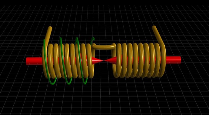


NOTE: Partnered Output Coils can be wound either CW / CCW or CW / CW Flipped.

  • CW is Clockwise.
  • CCW is Counter Clockwise.


I prefer CW / CCW.

You will need to make sure your Output Coils have Opposing Magnetic Fields, thus Opposing Currents! 


This is a Critical and Required Component!


The Operation to start with is as follows:

  1. Input Coil ( Green Coil ) brings up the Potential, then is switched Off.
  2. One Output Coil then Conducts Current ( Gold Coils ).
  3. The Second Output Coil then also conducts Current, a split second after the first, Equal and Opposite, to the First Output Coil ( Gold Coils ).


INPUT: Go for 2 Volts DC and around 320Hz or so, a Duty of around 10% or so. Slowly turn the Voltage up until you see things start to happen.

You will need to make sure the turns are greater on the Output Coils, per Coil by a factor of at least 1 : 3, so for every 1 turn on the Input Coil, you will need 3 Turns on the Output Coil and then that again for the Second Output Coil.

NOTE: Sometimes dropping a few turns on one Partnered Output Coil can be of benefit.

A small Gap between the Cored Partnered Output Coils to delay the Magnetic Field Mutual Coupling between the Coils. Circuitry can also be employed to delay Conduction on the second Partnered Output Coil.

Monitoring Currents in the Partnered Output Coils, you will see the Partnered Output Coils, like The Mr Preva Experiment, will Oppose, Magnetic Fields will Oppose! The Machine works because the Fields Buck, a Bucking Oscillator!

NOTE: When you have Bucking Output Coils, you will see a Sawtooth Waveform! Look for it, its the sign you need to see to know you're getting results.

Now, its up to you, arrangement, how you Construct it. I suggest Small Cheap and easy to work with!

On your Input Coil, perhaps use 12 turns 1mm wire or slightly larger. This means your Partnered Output Coils will be approximately 36 Turns each give or take.

NOTE: Don Smith suggested 1 : 4 Ratio.

I have suggested a few Circuits already:
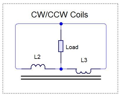


Of course, this is what I have found, and the Output Circuit is not limited to these Circuits specifically!

Look at the Independent Replications, for some inspiration:


  1. Bill Alek
  2. TinMan, Bradley Richard Atherton.
  3. Graham Gunderson.


Basic and up Front, No Bucking, then your machine does not work and you need to re-arrange your Machine.

This is an Asymmetrical Machine, all this I have covered here on my website. We have:

  1. Amplified Voltage. Turns Step up.
  2. Amplified Current. Bucking Magnetic Fields as in The Mr Preva Experiment.


For all we have covered, all of it, and if you've followed, then this task should be easy!

I Promise You, if you follow the rules, make your Machine do what I have said above and on my Websites, it will work. You will have an Above Unity Energy Machine! You have my word on it!

   Chris


NOTE: I expect you are experienced enough to competently work with Electrical Energy! This device can be dangerous, High Voltage and Current can very easily be achieved! I am not responsible for harm to person, and or equipment! I give you this very simple Guide as is and without warranty or guarantee. I have given a promise, and if you follow the instructions, this will work as I have stated! Making Changes will result in Failure.


Order By: Standard | Newest | Votes
Atti posted this 01 December 2018

   Hi. 

 I fully confirm Chris's writing!  Chris has perfectly summed up the building criteria, the opportunities to find work in the work of others.

 But!!

How much energy do I spend and how much can I get out of it? Are there any measurements in and out of this? How much is the difference?  Did anyone make a similar measurement? Just out of curiosity.

Chris posted this 01 December 2018

Hey Atti,

COP > 1.0 when one has Tuned Frequency and Duty. Also with good Gapping and any Switching.

Crazy thing is, many here could build for $20.00 and an hours work if they know what they are doing.

Again for the readers: Critical Point is, Partnered Output Coils MUST Buck, this is the Current Amplification part. Greater turns on the Output Coils steps up Voltage, this is Voltage Amplification.


Very simply: Power ( P ) = Voltage ( V ) x Current ( I )

   Chris


P.S: Lets see, what we see, from those that have waited for this for an eternity?

alohalaoha posted this 01 December 2018

   Hi. 

 I fully confirm Chris's writing!  Chris has perfectly summed up the building criteria, the opportunities to find work in the work of others.

 But!!

How much energy do I spend and how much can I get out of it? Are there any measurements in and out of this? How much is the difference?  Did anyone make a similar measurement? Just out of curiosity.


Hey Atti

It is not important how much input power you will inject in circuit 10Wt or 100Wt. You will get as much energy as you need at output once process was started.

Aboveunity power comes from charge injector pump, or from ferrite core charges.Sources of charges could be different. High potential - high frequency devices like Tesla transformer, Vladimir Brovin's Katchers (with HV bipolar or HV mosfets or IGBTs), Ground, Indepenent mass of high conductivity metals, salt water, highly ionised air, plasma sources etc.etc.

Charges only need to be sucked by Bucking Magnetic Fields and boost their initialy field strenght. Process is autosync once has achived. As low impendance is your load as much charge injecting would occur. This device make with easy infinite rise of power. So you need to sink additional power or to lower injection rate.

ps: The most important thing here is a TIMING. All must be balanced and coordinated. Maybe Chris should start with design electronic logic control for all kind of assymetric devices ?

Reg.

Aloha

alohalaoha posted this 01 December 2018

I want to share these Tesla's words which have a great importance to all aboveunity researchers and inventors.

They were from the lecture delivered by Nikola Tesla to the American Institute of Electrical Engineers at Columbia College, New York 20 May 1891. Lecture was firstly posted in the electrical engineer, a weekly journal of electrical engineering, volume viii, from 3 July, 1891.

Quote Tesla"

I would call attention to the fact, that in an alternating electrostatic field, a conductor, such as an exhausted tube for instance (or any resonant coil, waveguide, any conductor my addition), tends to take up most of the energy, whereas, in an electromagnetic alternating field the conductor tends to take up the least energy, the waves being reflected with but little loss. This is one reason why it is difficult to excite an exhausted tube, at a distance, by electromagnetic induction. I have wound coils of very large diameter and of many turns of wire, and connected a Geissler tube to the ends of the coil with the object of exciting the tube at a distance; but even with the powerful inductive effects producible by Leyden jar discharges, the tube could not be excited unless at a very small distance, although some judgment was used as to the dimensions of the coil. I have also found that even the most powerful Leyden jar discharges are capable of exciting only feeble luminous effects in a closed exhausted tube, and even these effects upon thorough examination I have been forced to consider of an electrostatic nature.  How, then, can we hope to produce the required effects at a distance by means of electromagnetic action, when even in the closest proximity to the source of disturbance, under the most advantageous conditions, we can excite but faint luminosity ? "

End of quote

Chris posted this 01 December 2018

Aloha,

This is a key Patent: TESLA PATENT 336,961 REGULATOR FOR DYNAMO-ELECTRIC MACHINES.

If, for instance, the commutator-space between the brushes a and c, when the latter is at the neutral point, is diminished, a current will flow from the point Y over the shunt C to the brush b, thus strengthening the current in the part M', and partly neutralizing the current in the part M; but if the space between the brushes a and c is increased, the current will flow over the auxiliary brush in an opposite direction, and the current in M will be strengthened, and in M' partly neutralized.


More than 100 Years old! dated March 2, 1886!

We already know this is specifically related to the Amplification of Current:


The Greatest man that ever lived, Nikola Tesla, the Mr Preva Experiment with Don's video, is undisputable.

   Chris

Jagau posted this 01 December 2018

I confirm what Chris quotes above for experimentation.

In my last experience with two coils partnered Output coils (POC) and one input coil  that transmits at the resonant frequency

with only 0.300 millivolt p/p, I got 60 volts p/p. Make yours you will see, easy and cheap to make.

It's reality.

Jagau


Jagau posted this 01 December 2018

The model to use is very simple Aloha, everyone can do it.
Take a pot core with 3 cables twister set of gauge 24 or what you have on hand, 2 cables are in mode P.O.C. and the third in Rx
With a signal generator injects about 5 volts p / p in order to
find the frequency of resonance when you have found injected into your POC and look at the exit you will be surprised at the result.
Adjust the voltage of the S.G. up to 300 mv p / p and you will still have a lot of voltage present. It is a (C.E). cold electricity, .but with an avramenko plug I turn on up to 5 leds without extra consumption.

P.O.C. configuration is the name of the game it is a must

Jagau

alohalaoha posted this 02 December 2018

Hey Jagau

What about current output? Have you did some meassurements ?

I need hundred of Amps at the output not some uA or mA. Also voltage must be in hundreds of volts not mV or V.

Need overunity heater to warm house and garage.

If you have concrete project let me know. Wish to bild one and improve if possible.

ps: I have not much possibilities to try thousands of experiments, simply because have no cash for all to realise. For all of this i need highly professonal and expensive lab and highend equipment and tools. This is only reason why do asking you and not only you but all the others for just one concrete working overunity device. Can make one but not thousands....

ps: my newest e-mail is sergvdrag@yandex.ru. Fell free to contact me if you have real ou device to share with me.

Thank you

Best regards to all - Aloha

  • Liked by
  • Jagau
  • ISLab
Jagau posted this 02 December 2018

Hello Aloha


I am in this forum to learn, and with my latest research I share with you the little things that I find

because this is the purpose of this forum.


share what would be interesting
learn to share it
help those whom we can help.


No I have not found the rosetta pearl yet but I'm working on it.

I hope I did not disappoint you, but you bring me ideas that sometimes move me forward.

Jagau

alohalaoha posted this 02 December 2018

Thank for your support and many clever ideas Jagau.

You are a good american man, in same free energy problems like all honest people in america.

If you belive in my words, same situdation is at russia, and very probably 99,9999% in other parts of the world.

I know from my life way , only experiement is a supreme judge of all possible and impossible theories because he always present and show us a truth. This is the only reason why we need to listen him and analyse what he always tell us. No other way in total darkness of this parasitic world.

Best wishes

Aloha

Jagau posted this 02 December 2018

hi aloha


I'm 100% agree with you, it's very good,
just do not let go we'll have it.

Just a clarification I am Canadian

Jagau

Chris posted this 02 December 2018

Hey Aloha,

Have you built the above layout I gave?

If so please post a picture.

Also, would you mind, please do not post material with my site addresses or my name that is not mine. What you posted above ( Now Removed ) is misleading for others. Its not my work, its yours. I hope you understand.

Thanks

   Chris

  • Liked by
  • ISLab
  • Augenblick
Chris posted this 02 December 2018

My Friends,

I would like to quote:

Useful energy occurs as the result of imbalances in the ambient background energy, which is a transient phenomena. In the electrical field, it is a closed system subject to heat death, which severely limits it's utility. The flip side of the electron, produces magnetic waves which are an open system, not subject to heat death. These waves, being unrestricted, are the universal source of energy when unlimited resonate duplicates from this one source are available. Therefore, the key to unlimited energy, is Magnetic Resonance. In order to understand this, requires putting a stake through the Heart of Antique Physics. Non-linear and Open Systems are universally available in Magnetic Resonance Systems, Explosions of any sort [including Atomic Explosions] and Combustibles of any type. Mechanical equivalents would be levers, pulleys and hydraulics. A highly obvious example is the Piano where the Key impacts the one note giving one sound level, which resonates with it's two side keys providing a much higher sound level. Magnetic Resonance Energy clearly amplifies itself, demonstrating more energy out, than in.

Ohmic resistance does not apply to Magnetic Resonance which travels unrestricted for great distances, therefore multitudes of electrons are disturbed, and their back-spin translates magnetic into usable electric energy. The right angle component which the magnetic flux provides, translates into useful electrical energy. Taken at right angles, the Magnetic Dipole provides an unlimited source of electrical energy.

Don Smith - Resonant Energy Systems


Don't forget what we learnt in The Mr Preva Experiment! Magnetic Resonance, we know what it is already and already achieved it! We must get the voltage up, and this is how you do it!

Monitor your Currents! Like I showed you in the thread: Some Coils Buck and some Coils Dont

The Frequency and Duty you need to find, I believe you will find, is a harmonic of the Partnered Output Coils natural Resonant Frequency - Now I have said to much!

Now the Numpty Club will beat us to the Gold Nugget. Comon people, we have to be first!

   Chris


Vidura posted this 02 December 2018

Chris, Check the schematic s you posted in the beginning of the thread. For opposed like magnetic poles the load should be connected to the center tap with CW/CW coils (eventually con diodes) and at the ends between two coils for CW/CCW coils. Regards Vidura

Chris posted this 02 December 2018

Hi Vidura,

Yes, many output circuits can be arranged. Yes Diodes can be of benefit. Also other conduction circuitry.

The Circuits I posted are a guide and depends on the Partnered Output Coils and how they are arranged. I published this circuits some 4 odd years ago now. Without looking it up exactly.

Yes, the Center Tap can also be used.

Really, the point is, the Partnered Output Coils must Buck and also produce usable Electrical Energy.

  • Two Output Coils - Must.
  • Electrical Energy - Must

For example, a single output coil will never work.

How's progress Vidura?

   Chris

  • Liked by
  • ISLab
  • Augenblick
alohalaoha posted this 03 December 2018


You Will need:

  1. One Input Coil
  2. Two Output Coils
  3. Patience
  4. Support


You need to follow the basic plan laid out here:


NOTE: Partnered Output Coils can be wound either CW / CCW or CW / CW Flipped.

  • CW is Clockwise.
  • CCW is Counter Clockwise.


I prefer CW / CCW.

You will need to make sure your Output Coils have Opposing Magnetic Fields, thus Opposing Currents! 


This is a Critical and Required Component!


The Operation to start with is as follows:

  1. Input Coil ( Green Coil ) brings up the Potential, then is switched Off.
  2. One Output Coil then Conducts Current ( Gold Coils ).
  3. The Second Output Coil then also conducts Current, a split second after the first, Equal and Opposite, to the First Output Coil ( Gold Coils ).


Chris

Hey Chris

If you think it's needed for all members here rearrange your picture according to Donald Smith reference. He had told - RIGHT WOUNDED SPIRAL (CW) MADE CURRENT or precise CHARGES MOVEMENT FROM + TO -, LEFT WOUNDED SPITAL (CCW) MADE VOLTAGE or precise CHARGES MOVEMENT FROM - TO +.

Lenght of CW wire bring us CURRENT RESONANCE, lenght of CCW bring us VOLTAGE RESONANCE.

What are in fact bucking coils or better formulation PARTENRED COILS ?

We simply obtain RESONANCE IN RESONANCE !!

However geometry of excitation coil is very important in respect to output partnered coils. Any advice here ?

Also type of excitation envelope, sinus, cosinus, triangle, square, nano-pulse, pulse trains or some mixed envelope ? Any advice here ?

Excitation on lambda resonance or lamba/4 resonance ? Or on free LC resonance, or on geometric mean of two LC resonances if we have full asymmetric configuration for example CW{C1=1nf}, CCW{C2=100nf}. Or maybe is best to tune free LC resonance to intersection point with Standing Wave Resonance ?

If somebody can explain, will be excellent reference for all people here.

ps: Chris i dont like this simple fact. From 163 members only members you can count on your fingers make posts and share experience and knowledge, other 153 simply STEAL HARD WORK OF those 10. I think it is very very bad !!!! That way went alsways to blind-alley. !!!!!!!!!!!!

Reg.

Aloha


Chris posted this 03 December 2018

Hi Aloha,

I think, think Simple.

Follow the first post, don't change anything, make the goals and there will be no confusion.

Yes, we do have a small few here, waiting to thieve the good bits.

He shot out of here like a scolded cat when he saw the thread I left him!

Note: Some members here, English is not their first language, and they wish to stay quiet readers. They would never have trouble here! But I understand their position.

   Chris

alohalaoha posted this 03 December 2018

Hey Chris it is Ok my friend.

I knew you have told all the truth about partnered coils. I knew man called himself on one russian free energy forum Tank who first said MR.Preva how to make current boost. Btw I don't know Mr.Preva personaly and its not important.

All my thoughts are about the role of electrostatic field here. As many time has went i am prety sure that partnered phenomenon has electrostatic nature, nor electric, nor magnetic, nor electromagnetic !! As great Tesla once said "Pulsation of charges".

Remember Donald's board, why he had used HF HV electrostatic field ?

ps: I should repair my two oscillographs C-112A and PM3208. Simple rule: There is no free (not lunch) but experiment !

Free lunch could be at many places, but free experiment nowhere !

Regards

Aloha 

  • Liked by
  • Chris
  • Augenblick
Chris posted this 03 December 2018

Hey Aloha,

I have read many of Tanks posts.

Yes, one path forward, experiment, is knowledge gained for repeatability. Of course this is except for Brad, he can no longer make a machine work. Thus the reason he comes here.

@All - Keep in mind the very important concepts we have covered!

I have given a few hints on this thread!

There is no Wrong or Right, there are many ways this works!

   Chris


Chris posted this 03 December 2018

My Friends,

I kept the term "Magnetic Resonance" for many reasons. But most of all, Floyd Sweet used it, Don Smith used it. Others have used it.

Before to long Bradley will no doubt use it. He was last here, reading our pages yesterday.

I would recommend you adopt it also if you haven't already.

Now, a small tip, I mentioned the Partnered Output Coil time delay, or offset. Many ways to achieve it, but how did Don Smith do it? Three hints here on this Thread about it now!

Remember, Partnered Output Coils must Buck, Currents and Fields must oppose. Monitor your Current!

   Chris

Vidura posted this 03 December 2018

Hi Chris
Yesterday I have lost a detailed post, so i have to edit in another program and paste.Maybe i should have formulated my last post as a question, i am aware that you have tested this for many years. So yesterday i had made some experiments using your guidelines , where i tried different configurations, like in the posted schematics and reversed with and without airgap, diodes and so on. I found it actually easier to get a significant output connecting the way like in the schematic, but using the right hand rule the fields are not opposed like poles. Neither they are in the Mr Preva experiment, in this cases the fields are allowed to align as unlike poles, and they are forcing the current to flow from the lower to the higher potential side. In my test setup i got this way a exponential current curve, not a sawtooth. With a airgap the interaction least much longer. Also the diode helps in this case, without it the pulses become very short and sharp, and the input power increases.

Anyway i think the diode is not strictly necessary when the coils are tuned correctly in resonance. When connected the other way , so that fields are forced for opposing like poles there is a very notable reduced impedance as expected, but i still could not get out a significant power level on the output. The spikes are very sharp and short and don't make lit a bulb. This could be due the small nr of turns of the coils, so i rewound one with more turns-more inductance, which i still have not tested. Regarding your question: thanks for asking, sincerely i have not much progress lately. Maybe due to problems in daily live I hardly can concentrate well in the investigations. Such is life sometimes , then it will change for better again certainly.

Vidura.

alohalaoha posted this 03 December 2018

Hey Vidura

On which frequency you have pulsed your partnere coils ? Free LC resonance or something different ?

Reg.

Aloha

Vidura posted this 03 December 2018

In this setup i sweeped frequency from 180hz to 700hz. 1 —2% duty without capacitor attached.at lower frequency ther was better output power.

alohalaoha posted this 03 December 2018

Setup was like Chris have done or you have changed something ?

How many windings you have wound for CW/CCW coils?

Regards

Aloha


Chris posted this 03 December 2018

Hi Vidura,

Sorry about the loss of your post. The session of your login timed out. There is an App Pool issue I am still trying to resolve.

My life is full at the moment also, problems unexpected. You're right, better it can only get.

-------------------------------------------------------------------------------------------------------------------------------------------

Yes, Yes, the exponential curve is right, that's good!

Voltage will be the Sawtooth wave, it is a linear reduction, fall to zero, due to the opposing Currents.

Diode is good, it creates a delay, ever so small, some are in the nanoseconds, but it can be enough in some situations.

You could always load each coil separately?

The same result will occur.

Also, sometimes, stay safe doing so, but increase input voltage just a little. 

Excellent Vidura! You're on the right track! Like the Mr Preva Experiment, there is no difference except we are using a low impedance Coil to drive this arrangement to increase Voltage, to test the result, hook the Coils in Series and see if the Current has doubled? If not, the Currents are not Bucking. 


This was the device that I shared with everyone here: Bucking Experiment Way back on April 16, 2014


It was the next step, driving with a separate Coil. Sorry for the mess in the video. It was a very busy day.

Remember where Floyd Sweet started:


The BIG sponge trying to damp vibrations!

Remember, we must have Bucking. At the right power level, with cores, you should hear or feel a definite vibration!

   Chris

Zanzal posted this 03 December 2018

My Friends,

I kept the term "Magnetic Resonance" for many reasons. But most of all, Floyd Sweet used it, Don Smith used it. Others have used it.

Hey Chris, I wish I understood what you meant by this, but I am finding it elusive. From your scope shot, you use a single current pulse to trigger a double current pulse. The single DC pulse, results in a non-sinusoidal wave that is effectively two current pulses travelling against each other but the second one is staggered (out of phase).

By magnetic resonance, you just mean that the two pulses do not occur simultaneously, that the reverse pulse is delayed or do you mean something else?

The term "magnetic resonance" in this context just means "staggered so that you get two distinct pulses instead of one?" So its as if you made a transformer that receives a single phase and produces two equal phases of output, but only when it is 1) driven at the correct frequency (as determined by ???) and 2) that the second coil is loosely coupled so as to not to load the primary.

If I am understanding for this to work each pulse must carry the same energy as the total input pulse or somewhat less with losses, but the second pulse as your additional energy. Honestly I am surprised this system doesn't generate reducing oscillations, the system looks from the scope shot to be self-damped... Sorry in advance if none of these questions are coherent, I'm trying to establish a theory of operation which unfortunately, may only make sense to me...

  • Liked by
  • Chris
  • Augenblick
Chris posted this 03 December 2018

Hey Zanzal,

Apologies, I wish to be direct, not rude.


Magnetic Resonance:

Magnetic Resonance is where the Currents in both Partnered Output Coils are 180 degrees out of phase. Equal in magnitude and opposite.


We learnt this in The Mr Preva Experiment.


The Coils must Buck each other. There is no complication to the operation, but is some fiddling to the optimum output.

We have thieves that visit us, we must be careful to avoid putting to much information out. If people have read what I have laid out on my pages, done the experiments as I have laid out, there is zero complication to this.

We have had Above Unity Machines for a long time, I am not the first person. But I am the first person ever, to show you, how to do it.

I have laid out, very carefully, a path of discovery.

It only need be followed.

   Chris

Chris posted this 03 December 2018

My Friends,

Listen carefully, what do you hear?


   Chris

Jagau posted this 04 December 2018

Hi Chris

Yes we hear a strong vibration

Jagau

Chris posted this 04 December 2018

@All,

Start small FIRST! Learn the workings First! As Vidura has.

Remember, the Core material can hold only so much flux.

Increasing the Core Size, the Cross Sectional Area, CSA, increases the Flux carrying capabilities.

You need to lower, to decrease, the turns as you go up in Core CSA. Of course, thicker wire may be required also.

   Chris


Please be careful, this is very dangerous as you move up in size.

Atti posted this 04 December 2018

"Remember, the Core material can hold only so much flux.

Increasing the Core Size, the Cross Sectional Area, CSA, increases the Flux carrying capabilities"


Chris,  With the above statements I completely agree, but! This is true. I have tried some layouts already. But the question is still open:

-what is the input power requirement?

-what is the output power requirement?


In some variations I tried and measured the Mr Preva layout.

Has anyone weighed curiosity?  Not the amper but the power. (P = UxIxcos fí )  output power/input power.

Chris posted this 04 December 2018

Hey Atti,

Sorry, all I wish to say on measurements is Output > Input with some work.

The Mr Preva Experiment as it stands, is Input > Output. It must be changed accordingly.

I would say, it is entirely up to the experimenter as to weather they post Measurements.

To  prevent the circling of vultures, I recommend keeping some information quiet. we do not want people here that are not genuine, here to thieve our hard work.

For, all humanity can not benefit, if the top 1% have everything!

   Chris

  • Liked by
  • ISLab
  • Augenblick
Atti posted this 04 December 2018

 "Do some information remain silent? "


let it be ...............................

  • Liked by
  • ISLab
  • Augenblick
Chris posted this 04 December 2018

Hi Atti,

The choice is yours. You can post if you want to.

Posting negative material toward others will not help. We are learning. Dont make judgment.

   Chris

Atti posted this 05 December 2018

Do not misunderstand Chris !! I do not want to deny her work! It has invested immense energy in these experiments, which I fully reaffirm. As can be seen in shared videos.
But energy balance is a bit different. Yes, obviously it is not a good idea for others to share information with fars because they are misleading.
So I do not judge just sharing my helpful opinion. Please understand that.

Chris posted this 05 December 2018

Hi Atti,

Understand, and thank you. 

Energy balance comes with a set of circumstances, extra effects will be seen, but only at a specific point in the interactions of the two Partnered Output Coils.

Magnetic Field magnitude plays a role. Frequency and Duty Cycle play a role. Timing plays a role.

There must be a specific point where input is off, and Partnered Output Coils have a Magnetic Resonance occurring.

This Magnetic Resonance is where extra Energy comes from. Bucking Magnetic Fields.

When Current in one Partnered Output Coil has reached a point where it is at its maximum, the second Partnered Output Coil must then Conduct, this creates the opposing Magnetic Field, the Current doubles as a response of the Bucking, the same as we saw in The Mr Preva Experiment. Currents equal and Opposite, 180 degrees out of phase.

Remember what Floyd Sweet said:


In the specific case of positive charges moving to the right and negative charges to the left, the effect of both actions is positive charge moving to the right.

Current to the right is: I = da+ / dt + da- / dt.


Negative electrons flowing to the left contribute to the current flowing to the right.


I ask, we are learning, so please, let us not make judgement on others work! We must nurture and guide the progress, of those that are working hard to learn. Lets respect each other as we would expect for ourselves. I am generalising, for all here.

   Chris

Chris posted this 07 December 2018

My Friends,

When you get the Required Bucking of the Partnered Output Coils, an effect like is shown in the following video:


You will see, once the point is reached, a greater Bucking, louder noise, is reached. At this point you have maximum output. This action is entirely an Interaction between the Partnered Output Coils. 

I showed this here:


The Input is reduced, because we have an additive Magnetic Field.

   Chris

alohalaoha posted this 07 December 2018

Self Resonance in Coils


Attached Files

  • Liked by
  • Chris
  • Augenblick
Chris posted this 07 December 2018

My Friends,

Aloha is exactly right! Often an Earth Ground may be needed.

   Chris

alohalaoha posted this 07 December 2018

Quadrature Bucking Coils  = Self Running Motor - based on Tesla patent 511916 titled as Electric Generator by Tesla

Chris posted this 07 December 2018

My Friends,

Aloha is correct, however the Four Coil Structure is not necessary. The same effect is present.

I would ask, keep it simple, low frequency, a small pulse can give a large result.

   Chris

Chris posted this 08 December 2018

My Friends,

A long time ago, I shared a bit of work, it holds relevance today: What's it going to take to Get OU?  ( Date Created: 10/01/2014 1:10:58 PM )

It is true, what I started working on then, although not worded perfectly, it does outline the basics. It turned out, the reference to introducing an Iron Core, is simply Bucking Coils at the right time! I also shared that in my initial release of Partnered Output Coils.

This is simply the: Reduced Impedance Effect.

We have all the answers! Its just a case of getting the right order of the answers in our heads.

   Chris

Jagau posted this 09 December 2018

You're full of resource Chris


I reread your article, very explicit that all should read, excellent. 


What's it going to take to Get OU?


Jagau

Chris posted this 09 December 2018

Thanks Jagau!

Those that read these pages will notice some similarity in the ideas presented. There is some base level items presented in the 'What's it going to take to get OU' that we have seen in other devices.

Graham Gunderson used Permanent Magnets to try to Bias the Core of his MIT to get up to close to the Knee of the BH Curve, Ironically, I used this requirement in my document. Ironically, Bucking Coils I have been presenting for many years, since 2011, Graham Gunderson used Bucking Coils.

Thanks to Reiyuki


Graham deserves full credit, he did an awesome job, and an awesome demonstration! I could not have ever done such a professional demonstration. Even though he did use all my work. Only a few years earlier, stating he did not look into interactions of Coils and had only investigated Floyd Sweets Permanent Magnet Conditioning, which was a Hoax and a Lie.

Yes I have had some communications with Graham and his team members over the years. I did share Floyd Sweets Transcribed Lab Notes with the Aseop Institute and we had some communications as a result. All readers should research this story.

Mark Goldes never released any documentation on Floyd Sweet. I asked a few times, he told me he had none.

Graham Gunderson worked for Mark Goldes for many years.

Mark Goldes had on the order of 50 companies, all going either bankrupt or closing. Companies including: ASEOP, MPI, Chava… and others. Mark Goldes, then ASEOP Institute, funded Floyd Sweet, some of the equipment in images of Floyd Sweets demonstrations was funded by Mark Goldes, but not all:

Mark Goldes, Co-founder of Chava Energy and Chairman of Magnetic Power Inc. and its synergistic subsidiary company, Room Temperature Superconductors Inc. Chava is acquiring assets of both the earlier firms.


Magnetic Power Inc. Company assets are being acquired by Chava Energy. The new website is http://www.chavaenergy.com/ Devices formerly called Magnetic Power Modules(tm)are now called MagGen(tm).

Chava is developing these modules as well as other breakthrough technologies.

As of the Summer of 2009, Mark Goldes claims to have achieved several over-unity protypes, and hopes to have commercial 1 kW units ready next year. The company claims that those with an EE background and with an open mind will agree that the concept (disclosed under NDA) is workable.

For those who do not have access to proprietary photos, videos, and other evidence due to the proprietary nature of this technology, confidence is borrowed from CEO, Mark Goldes' reputation with Ultraconductors, a known and proven technology.


Some well known names worked for Mark Goldes:

  • Cyril Smith ( Smudge )
  • Partzman
  • Graham Gunderson
  • Others I cant think of at the moment.


If my research is correct, Mark Goldes never once produced any Product, no Product ever went to market.

Suppression comes in many forms, sometimes suppression of technologies, appears in the form of business Failures. Those working for the System, not realising they are part of the problem.

Note: Almost every page out on the Internet, when Searching Mark Goldes, contains the word: "Swindle". Mark Goldes has earned a somewhat dubious reputation.

   Chris


Jagau posted this 09 December 2018

Thank Chris for sharing those information

We understand better now.


Jagau

cheors posted this 09 December 2018

Chris,

I am new here and english is not my native language.

Could explain (once more probably) what "buck" means when you say "coils must buck, a bucking oscillator" ?


  • Liked by
  • Chris
  • Augenblick
Chris posted this 09 December 2018

Hi Cheors,

Welcome!

Buck means to Oppose Magnetically, and as a result, the Current from one Coil to the next must also Oppose, or run in the other direction.


The following experiment shows the meaning:


   Chris

  • Liked by
  • ISLab
  • Augenblick
cheors posted this 09 December 2018

OK thanks, i understand.

In that video, the 12V source is not disconnected, so we don't see the self sustain aspect.

But we get 5.2 A output and 2.8 A input : not so bad !!!

When i have time i will try something like that.


Chris posted this 09 December 2018

Hi Cheors,

The Mr Preva Experiment is a learning tool. It is not a self running Energy machine. It is very valuable experiment to replicate.

To Double Voltage from V to 2 V, and also double Current from I to 2 I means a total Power increase of 2 P from P.

We know how to achieve both methods.

   Chris

  • Liked by
  • ISLab
  • Augenblick
Atti posted this 10 December 2018

Hello everyone.

cheors. It's best to study your own small experiments. Just as Chris suggested it. Look at the work of others, then compare it with yours. Finally, withdraw your own conclusions from it. You can learn from everything, even from a bad experiment. It's really good if you can look at other work but do not replace yours. Mr Preva's experiment is very useful, but not mixed with your partner's output coils.

Observe winding directions. Now let's look at a magnetic test. 

I've already done some research on this topic. 

It can be seen that induction is induced by higher inductance. Do not expect a miracle from him, but keep in mind! This is a good game, I recommend it to you as well. If you like to share the results with us.

We're Light Years Ahead!
Members Online:

No one online at the moment


What is a Scalar:

In physics, scalars are physical quantities that are unaffected by changes to a vector space basis. Scalars are often accompanied by units of measurement, as in "10 cm". Examples of scalar quantities are mass, distance, charge, volume, time, speed, and the magnitude of physical vectors in general.

You need to forget the Non-Sense that some spout with out knowing the actual Definition of the word Scalar! Some people talk absolute Bull Sh*t!

The pressure P in the formula P = pgh, pgh is a scalar that tells you the amount of this squashing force per unit area in a fluid.

A Scalar, having both direction and magnitude, can be anything! The Magnetic Field, a Charge moving, yet some Numb Nuts think it means Magic Science!

Message from God:

Hello my children. This is Yahweh, the one true Lord. You have found creation's secret. Now share it peacefully with the world.

Ref: Message from God written inside the Human Genome

God be in my head, and in my thinking.

God be in my eyes, and in my looking.

God be in my mouth, and in my speaking.

Oh, God be in my heart, and in my understanding.

Your Support:

More than anything else, your contributions to this forum are most important! We are trying to actively get all visitors involved, but we do only have a few main contributors, which are very much appreciated! If you would like to see more pages with more detailed experiments and answers, perhaps a contribution of another type maybe possible:

PayPal De-Platformed me!

They REFUSE to tell me why!

We now use Wise!

Donate
Use E-Mail: Chris at aboveunity.com

The content I am sharing is not only unique, but is changing the world as we know it! Please Support Us!

Thank You So Much!

Weeks High Earners:
The great Nikola Tesla:

Ere many generations pass, our machinery will be driven by a power obtainable at any point of the universe. This idea is not novel. Men have been led to it long ago by instinct or reason. It has been expressed in many ways, and in many places, in the history of old and new. We find it in the delightful myth of Antheus, who drives power from the earth; we find it among the subtle speculations of one of your splendid mathematicians, and in many hints and statements of thinkers of the present time. Throughout space there is energy. Is this energy static or kinetic? If static, our hopes are in vain; if kinetic - and this we know it is for certain - then it is a mere question of time when men will succeed in attaching their machinery to the very wheelwork of nature.

Experiments With Alternate Currents Of High Potential And High Frequency (February 1892).

Close