electrondiger
posted this
15 October 2022
- Last edited 15 October 2022
Hy
wow i realy didnt know that Don smith Device is under replication atempt. Realy nice.
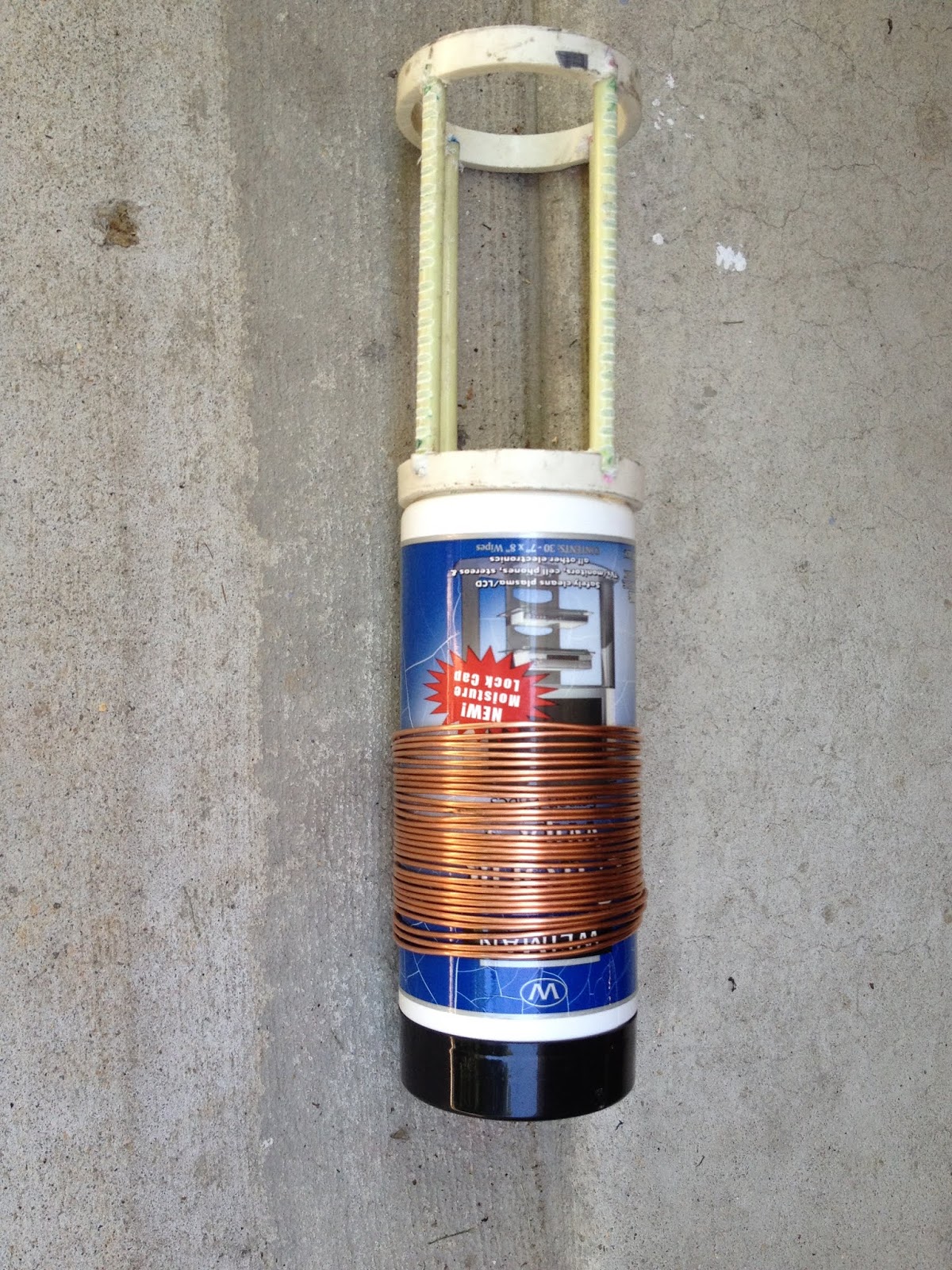
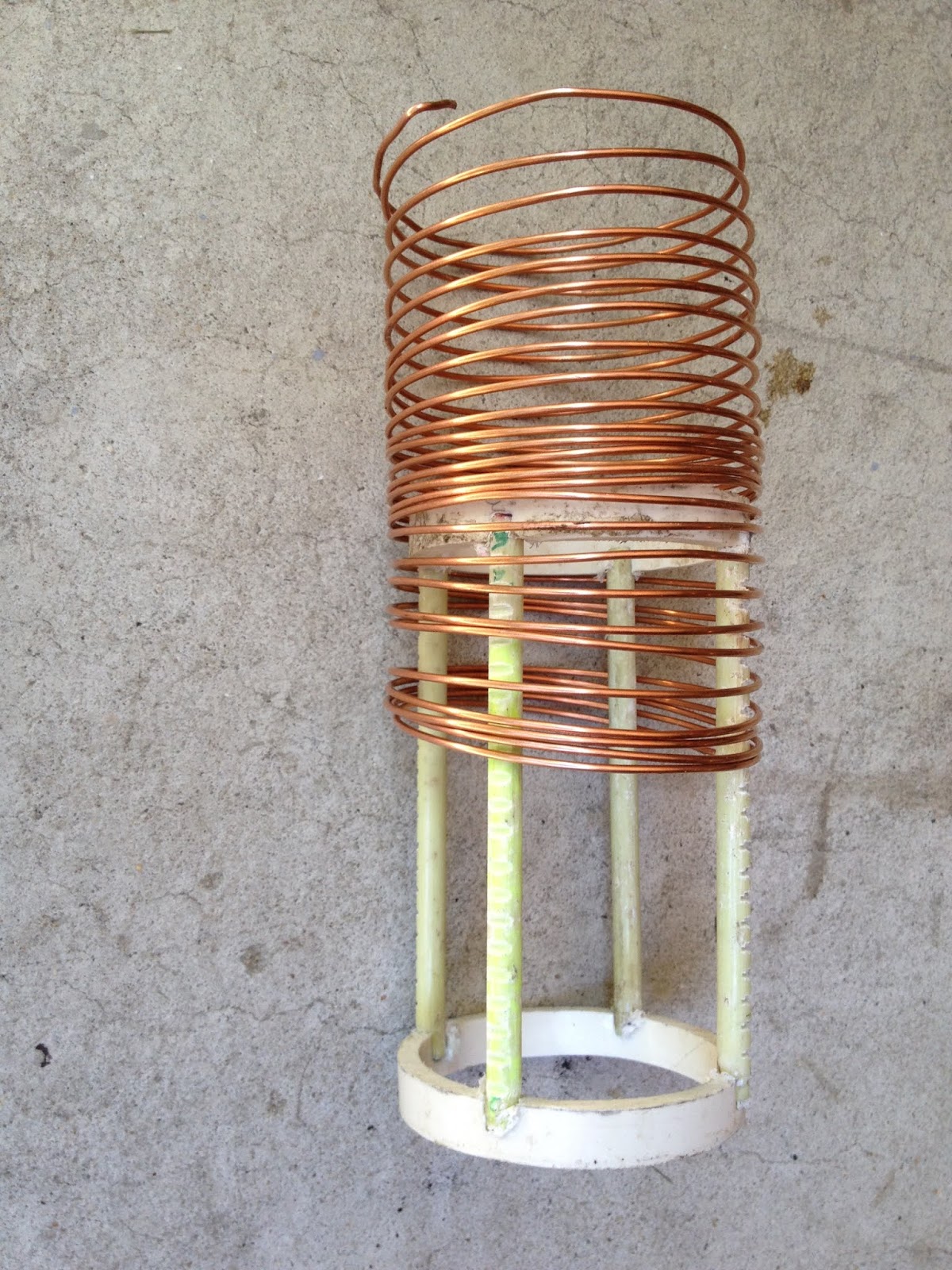
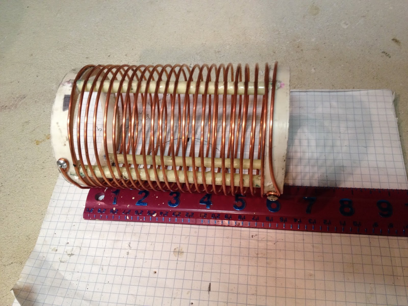
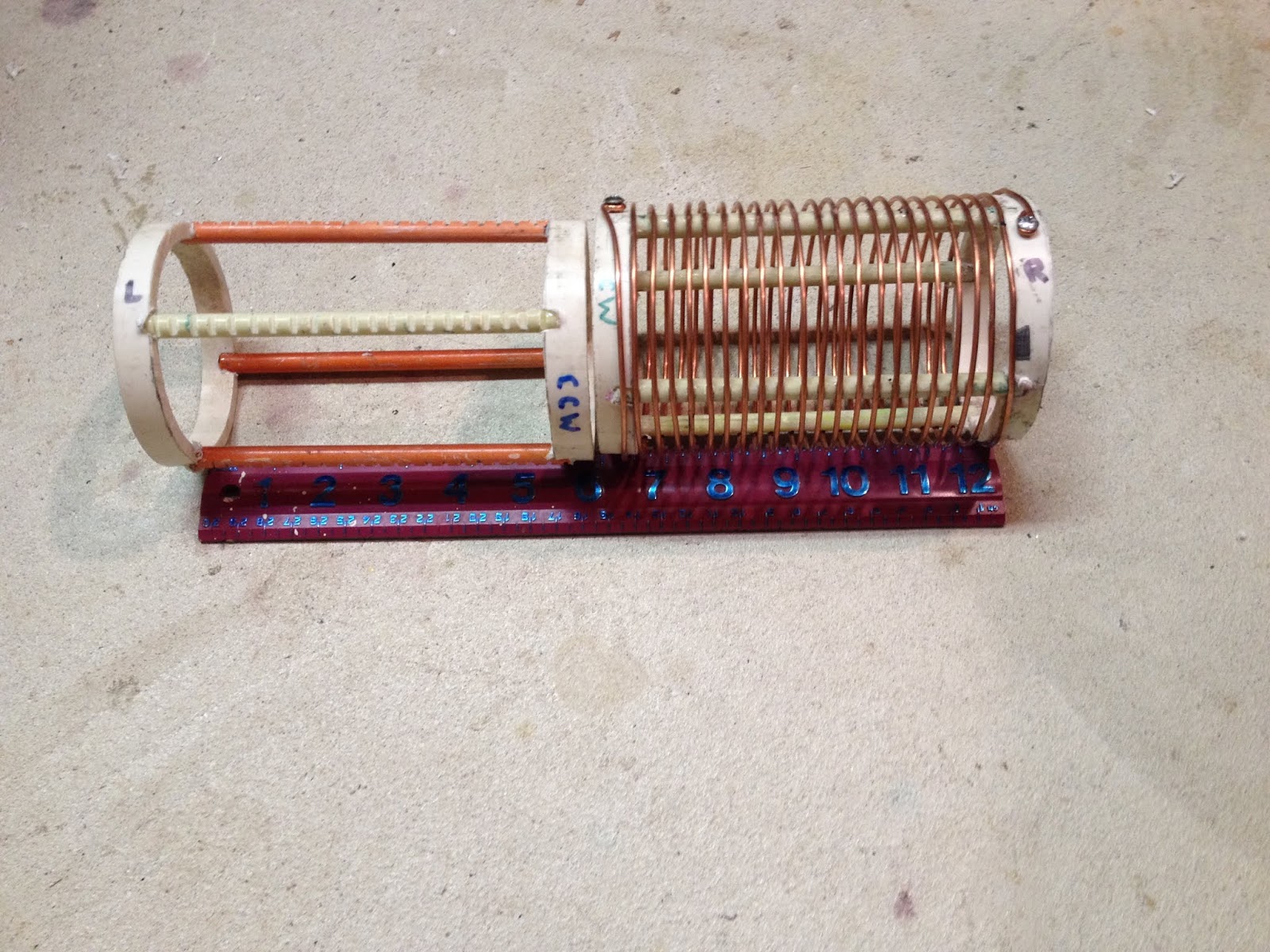
If i can ask, ( it is realy stupid question perhaps), but i have realy pain in the ass with it for several years. If you look that coil of Don there are some sort of strips to hold turns together. Where can you get those or how you can make it. i will not go in detail what i have tryed alredy. If somone has some sort of ideas woud be realy an eye opener. I didnt find them on the web.
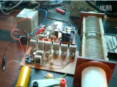
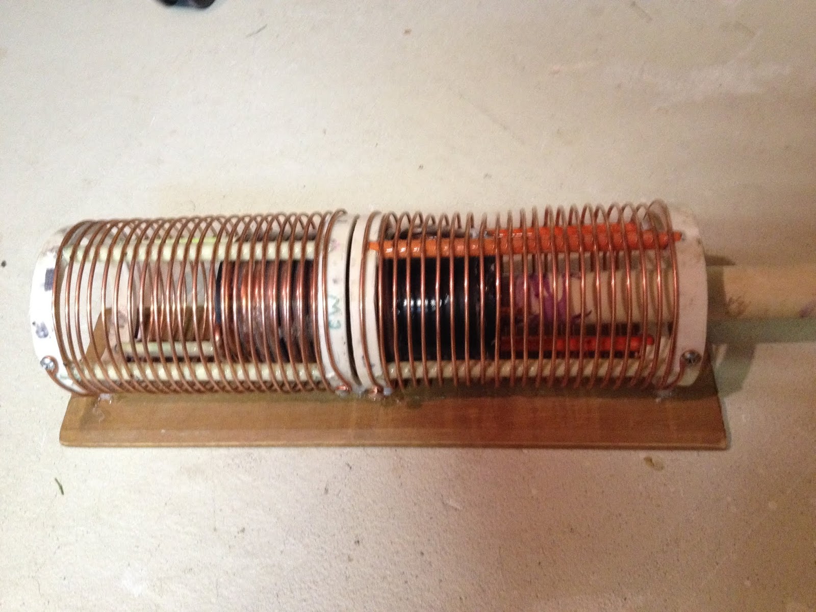
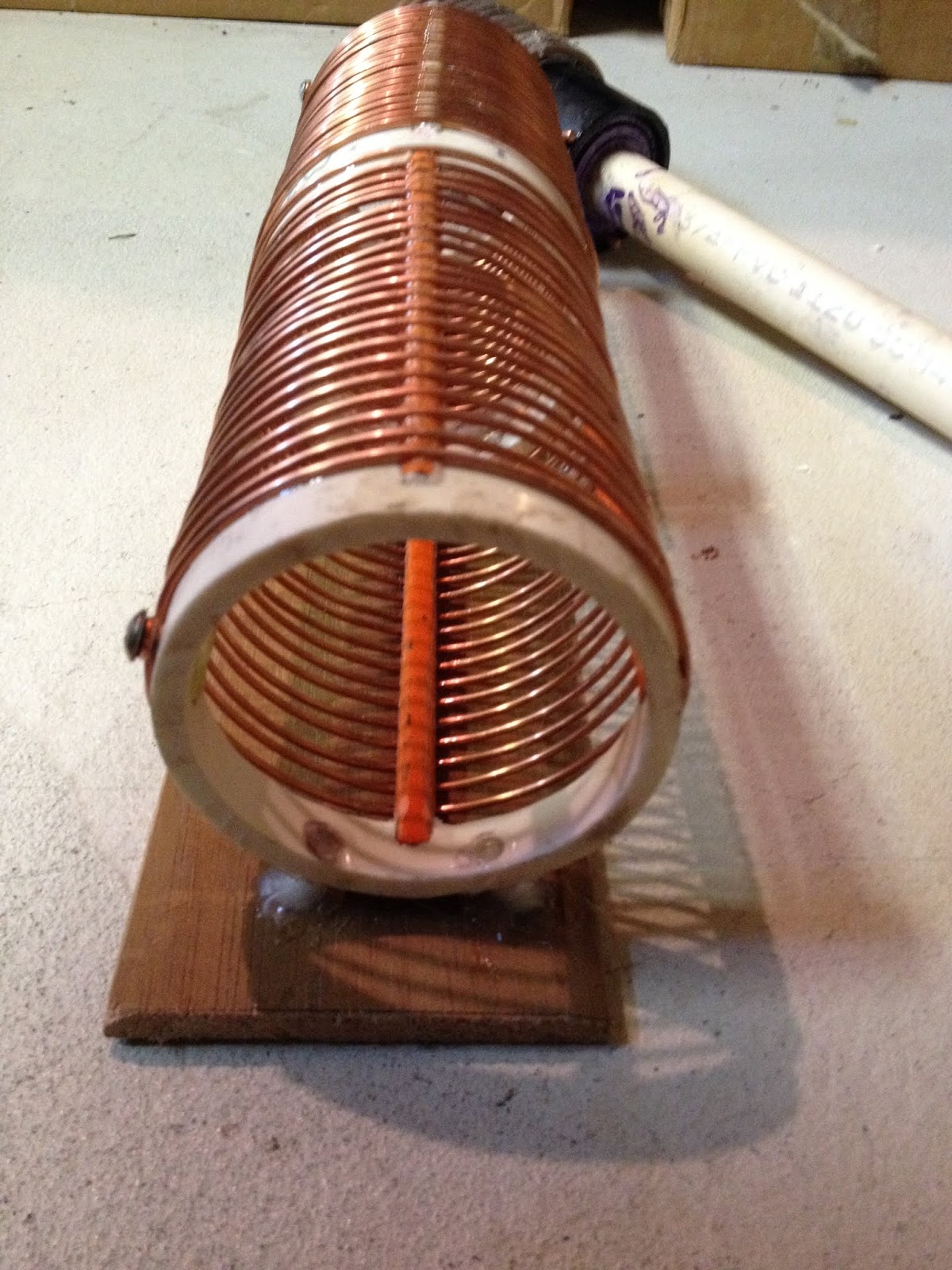
Coils are from B&W
If i understand corectly, coils have dimensions spacing ( i think that D/space betwen turns=0.6 best) and so on. Dons are D/space =1. If i understand corectly best coil lenghts is 0.8 of its diameter becose of eletric properties, but Dons is longer. I read somwhere that lenght give you voltage, diameter give you amperage. Coils are grounded in the midle so maximum voltage is at its ends. And if i corectly remember you need to find node in the midle with the neon bulb and make ground conectinon directly in the node. So dont buy wire for winding motors. Buy isolation wire and strip it. L2 is from 2 parts this is thrue. L1 must be multistrand wire, why. Low R and so on. When you kik you kik hard.
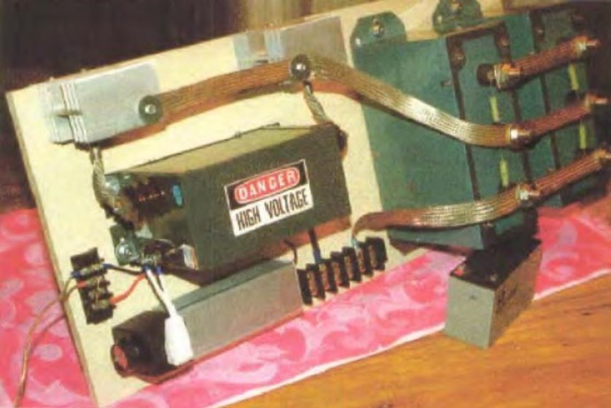
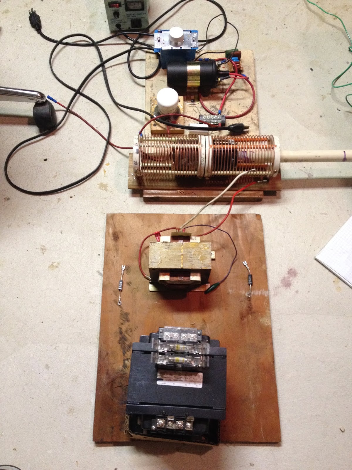
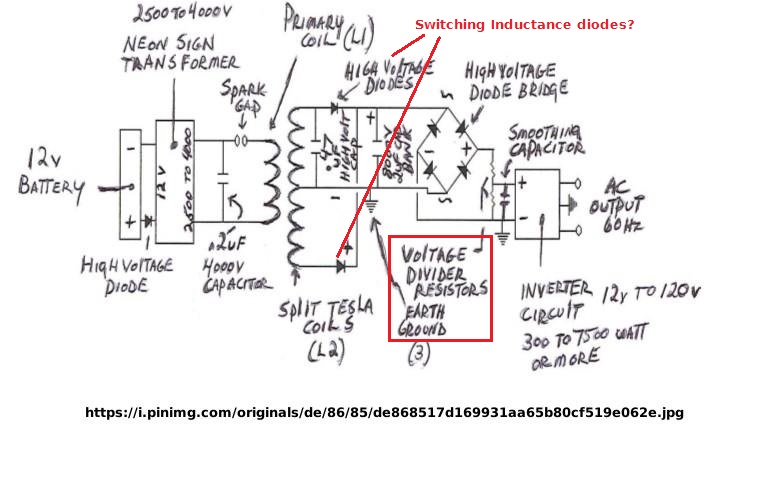
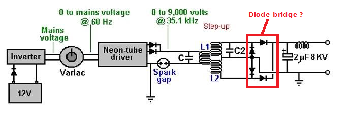
em,... i think that HVM - high voltage module or neon transformer in this device was tempered with. There was lots of talk about this on forums. If you choose neon transformer there is a problem with frequency. It is only 50 Hz. So you are left to the stuf down the line ( elements afect your frequency). If you buy eletric neon transfomer or HVM from american company Ventex, you will noticed that they havee difrent models. But company murged with other company. If you call theirs rep they will told you cant buy Don Smith HVM eny more. They dont prduce it eny more. If you have fix frequency in HVM they frequency is inposed on elements down the line. ( i didnt mesure this ).
Spark will not fire when you conect coil you need to modifiy it this was also "the problem". And high frequency diodes with high amp are pricey. High voltage capacitor too, so dont go over 20Kv.
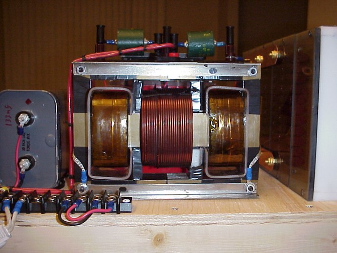
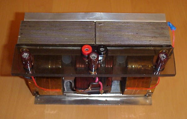
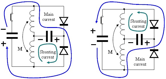
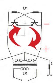
I think that in scheme there is only half the circuit, and that somthing is in last transformer too, how it is made. There shoud flow another kind of curent in there. This curent in primary gives rise to ordinary curent in secondary. This is the reason why you need big wire on secondary but you can have smal diameter wire in primary. There was talk that diodes was turn bakwards too. One pole( +,-) of electricity you must push to ground so you get another pol (+,-) on the winding of primary on last transformer. And this will realy run your secondary and your load.
What i have writen here is from reading from all directions over the internet. If it helps ok if it dont please delete.
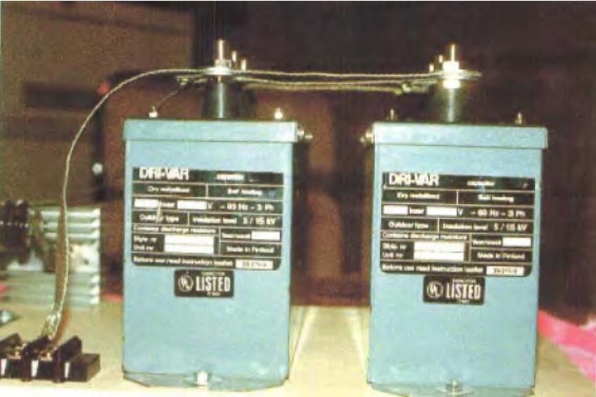
One more thing. Don said that he god some caps from compenies only on big orthers. This is not true. Soome original stuf from pictures was bought from ordinary suply stores. Parts witch are produce in large quantities and are on sale everywere. But is thrue Dubuise company. You can orther caps in this company they do custom orther for inventors. And if i read this wright some years back, you can get fre samples.
Perhaps .. ok. If i lok at tesla coil and what Tesla did. I think that he took induction law and use it brutaly with capacitors. So. Dc curent from dinamo over the spark gap and soo on. Dc high tension in capacitor. This is Voltage i think. Over the spark gap. Caps discharge realy quicly you need multistrand wire for this and as smal number of turns. There are pictures of one turn on tesla transformers. Look it up. Em,.. and no curent overt the gap. Magnetic quenching and air quenching, series spark gaps and so on. I think Tesla wonted to play with energy not electrons. Becose ... ( this is wierd one),... electrons dont exist if you read some books. Then was a fight about electron, some founders of electricity said that if you think there is an electron you are stupid or delusunal. And electron dont travel fast they are realy slow. Energy travel fast, rely fast. I think tesla try to separete electrons from energy and play with energy. Electron exist in modern science. Thompson and so on.... . I know dont kill me. They made a picture of it. But electron is some sort of braking mechanisem from space energy when starts to brake down to lower velocities and material world. And if you reed some books they say that material word particles are yumping from conterspace to this space so fast you cant see them. huh,... if you look some exsperiments from water. You will found that tehre are exsperiments in water with cavitation witchproduce metal particles. They made ingot from them. I am not smart yust saying it is wierd stuf when you go some steps to rabit hole.
( Chris if there is some stupid stuf in this post yust delet it)
Have fun.


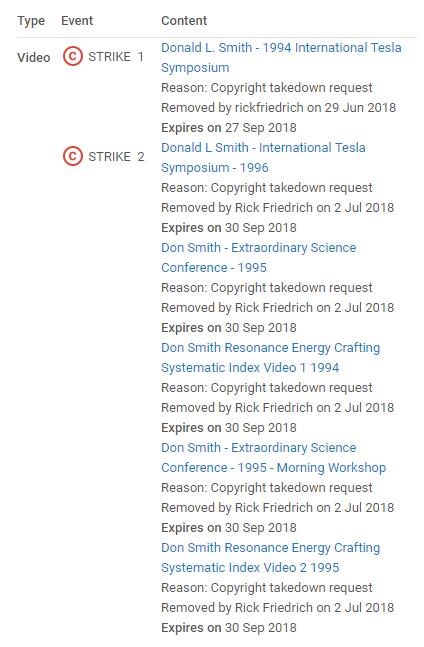
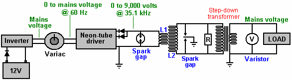
 And would definitely also like to thank MrBlobby for making it possible for others to see these gems. They are priceless, especially the 1994 video that provides more info on the ground resistor shunt and its connection to rising waveform - the thing that Don didn't talk about much on Yahoo Group and newer conference videos, only giving generic descriptions like "proper grounding", "adjustable grounding" etc.