

Hi everyone.
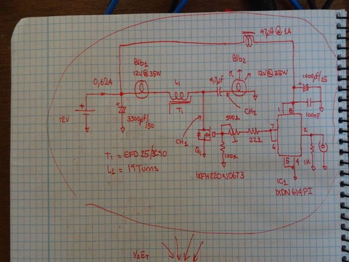
Circuit to check ferro-resonance.
The two bulbs are 12V @ 35Watts, if you want you can do the experiment.
The mosfet can be an IRF3205, anyone with an Rds (on) whose value is at least
the value of the load between 10 so that Norton is negligible.
For example, if the bulb is 35W @ 12V, the minimum resistance of the mosfet in the state
on should be less than (12 ^ 2/35) /10=0.4 Ohm.
As the one I propose has 0.008 Ohm, it will more than meet that load.
With respect to the driver, anyone capable of delivering a peak current of 3A
It will be left over.
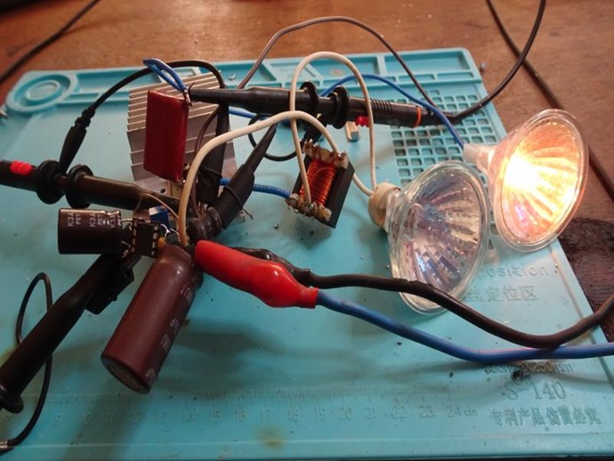
Here the images of the circuit and its tests.
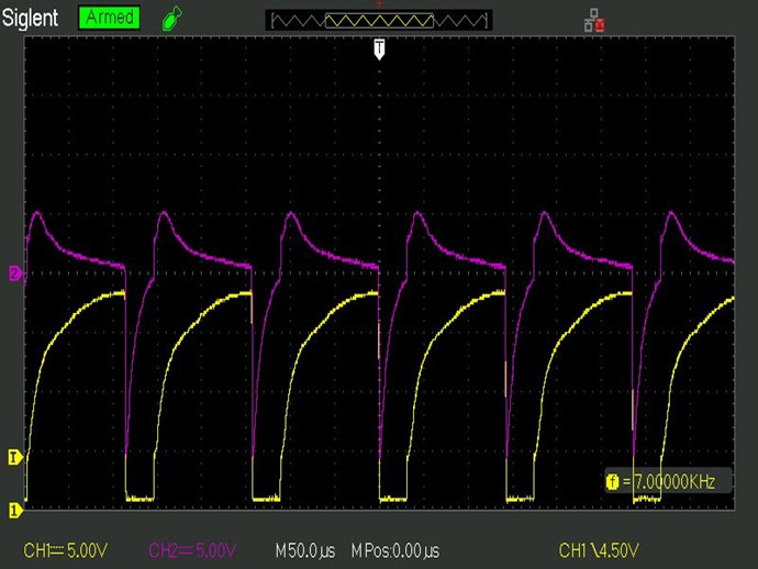
The method of adjustment is as follows.
We apply a pulse of 2uS to the mosfet, at the beginning the 500 Ohm resistor in the gate to the minimum,
with a low frequency, say 100Hz.
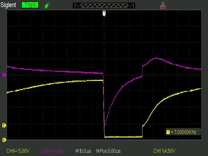
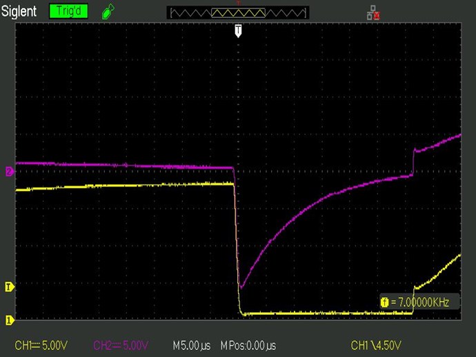
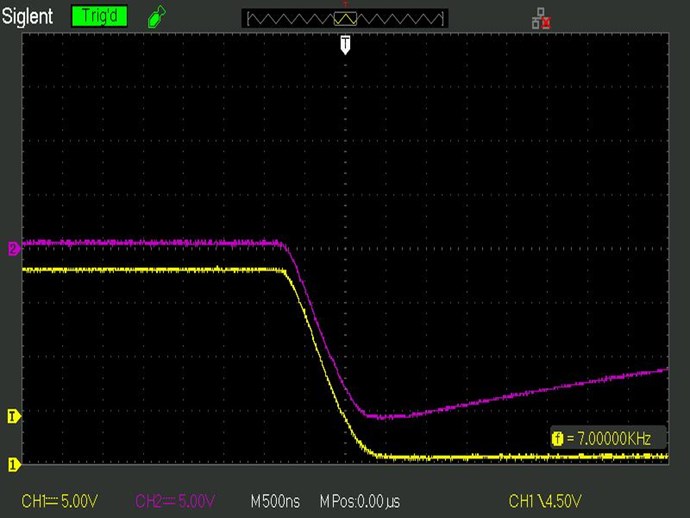
We see the response in the waveform applied to the load, we adjust Ton so that
the answer begins at its maximum negative and at the end of Ton touch 0 Vdc.
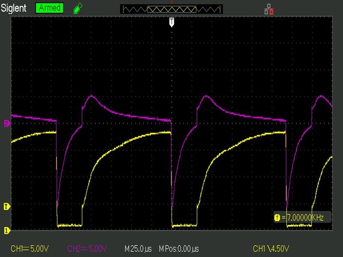
Then we verify that in drain of the mosfet during the Toff cycle the answer is
ferro-resonant, this means that the first cycle of the sine function is not symmetric.
Then we raise the frequency while keeping Ton constant.
YoElMiCrO.


