Chris
posted this
18 December 2020
- Last edited 18 December 2020
Hey Dennis,
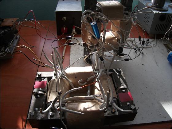
Awesome Work! This is really nice to see so many excellent experiments! Tons can be learned here!
In your image:
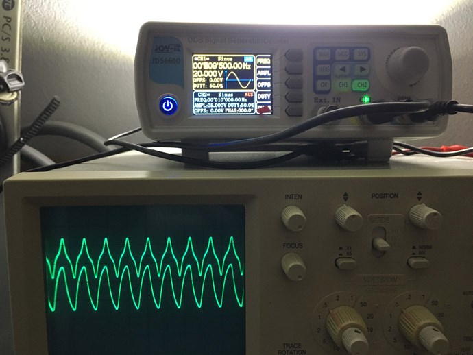
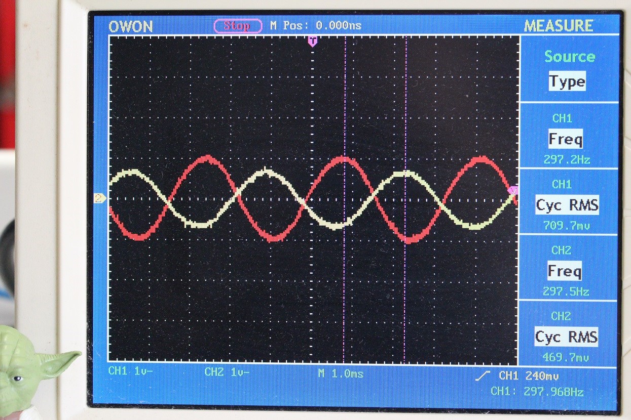
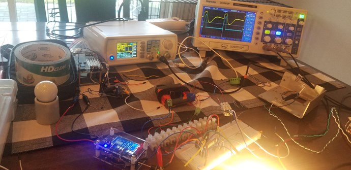
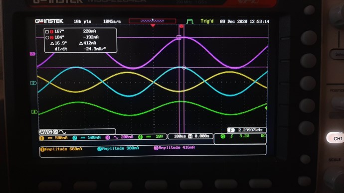
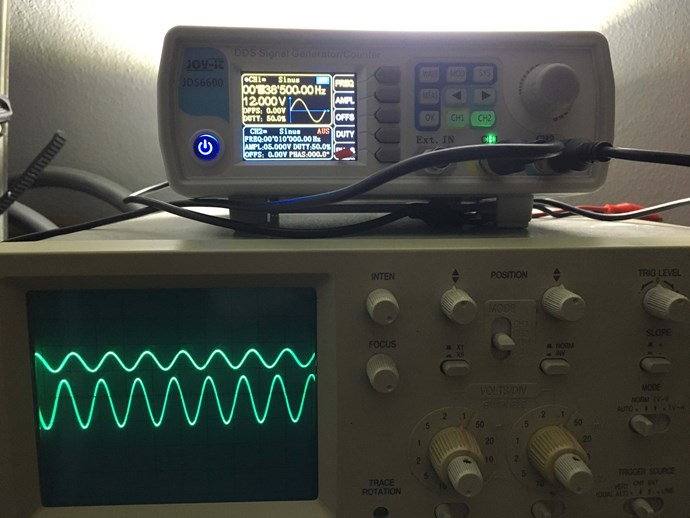
The Sharp Peaks in the top trace, in the above image, shows Core Saturation, thus the Phase Angle has been lost, Current and Voltage are in Phase. In the first Image, you show a large Phase Angle, approximately 100 Degrees.
NOTE: Research what occurs when we surpass 90 Degrees. You will not believe what you have achieved!
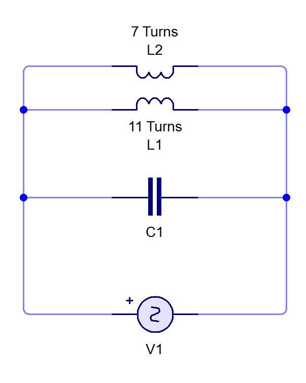
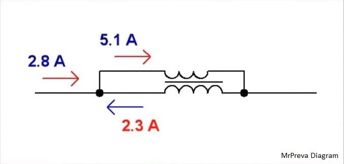
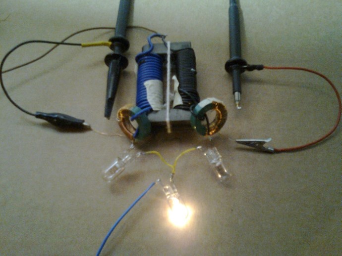
It is important to see, in this Experiment, we are Pumping Current, the Magnetic Fields, and the Opposition of Magnetic Field, in Resonance, is what pumps Current, First a Voltage is "Generated", the Voltage allows for the Flow of Current, the Current is supported by the Opposition, the Pressure, of Magnetic Fields.
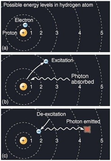
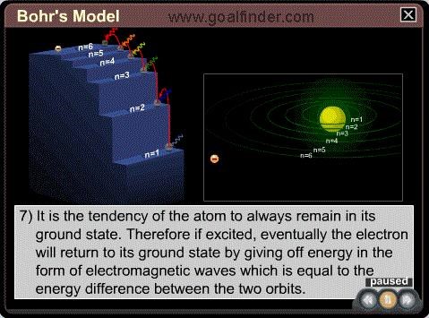
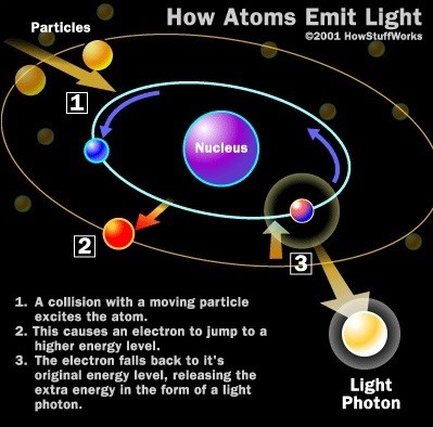
Remember Particle Physics, the Electron Orbital can be Changed by adding Energy to, or taking Energy away from, the Electron, thus changing its orbital.
Again, What Is Current? 6.24 x 10¹⁸ Electrons past Terminal T1 in one Second = One Ampere.
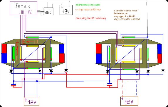
So the near Doubling of Current in this Experiment, in One Cycle, is simply the Pumping of Electrons on the Outer Orbitals. The Coils, plural, are doing Work! We have an Electromagnetic Charge Pump!
Floyd Sweet said:
The current and potential windings require relatively little power, and are applied in such a manner that rate of flow of moving charges may be accelerated beyond 1 Ampere = 6.24 x 10¹⁸ electrons/second. Thus the duty factor of the copper changes.
Losses diminish and more charges drawn from the now coherent space field flow at a faster rate as current to the load. This means as more current is required by varying loads more feedback magnetomotive forces free more electrons from binding forces complimented by potential magnetic forces of the orientated, coherent space field. Thus a conductor that formerly had temperature rise above ambient labelled as a factor of 10 would now operate at a temperature of 1.0. Thus the same gauge wire would carry 10 times more current at the same temperature.
Ref: Floyd Sparky Sweet - The Space-Flux Coupled Alternator
Learning to think like this is extremely beneficial! This is the very set of well defined constants that Power the Load! Voltage and Current. A logical sensible approach in this area is critical for all serious researchers!
Best Wishes,
Chris


.jpg?width=20&crop=0,0,20,20 "fer123")


 version1
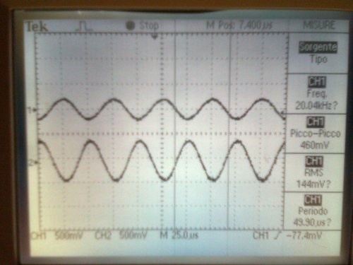 20KHz version1
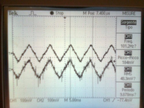 100Hz version1
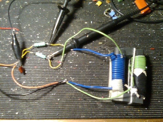 version2 sort of akula core
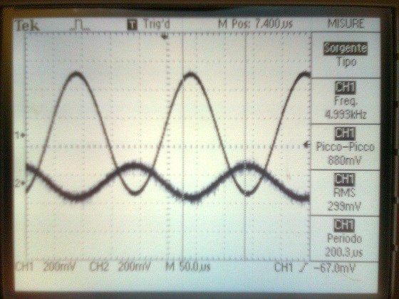 5KHz version2
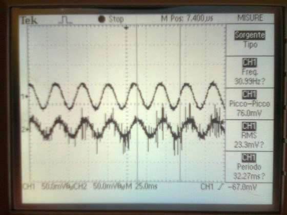 30Hz version2
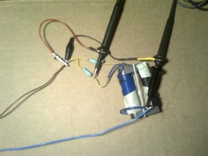 misuration 20turns coil
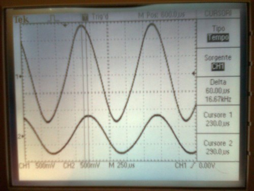
 misuration 40turns coil
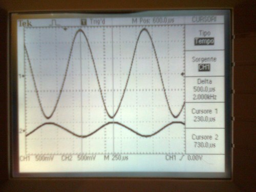
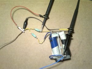
 misuration only currents shift
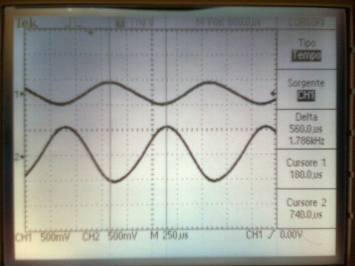
 hi!
hi!


 1
1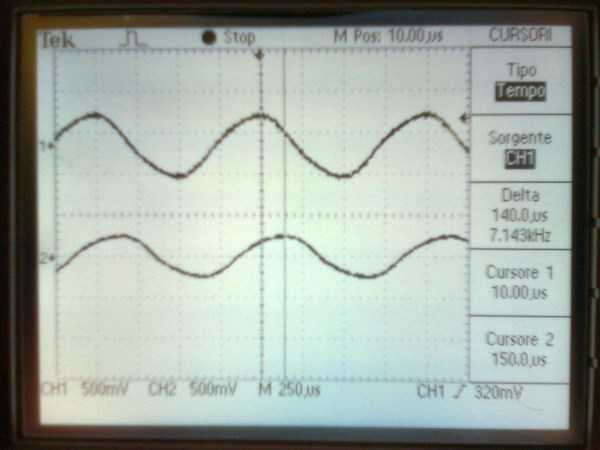 1
1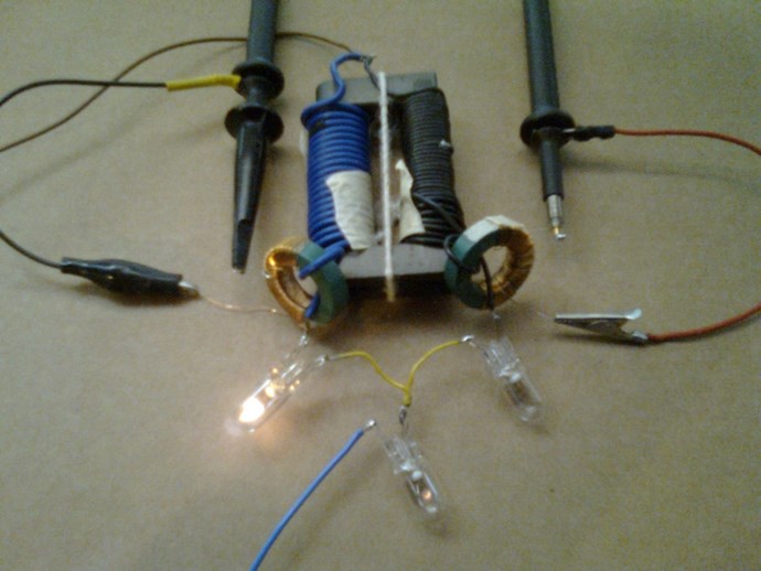 2
2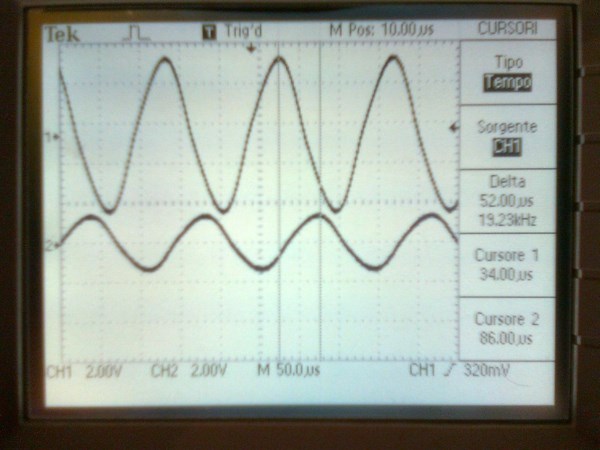 2
2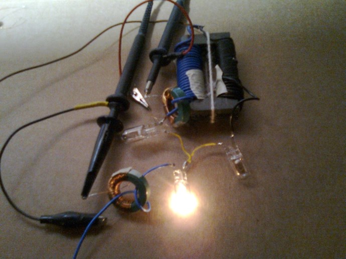 1A
1A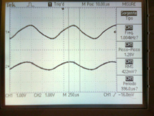 1A
1A 2A
2A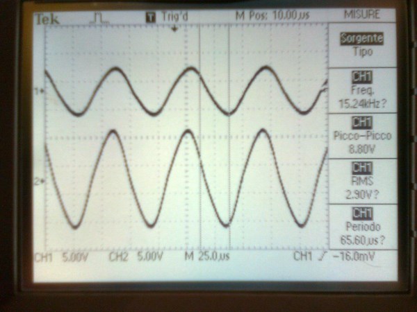 2A
2A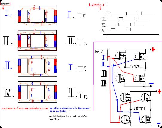


.jpg?width=690&upscale=false)
.jpg?width=690&upscale=false)
.jpg?width=690&upscale=false)
.jpg?width=690&upscale=false)

 and the good spirit of everyone here.


.jpg?width=690&upscale=false)