Melendor's bucking Coils Experiment

  • 1.2K Views
  • Last Post 07 November 2022
Melendor posted this 06 October 2022

Hello Friends.

As promised , it is my turn to post what I have learned in the last 2 years from you guys.
It is Underunity , because I have a lot more to learn , and I am seeking further advice from you.

I have here  :

3 coils in total , 1 trigger and 2 Partenered Output coils

The 2 POC 's are 50 m of magnet wire at 0.7 mm diameter

The trigger is 12 ,5 m of 0.5 insulated wire. ( 1/4 Lenght )

The core is an AMCC 200 from China.

Here they are :


Because I have learned that coil Geormetry plays a strong role in the result , I did not make the Coil Bobbin 10 cm Long , but only 4 cm.
In this situation the coils do not fit one under the other , but One near the Other.


Coil Specs are:

L1 : 12.5 m  - 1.2 Ohm - 8.5 mH   CW

L2 : 50 m     -  2.7 Ohm -  0.26 H  CW
L3 : 50 m     -  2.7 Ohm -  0.28 H  CCW


Experiment Diagram is this :


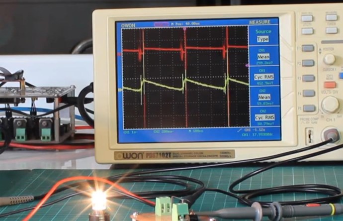
The scope Shots are this :

Yellow : L1 Gate Voltage
Purple : L1 Current
Blue    : L3 Current

Duty : 10 %

DC Bulb around 4 W.


The wire Length's are 1/4 but the turns are not 1/4

The POC have 280-300 Turns
The Trigger has 51 Turns.


The CORE Diameter Alone was small and I could build the 280 Turns , however the L1 is wound on a bigger Surface area , so I could not maintain an Equal Turn Ratio while maintaining the wire length.

I get the desired waveform , but with it or without it , the power Draw from the supply is the same.

The voltage on POC3 is not that great , so only a little bit of current flows.
I did not try to make measurements , because as Chris has said , at an early stage of the experiment , making measurements is pointless.

My experiment is similar to JOHN's his , the only diffrence is that I do not have a Gate Drive at the moment , and the L1 is not made of the same wire Gauge as the other 2 POC.

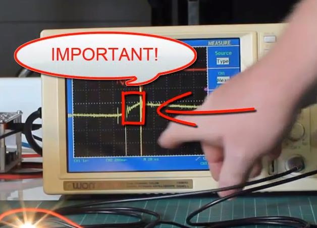
I would really love to see that "Helping" effect of the POC3 , and any advice to improve the current waveform would be Great.
I apologize if the setting is not very beautiful as yours is , but Investing in a 3D printer for the Bobbins , or an Expensive core , at this early moment of the experiment , as I have so much more to learn , was pointless from my point of view.

Thank you very much for all the hard work and your advice .

~~~ Melendor the Wizard

Order By: Standard | Newest | Votes
Jagau posted this 07 October 2022

Hi Melendor
It's very good, it's a beautiful experience that you realized.
If I read well on your function generator only 1496 hertz
for such coil with 260 and 280millihenry, I find this a bit low. Have you tried upping the frequencies?

According to your schematic, don't forget to place a 10K resistor between gate and souce, in order to avoid unexpected locking of your mosfet and unloaded the gate quickly.
Jagau

Chris posted this 07 October 2022

Hey Melendor,

Beautiful Work! Thank You for sharing!

I see you have paid special attention to get here you are today! That's nice to see, Thank You!

From what I can see, your Waveform is very close, but not yet quite right. There needs to be more Linear and have less of a exponential curve. This is, most of the time, a polarity issue between POCOne and POCTwo.

My Advice:

Start by configuring your Input Coil and POCOne into a conventional DC Transformer and take measurements with the same load.

Using conventional current and the Right Hand Grip Rule, the Current in the Input Coil, and the Current in POCOne must oppose, is Magnetic Fields Oppose.  

Now you have a Conventional DC Transformer with a efficiency of 80 to 90%.

Now add POCTwo and check the polarity until you get the Input Current Dropping under load.

Wistiti has shown this:


When you get the correct polarity, you will see the Input Current drop, and see a more linear decrease in Potential:


Increasing your Output Voltage is key to bring machines performance up, and the Partnered Output Coils Generate their own Voltage by Opposing each Other and Faradays Law becomes key to making the Machine "Generate" Voltage.

This "Generation" phase occurs in the Important part:


Your Input Coil controls the Δt in the Rise Time here, where your POC "Generate" their own Voltage and therefore Pump Current as a result. Thus the Input Coil may need to be changed, played with, tuned, to make your Partnered Output Coils "Generate" sufficient Voltage.

Remember, when tuned, when you reach the Harmony of Magnetic Resonance, your Input will be very small to nothing!

Best Wishes,

   Chris


P.S: Let your POC do all the work, bring your Magnetic Fields Up, this means Currents need to be sufficient in your POC, which in turn means you need to "Generate" sufficient Voltage in your POC. POCOne "Generates" POCTwo's Voltage, and POCTwo "Generates" POCOne's Voltage, so there is a Harmony of Magnetic Force, H and Density B, a Magnetic Charge Pump. 


baerndorfer posted this 07 October 2022

hi melendor,

you have a working circuit there - congrats! 😎

as far as i can see the output coil is doing it's job. when the input current from L1 is not present, you still have a current on the output side.

at this stage i would....

1) improve the coil itself (more precise windings)

2) test different POC connection methods (described in chris building thread)

3) try to reach higher frequencies (it is easyer to get good results in the higher regions)

have a nice day!

scalarpotential posted this 07 October 2022

Hi Melendor,
Neat work. Some thoughts:
I'd measure the following just to get a better picture of what is happening and to see if the measurements can be predicted by what you use:
Voltage on L1, L2, L3, all connected.
Voltage on L2 and L3, both not connected, then one of either connected.
If you want L3 to assist L1, the voltage must net to a positive voltage in the direction of the diode and must be higher than 0.7V, V3 is the sum of voltage induced by i1 and i2, but the polarities are opposite.

Chris posted this 07 October 2022

Hey Guys,

Baerndorfer and Scalarpotential are spot on!

Baerndorfer is very advanced in this Field, so his words are always Wise Words. 😉

The Magnetomotive Force, M.M.F, is Current I through Turns N, NI, which is also Ampere Turns AT = NI, is the Force of the Magnetic Field , or Magnetic Field Strength, H if one accounts for the Magnetic Path Length l.

Each Field must be sufficient to do Work on the Other Coils.

Applying Ohms Law, Voltage V / Resistance R = Current I,  therefore, we must have Sufficient Voltage V for Current I to flow, and achieve this task.

Getting your Fields Up will help your Machine come to Life!

The Peak Voltage Amplitude:


can be achieved with very little Input Current, as each Partnered Output Coil acts as a "Generator", one as Stator Coil and one as the Rotor Coil:


Here we have two Stator Coils, so imagine them as one POC, and the Rotor Coil as the Other POC. 

Partnered Output Coils have the same Symmetry as a Conventional "Generator" or Transformer, however, we have Asymmetry, because our Input Coil sees very little to none of the Negative Torque a "Generator", or Negative M.M.F a Conventional Transformer has, thus reducing the Input Coil Impedance and pushing up the Input Current as the Output is loaded more and more.

Focusing on Magnetic Force, and negating it, is the key to getting Above the Unity Boundary!

As L3 is turned On and Off, you should see a difference in Magnetic Force, as Member Wistiti has shown. This is the start, as I said, Increasing the Voltage on your Coils is key to gaining greater Magnetic Field, and as the Magnetic Field Increases, the Output Increases, as Faradays' Law tells us.

My Friend, you're doing a great job! Well Done! I hope we are not bombarding you with too much info at once?

Best Wishes,

    Chris

Melendor posted this 14 October 2022

Hello @Chris and  Team !
Thank you very much everybody. Wise advice I received from all of you.
I am humbled and very Grateful !
I have been working in the last week to improve my Device as you all suggested.
All the advice was important , and I went directly into it.
This is only a small Update , and I hope that in 2-3 days I will post pictures and scope shots.

Improvements : The 5 Ohm Rds ON , mosfet was replaced with a 0.15 Ohm Rds ON one.
                          The 12.5 m - 0.4 mm L1  was replaced with 8 m - 2 mm Trigger Coil.
                          Added 10 Ohm Resistor between SG and Gate  and a 10K Gate to ground.

                          Added the 4th Oscilloscope Probe , to get 4 traces of the circuit.

                         Added a 0.05 Non Inductive Resistor Mosfet to Ground to see how the Input current looks like.

Thank you very much for all the great advice and patience !
I will show the results in a few days !
Stay Safe
~~~ Melendor the Wizard !


Chris posted this 14 October 2022

Hey Melendor

All very good improvements! Thanks for the update!

It is worth keeping in mind:

POCOne "Generates" POCTwo's Voltage and POCTwo "Generates" POCOne's Voltage. There is a Harmony of "Generation" occurring here!

It takes some time to get this right, some experimentation is required.

It is wrong to assume the Input Coil requires a lot of Peak Power! Some power is required yes! But this Input Power comes down as one gets the machine running properly! Almost no Input Power is required when one has the machine running correctly! 

We will help you reach your goal and beyond!

Best Wishes,

    Chris

Melendor posted this 04 November 2022

Hello Team !

As promised, I am back , with some improvements to the device.
I tried to make L3 to help a little bit the  Input coil L1  but I did not have any success.
With diode Forward , reverse and without any Diode , the L3 does not want to work with me.

In this situation,I took the L3 out , and focused on L1 and L2 , to get the correct polarity.

The circuit diagram with the correct polarity is this :


The Bobbin looks like this with the improves 1.5 mm wire.


Scope shots for the Schematic above:


Circuit 1 : ( Diode in the Correct direction)


Circuit 2 : ( Diode in the wrong direction)


Circuit 3 : ( No diode in the circuit )


Conclusion from all 3 circuits :

LENZ Law applies automatically and the current flows in L2 , so that it creates a magnetic field to Oppose the L1.
It does not care if we have a diode or not. It is flowing his way.
Because of this we get X waveform and Y current draw.

Now, if we place a diode into the circuit , and we respect LENZ law , there should not be a significant difference between with DIODE or Without.
However , if we place the diode that the magnetic fields ADD , of we try to avoid Magnetic field Opposition in the Transformer , that X and Y will be totally other fish food. ( in the bad way )

In this situation , it is my opinion that circuit 1 is the correct one.
(Please correct me if I am wrong )
.
!!!
With the Flyback Diode to the mosfet  , I get a 30% improvement in light with 0 extra input.
I blew 5 mosfets , before i noticed that I need a diode to redirect the inductive spike.
Thanks to @Jagau in Melnichenko Effect and his explantion there , I also tried to Recover the energy that I used to Magnetize L1.
The inductive Spike goes back to energize a little bit L1.

As improvements from the last circuit I have:
- 10Ohm  and 10k Ohm resistos to Mosfet , 1.5 Speaker wire as Trigger 1/4 Lenght of the L2/L3 ,Flyback Diode.

If I did something wrong , Advice would be gladly taken.
Also , any suggestions how to  make L3 talk to L1 , would be great.

Thank you very much Team !
Stay Safe !
~~~ Melendor the Wizard !


Chris posted this 04 November 2022

Hey Melendor,

A good effort there! Excellent work there mate!

Yes, you're right: L1 opposes L2, L2 opposes L3 and L3 assists L1, there is the Law of Asymmetrical Electromagnetic Induction.

Very simple, if L2 and L3 Oppose each other, one must always Assist L1, right? It cant be any other way!

The Curves, seen here:


Are not what you want!

You're pretty close here:


Nice straight lines, but not much of the Straight Lines! Marked in Red!


Maybe a review of my video:


So, in: "Circuit 2 : ( Diode in the wrong direction)", you have a pretty close match, but there is a few problems here:

  1. Not enough turns.
  2. Coils Geometry can be maximised.
  3. Tuning can be improved.


See Coil Geometry for more information and also see threads on Antenna Theory for tuning.

The Voltage Generated in each POC is a function of Delta t of the Magnetic Field, Delta B, that each Coil sees, so you will have to focus on the Partnered Output Coils as they Slap Together, this is where the Coils "Generate" Voltage, and then Pump Current.

Imagine each Partnered Output Coil as this young guy, but in Duality, the Ocean Wave, is the Magnetic Field, from the opposite Partnered Output Coil, Two different Ocean Waves, two different guys:


This poor bloke is going to be in real trouble isn't he! He is going to be swept off his feet for sure!


This is an entirely natural occurrence, the Standing Wave:


Let your Coils do all the work, that's what the goal is, your Input is only to control this action, like a small tickle under the chin!


This is the condition you are invoking between your Partnered Output Coils, but only when enough Current can flow, to make this work, not forgetting, Current is entirely dependant on Voltage and Resistance. Ohms Law: I = V / R

So you're close, don't give up, focus on Exactly What is occurring here, this is important to understand! Its all in focusing on the Effects! These Effects!

Experiment is the only real path forward, making sure you understand exactly the processes occurring!

Again: Please don't give up, you're there, you only need to focus on the actual Effects seen!

Best Wishes,

   Chris

P.S: Re Tuning; On your Input, you have a very long flat top, this means you can reduce your Duty Cycle greatly, also your Frequency can go up a lot, until the flat top, and dead, off time, is gone and all you see is the Ramp Up and a Ramp Down! I would consider this a successful replication of the effects, it only needs work to improve the Effects seen!

Chris posted this 05 November 2022

Hey Melendor,

I also meant to say: You have to spend a little bit on the Input.

Of course the goal is, to spend a little bit on the Input but get a lot on the Output!

I would suggest, for the moment, do not worry about the Input yet, maximize the effects shown and then start looking at the data.

Also, the Ocean Wave, knocking the young guy off his feet:

Imagine each Partnered Output Coil as this young guy, but in Duality, the Ocean Wave, is the Magnetic Field, from the opposite Partnered Output Coil, Two different Ocean Waves, two different guys:


This poor bloke is going to be in real trouble isn't he! He is going to be swept off his feet for sure!


This is the Ramp Up Portion of the Phase:


Best Wishes,

   Chris

Melendor posted this 06 November 2022

Hello Chris and Team.


Thank you for the Advice and for your time !
It is all much appreciated !

From the experiment above,I made the following modifications :
- I gave up to the 1/4 ratio  12.5 m Primary , 50 m POC 2 and 50 m POC 3

Now I have :

L1 : 3.5 m  15 Turns 0.3 Ohm  0.85 mH

The waveform is this:

L1  Current  -  YELLOW
L2  Current   - BLUE ( with 5 W Load ON  it)
L3 Current  -   VIOLET  ( Diode + resistor )

2 KHz at 6% Duty Cycle with 15.4 V , 0.31 A  in a 5W lamp


Any suggestion or critic , will be taken in the most constructive way.
I appreciate your time and help.
Thank you very much.

~~~ Melendor the Wizard

Melendor posted this 06 November 2022

I apologize for the double post, but I forgot to post the schematic above,and I can not edit the post.
Here is the schematic:


Thank you.
Stay Safe.
~~~ Melendor the Wizard

Chris posted this 06 November 2022

Hey Melendor,

This is excellent work! Very nice to see!

In this image:


I believe you have exactly the correct waveforms!

I see a small curve, but think its just the Core, so nothing to worry about!

If you put a Switch on L3, and turn L3 on and then off, do you get an Input Power Drop when your L3 Coil is On, when the Switch is in the On State? Of course, the more Current Assisting L1, from L3, the less Input you spend, and the more Output you get!

This is excellent work! Well done! Time for you to go on the Successful replications list I believe!

All you need to do now, is keep working on improving this effect, the higher the Amplitude on the Coils, the more output you get!

Your input Coil can also span both coils if you wish, making sure one Partnered Output Coil is CW and one is CCW, then the total mutual coupling between POC and Input is Zero!

Also, use the Diodes as Polarity, and Parallel the Partnered Output Coils, with the right Polarity, to double your Output Power! As you have Current and Voltage on the Shorted Coil, that is entirely Ignored currently! Power that is not currently Counted in your Output

Best Wishes,

   Chris


Chris posted this 07 November 2022

Hey Melendor,

My Friend, a Question for you:

In any way, did you find this set of experiments Hard? Or expensive?


Best Wishes,

   Chris

Melendor posted this 07 November 2022

Hello Chris and Team.

First,I want to answer the questions.

In my experiment , the Core AMCC 200 , is not the best one , and I accept that.( is not Hitachi metals)
It operates best at frequencies between 100 Hz and 10 Khz.
To get Power Transfer / Generation at 600 KHZ as member Fighter and Captain Loz did , that is Impossible for me at this stage.

Also , the lenght of the core is 8 cm.
I did not build a Bobbin of 8 cm long , because I had information about coil geometry , so I build the bobbins at around 3 cm each , and placed them one near the other on one side of the AMCC core.

This is not enough , and I will rebuild my bobbins , to 1.5 Cm in lenght.
This should take my experiment to the next stage , because now I am UNDER-unity.


What does this mean, is that the Bobbins will look like in  Tinmann's Magnetic diode video.
If you guys do not know about his experiment , you can watch it here:
https://www.youtube.com/results?search_query=magnetic+diode


In any way, did you find this set of experiments Hard? Or expensive?


No Chris.


These are the Basics that everybody should know.
To power a house, you will need Power in the KW  Range.
If one can not power a 5 w Lamp  , than 5 KW / h means Death.

I have seen "fights" against you Chris where people are saying that you need a signal Generator , Osciloscope , Multimeter , coils etc etc and that it does not cost 20 Euro like you said.

In this situation people must understand that , their point of view is wrong.
It is common sense that to drive a car..you need TIRES.
You must not complain that the tires cost money.

Every person that want to do experiments, must have some basic equipment to do experiments with.
You are in the business of Aboveunity or in the business of Working the land planting potatoes?

1 DM ( Digital Multimeter) , costs as much as 1 pack of Cigarettes.
1 Coil costs the same.

So,if you want it , you can do it !!!!

Also , it is very important to have patience and trust the process !
If you play , a little here, a little on the other forum...etc....you will not get far.

Bad times will come,so I urge everybody to stop complaining and start doing the work.

Me , I will improve my device , and I will post again in 1 week , with the improved version of it.
Thank you Chris and TEAM !

~~~ Melendor the wizard.

Chris posted this 07 November 2022

Hi Melendor,

It is a very easy misconception to assume Below Unity Status, when a closer look will reveal an Above Unity State.

We saw this with Captainloz, and a few others, in looking closer, we saw that the previous assumption was wrong, so don't be surprised if you're actually sitting in a better position than you may currently believe.

1.5 Cm in lenght


Reducing Coil Length increases the Magnetic Field Density, B, for the same Current, but the Current also depends on Voltage, don't forget the relationships here.

You're making excellent progress, so don't give up! This is the start of a whole new Tomorrow!

I am very proud of this excellent Progress you and so many others are making. Congrads!

Best Wishes,

   Chris

P.S: There are a lot of Twits out there that do nothing but complain, I am not interested in them, I only aim to expose their total uselessness of Existence! I prefer to focus on people like you, that is not scared of a little hard work, all in the name of Progress!

We're Light Years Ahead!
Members Online:
What is a Scalar:

In physics, scalars are physical quantities that are unaffected by changes to a vector space basis. Scalars are often accompanied by units of measurement, as in "10 cm". Examples of scalar quantities are mass, distance, charge, volume, time, speed, and the magnitude of physical vectors in general.

You need to forget the Non-Sense that some spout with out knowing the actual Definition of the word Scalar! Some people talk absolute Bull Sh*t!

The pressure P in the formula P = pgh, pgh is a scalar that tells you the amount of this squashing force per unit area in a fluid.

A Scalar, having both direction and magnitude, can be anything! The Magnetic Field, a Charge moving, yet some Numb Nuts think it means Magic Science!

Message from God:

Hello my children. This is Yahweh, the one true Lord. You have found creation's secret. Now share it peacefully with the world.

Ref: Message from God written inside the Human Genome

God be in my head, and in my thinking.

God be in my eyes, and in my looking.

God be in my mouth, and in my speaking.

Oh, God be in my heart, and in my understanding.

Your Support:

More than anything else, your contributions to this forum are most important! We are trying to actively get all visitors involved, but we do only have a few main contributors, which are very much appreciated! If you would like to see more pages with more detailed experiments and answers, perhaps a contribution of another type maybe possible:

PayPal De-Platformed me!

They REFUSE to tell me why!

We now use Wise!

Donate
Use E-Mail: Chris at aboveunity.com

The content I am sharing is not only unique, but is changing the world as we know it! Please Support Us!

Thank You So Much!

Weeks High Earners:
The great Nikola Tesla:

Ere many generations pass, our machinery will be driven by a power obtainable at any point of the universe. This idea is not novel. Men have been led to it long ago by instinct or reason. It has been expressed in many ways, and in many places, in the history of old and new. We find it in the delightful myth of Antheus, who drives power from the earth; we find it among the subtle speculations of one of your splendid mathematicians, and in many hints and statements of thinkers of the present time. Throughout space there is energy. Is this energy static or kinetic? If static, our hopes are in vain; if kinetic - and this we know it is for certain - then it is a mere question of time when men will succeed in attaching their machinery to the very wheelwork of nature.

Experiments With Alternate Currents Of High Potential And High Frequency (February 1892).

Close