John's Non-Inductive Coil Experiment

  • 1.3K Views
  • Last Post 28 December 2020
John posted this 22 December 2020

Hello everybody,


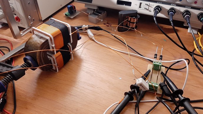
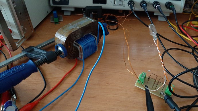
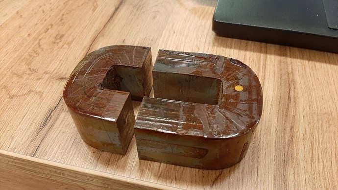
I started my own replication of Non-Inductive experiment. Now it is just few things which I have done. At first, in my replication I have used laminated iron C-shaped core. I am not sure, that it is good choice, but many of you can tell me that. Maybe it will be better to use ferrite or nanocrystaline core.

From first measurement I do not have good results. But I hope that I will progress soon. I tried standard rectifier diodes as well as ultrafast.

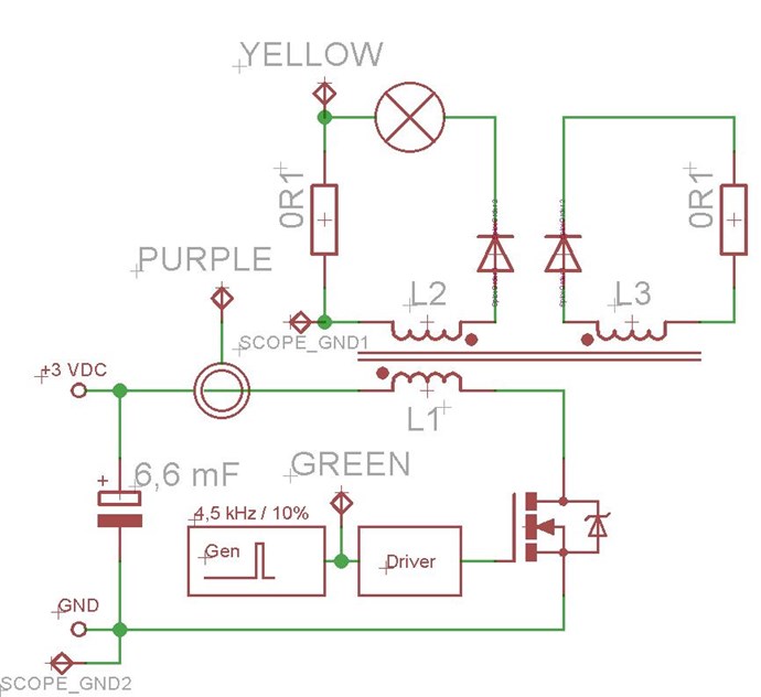
My schematic looks like this:


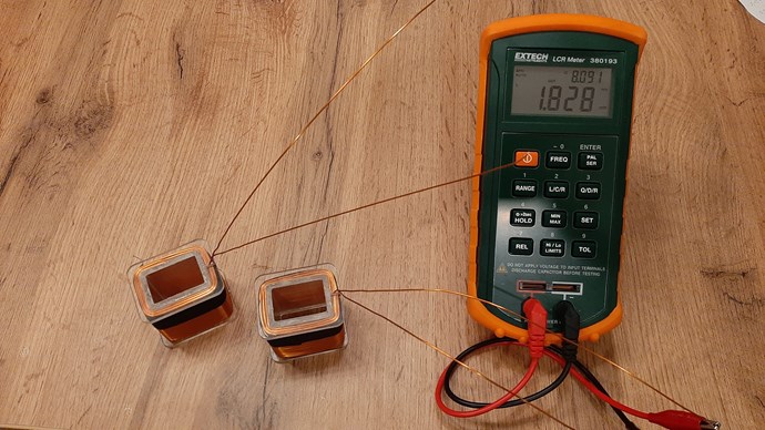
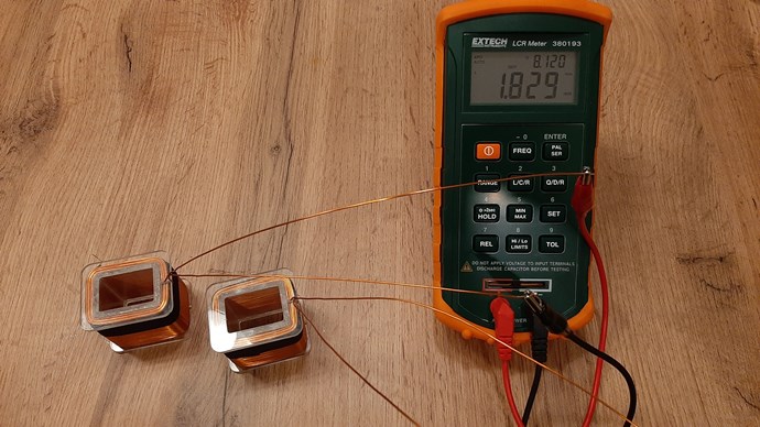
Some numbers of my system: (I tried to wind the coils quite precisely)

Coil L1 (primary): 26 turns of 0.8 mm (maybe it would be better more thicker)

Coil L2 (secondary under primary): 260 turns of 0.8 mm

Coil L3 (separately secondary on the other side of the core): 260 turns of 0.8 mm

Core: laminated iron core from old transformer - 30 x 21 mm (630 mm 2) cross section.


Inductances (on core):

L1: 1,73 mH, 0,16 Ω

L2: 190 mH, 1,43 Ω

L3: 190 mH, 1,42 Ω


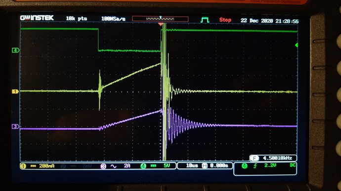
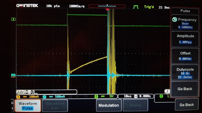
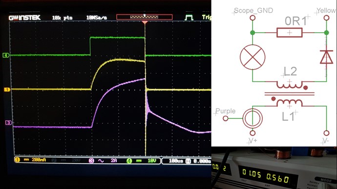
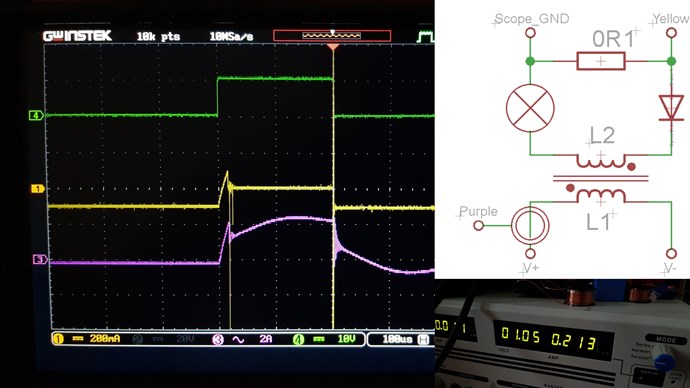
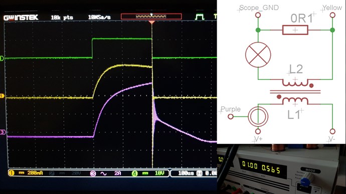
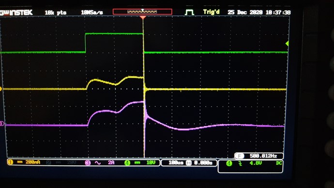
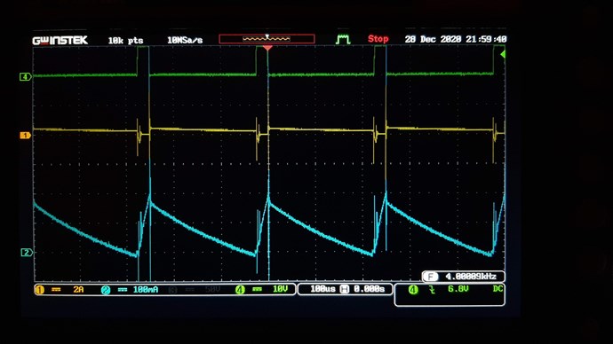
Green - signal from generator (negated because of driver)

Purple - input current waveform

Yellow - L2 circuit waveform


Now I dont know if it is caused by the core material or the coils. I measured signal on L3 circuit, but it was very weak. Only pulses on edges of trigger pulse.


I hope that soon it will be looks better.

Have a nice day.

John.

Order By: Standard | Newest | Votes
Chris posted this 22 December 2020

Hi John, 

Excellent to see! You will notice I have moved your post out to its own thread, this will help you and everyone else help, and keep progress.

First up: Thank You for Sharing!

Don't change anything except for the Concrete Resistor, that needs to be replaced, and that's all.

Scope Shots, are showing a few things. We don't see the Asymmetrical Sawtooth Waveform, but we will get you there.

Start by following the following procedure:

  • Keep the Input Coil Polarity as it is.
  • Disconnect entirely, L3.
  • Get L1 and L2 in Transformer Mode, use the Right Hand Grip Rule to make sure the Polarity is right, remember Opposing.
  • Once you have this done, then Connect L3, this has 2 Polarities, one will work and you will get the Asymmetrical Sawtooth Waveform, and one you wont. Find the one that does give you the Asymmetrical Sawtooth Waveform.
  • Then, tune Input and Input Coil to match optimum Output Result.


The Asymmetrical Sawtooth Waveform on the Output:
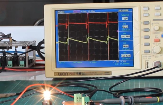
 

The Lengths of the Coils play a role here. The Run Frequency should be a Fundamental Resonant Frequency, or a Harmonic of the Fundamental. At Harmonics, one will need the Input Voltage to go up by the same factor. We try to aim for 1/4, or Quarter Wave length of the Partnered Output Coil and the Primary, so this would mean, if a single Partnered Output Coil is 100 meters, the Input Coil would need to be 25 meters.

Resonance does not need to be 100's of KHz!

I often have my machines running down around 3 to 5 Khz, sometimes less. So don't let "Conventional Wisdom" lead you astray!

The Effects you observe are where the Path Forward lays! So let your instinct and intuition lead you, not your "knowledge"! Knowledge is a dangerous thing, especially when one can not distinguish between observation showing incompleteness and inaccuracy's, in that Knowledge! I have seen this many times from so called experts in the field! They get angry when they can not explain very simple things they have not ever observed before! So beware of those people!

Your Input Coil needs to be completely off after the Initial Pulse, see here:
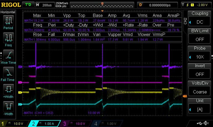
 

The Power, seen here, Changes! After Switch Off, we see: 1 x -1 = -1, see the Argand Diagram for more information.

A much greater number can be sent back to your Power Supply, once you have the correct operation, here is an example:


Input Power Drops 68% Under Load!

Lastly, don't give up! You have a World Leading Team of Experts here! Something you will not get anywhere else! We will help! So be patient and force your mind to think Simple! Don't over Complicate this! 

Thank You for Sharing!

Best Wishes,

   Chris
John posted this 23 December 2020

Hi Chris,


At first, thank you for create that thread. I considered it, but in the end I put it where you saw it.

Causes which you described I tried before I wrote first post. I changed polatities of the coils, changed polarity of the diode in L2 circuit, changed resistor load to bulb and everything around it. There are only few thing which may be wrong.

Here is some photos with description.

Reversed polarity of L2 (secondary)

Same polarity L1 and L2, reversed diode in L2 circuit

Tried to change duty cycle to first break-down signal of L2 but nothing to change

Bulb load instead of power resistor.


I also tried change frequencies and duty cycles, but no dramatic changes occurs.

But I'm not giving up, it's just the beginning !


Have a nice day.

John

Chris posted this 23 December 2020

Hi John, 

I find it easy to think:

Action, Reaction and Counter-Reaction


Keep at it, don't give up! Its easier than you think, its just a case of getting ones mind in the right Mindset! Thank You for Sharing!

Best Wishes,

   Chris
  • Liked by
  • Jagau
  • cd_sharp
Vidura posted this 23 December 2020

Hey John, Good to see joining more members on this. It's very interesting to see a silicon steel core based experience. As many of the machines of last century used this material, and also tinman's RT, it should perform well. I can see that in your scope shots the signal is inverted in some, in others not(not relevant, but can be confusing). Maybe you should try to get a faster rise time, less turns and a thicker wire on L1, you could use 1.5 or2.5sq.mm pvc coated wire. Pay attention to the ramp up of the current, you should see a steep rise on the first part, see cd Sharp's latest videos. Also it is advisable to monitor currents in L2 L3 both. Wishing you success, Vidura

Vidura posted this 24 December 2020

Hey John, I was reviewing your experiment again, if I may ask a few questions: In your current traces there is a break after 20us or so. Do you use a driver with current limiting circuit? If so, you might need to adjust the CS resistor, or disable this feature. For this kind of core it might be required tu have more current, and longer Ton pulses, the frequency also might be well below 1khz for silicon steel. Regarding the currens in L2, L3, it is important to have a significant amount. You might also need to change the load (lower resistance?). If still no current in L3, check the diode and CS resistor, if not damaged. I hope this helps some. Vidura.

John posted this 25 December 2020

Hello Vidura,


I checked the diodes and CS resistors and everything is good, but it can be possible that my input capacitor bank was disconnected as you can see on one of the measurements.

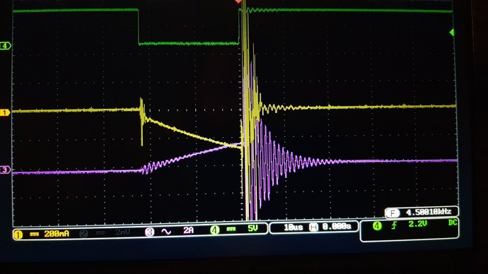
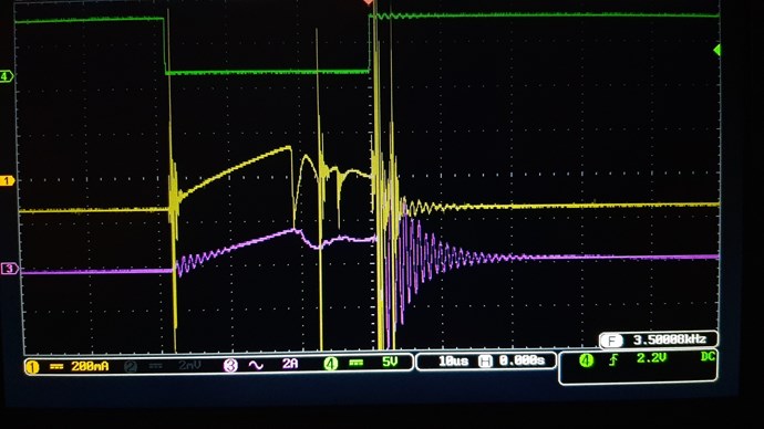
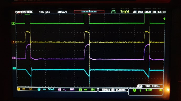
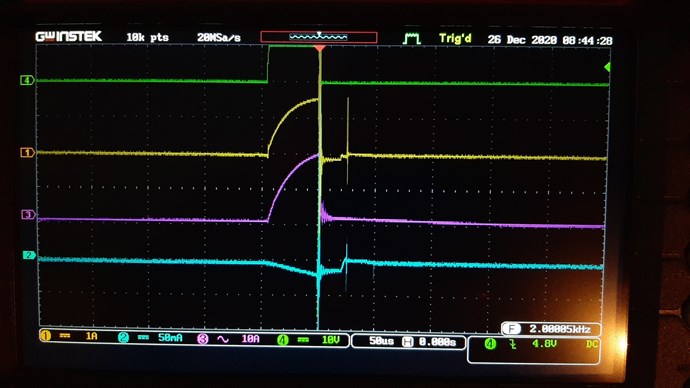
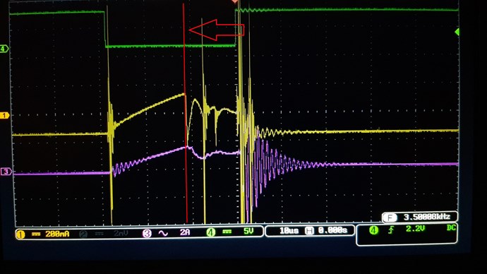
I made some simple measurements (maybe usefull for someone else). My measurements was only with two coils (transformer mode) as Chris recomended. Diode in L2 circuit is ultra fast type UF5408. In scope shots are only three signals. Green - mosfet gate signal, yellow - current of L2 circuit (on 0R1 CS resistor), purple - L1 input current measured through Hall sensor.

As primary coil L1 I used 14 turns of 1,5mm2 wire with PVC isolation, secondary L2 has 260 turns of 0.8 mm.


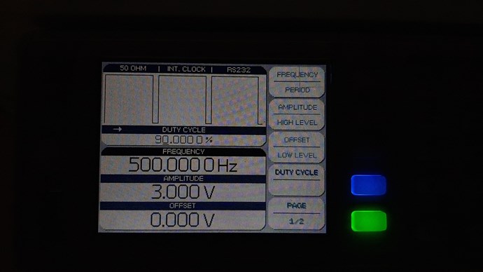
Frequency 500Hz with 10% duty cycle (inverted because of the mosfet driver which is used).


And one measurement without capacitor bank and without diode in L2 circuit

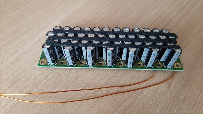
And capacitor bank 44x 150uF / 63V


Measurements will be continue.

Have a nice day.

John

Chris posted this 25 December 2020

Hi John,

I would suggest, making any "Measurements" will be of little, to no use. I don't recommend making any "Measurements" until one has a machine they understand, and have the right waveforms seen and understood.

We all know, a conventional Transformer is around 85% efficient, and if you have achieved this "Transforming" effect, then this is all you will get! From Primary to secondary, in a closed core transformer, this should be the expected figure.

Add L3, get this right, get the polarity right and then focus, concentrate on the Sawtooth waveform and achieving that goal and then maximising on this, Energy must be "Generated" in Excess of the Input, so a means of Generation is required, this is the Sawtooth waveform.

There arrears to be something wrong with your capacitor bank, for these experiments, I would avoid using it!

Best Wishes,

   Chris
 

John posted this 26 December 2020

Hi Chris,


I appreciate all your words and recommendations, but I just wanted to test the behavior of the core with another primary coil (increase in power-on current). I know that we are looking for sawtooth waveform.

I have a very weak signal on the L3 circuit, so I was confused if I did something wrong on the L1 / L2 side because there the currents are much larger (see the channels gain).

Now I have made L1 from 1,5 mm2 - 14 turns (recommendation from Vidura), both secondary coils are from 0.8mm and 260 turns. (I wrote it before)

I tested it with 500Hz / 10% and 2kHz / 10% and I see that the core responds better at lower frequencies, which is to be expected, as it is a core for classical transformers.

Green - mosfet gate, Yellow - L2 current, Purple - L1 current, Blue - L3 current

Light bulb as load in L2 circuit

500Hz

2 kHz


Have a nice day.

John


Vidura posted this 26 December 2020

Hey John, Hopefully I did not confusing you. The best for the instance would be to follow Chris' advice to build a good conventional transformer as a first step, considering the ratio of primary-secondary, to adjust output voltage and current convenient for the Load. I saw that there is not much space for a primary winding with PVC insulated wire, with such a few turns the ratio might be to large. For your 260t sec. I would guess 60-70 turns could be appropriate. For space constraints you might have to return to magnetic wire. Play a bit with this, try different loads, single output coil, until finding the best performance. Then proceed connecting L3 and diodes, to achieve the sawtooth wave. Vidura

John posted this 28 December 2020

Hello everybody,


I tested my laminated iron core with different setup of primary coil. Slightly increased primary turns from first setup. Secondary coil tested with different loads and here is the result.

L1: 52 turns, 0.8mm, 9m

L2 and L3: 260 turns, 0.8mm, 36m

scope traces: green - mosfet gate signal, yellow - L2 current with bulb load, blue - L3 current

Frequency 4kHz / 10% duty cycle

Have a nice day.

John

Chris posted this 28 December 2020

Hi John,

Thank You for Sharing! You have achieved the Goal! Congratulations! You have everything right!

I recommend to Document everything, images, video and text!

At this stage, its important to remember that we are at the start! Like any technology, improvement comes with Iteration and Understanding and Experiment, I always go back to Floyd Sweet, early machine, Tom Bearden reported 6 watts and Floyd Sweets last machine was 5KWatts.

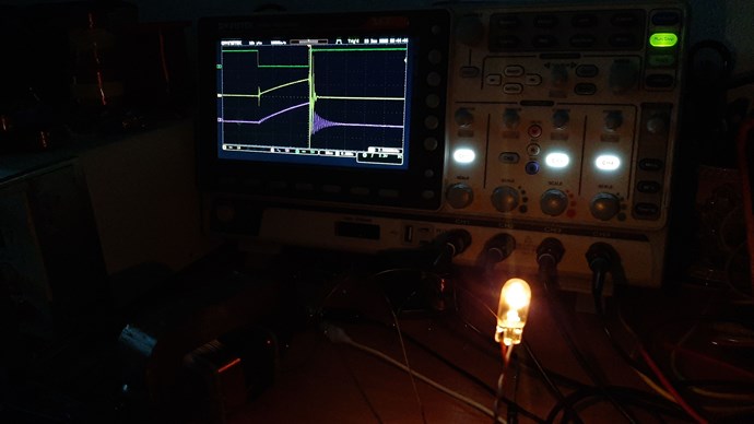
This image says it all:


Well Done, Congratulations! I will add your name to the list! I see you have a very good understanding of Asymmetrical Magnetic Fields and Asymmetry of the Machine!

Best Wishes,

   Chris
P.S: Make sure your Input Coil is sending Power back to your Input, so Used power is much less than the apparent power.

John posted this 28 December 2020

Chris, 

thank you for lot of the materials that are here to study and for your advice !


Vidura,

also thank you for your advice !

Chris posted this 28 December 2020

Hi John,

There is a massive amount of information to learn here! Massive Improvements can be made from where we are right now. This is just the start. Study your machine as much as you can. 

You will see the connection to The Mr Preva Experiment now you have gotten this far!

Paul Raymond Jensen said:

This resulted in a current gain in the secondary, relative to the primary. Lenz's law was bypassed, and free-energy resulted. An alternate explanation for the current gain in the UDT is to consider each secondary winding as acting as the primary winding for the other secondary winding when an output current is drawn because the two secondary windings generate geometrically opposing fields.


You have Three Sources of Energy, only one you had to put in! Where does this Extra Energy enter the System?

Thank You for coming, Being Part Of Something Better! Only together, can we change the world!

Best Wishes,

   Chris

We're Light Years Ahead!
Members Online:

No one online at the moment


What is a Scalar:

In physics, scalars are physical quantities that are unaffected by changes to a vector space basis. Scalars are often accompanied by units of measurement, as in "10 cm". Examples of scalar quantities are mass, distance, charge, volume, time, speed, and the magnitude of physical vectors in general.

You need to forget the Non-Sense that some spout with out knowing the actual Definition of the word Scalar! Some people talk absolute Bull Sh*t!

The pressure P in the formula P = pgh, pgh is a scalar that tells you the amount of this squashing force per unit area in a fluid.

A Scalar, having both direction and magnitude, can be anything! The Magnetic Field, a Charge moving, yet some Numb Nuts think it means Magic Science!

Message from God:

Hello my children. This is Yahweh, the one true Lord. You have found creation's secret. Now share it peacefully with the world.

Ref: Message from God written inside the Human Genome

God be in my head, and in my thinking.

God be in my eyes, and in my looking.

God be in my mouth, and in my speaking.

Oh, God be in my heart, and in my understanding.

Your Support:

More than anything else, your contributions to this forum are most important! We are trying to actively get all visitors involved, but we do only have a few main contributors, which are very much appreciated! If you would like to see more pages with more detailed experiments and answers, perhaps a contribution of another type maybe possible:

PayPal De-Platformed me!

They REFUSE to tell me why!

We now use Wise!

Donate
Use E-Mail: Chris at aboveunity.com

The content I am sharing is not only unique, but is changing the world as we know it! Please Support Us!

Thank You So Much!

Weeks High Earners:
The great Nikola Tesla:

Ere many generations pass, our machinery will be driven by a power obtainable at any point of the universe. This idea is not novel. Men have been led to it long ago by instinct or reason. It has been expressed in many ways, and in many places, in the history of old and new. We find it in the delightful myth of Antheus, who drives power from the earth; we find it among the subtle speculations of one of your splendid mathematicians, and in many hints and statements of thinkers of the present time. Throughout space there is energy. Is this energy static or kinetic? If static, our hopes are in vain; if kinetic - and this we know it is for certain - then it is a mere question of time when men will succeed in attaching their machinery to the very wheelwork of nature.

Experiments With Alternate Currents Of High Potential And High Frequency (February 1892).

Close