Reliable and Flexible Switching System

  • Topic Is Sticky
  • 9.7K Views
  • Last Post 21 February 2024
Chris posted this 30 September 2017

A Reliable and Flexible Switching System is second to none, it is the most important piece of Hardware one could have on your bench!

I was lucky enough to share some data with a friend that had worked on this same concept with one of his friends, Back then, the idea was called the: Quadratron


Funny enough TheOldScientist has done some videos on this:


I have also build a few versions of my own inception of the: Quadratron which is now called IPC-quadra


Version One:


Version Two:


I have another H Bridge I use also, this is not related to the Quadratron. It is a Custom Built, Salvaged from an Old UPS, 3000VA:


I think it is important to not, this is very handy, but its not a necessity, cheaper and easier options exist. EBay has some good options. Variable Frequency and Duty Cycle are the absolute most important.

High Voltage and Current is not necessary.

I personally find a Microcontroller is a good cheap option! Easy to use, Plug and Play if you don't mind the pun! I have built all my own software:


I think if we combined our skills, we as a team could come up with a community based project that is better and cheaper than all options presented!

China could do cheap PCB's, We could build our own software!

We could find a cheap Microcontroller.

Let me know if you're keen to look into this!

   Chris 

Order By: Standard | Newest | Votes
Kritischer posted this 05 June 2023

Long story shorter: I replaced the 1N5822 with the 1N5819 and the channel started working! Perhaps the incorrect reversed Zener (that was fixed) created a situation where one of the 1N5822's became damaged, so the new 1N5819 resolved something.

I knew it was working when I heard the metglas cores clink together. The DC power supply was set to 3V However, the current on the power supply was high.. like 4A so I shut down the PS to check a few things. I was switching on the high side of the inductive load FYI. The MOSFET I was using had an Rds of 65mΩ.

Before I use both POC's I wanted to see if I could make a transformer first so I put one of the 1N5822's on one of the POC's and connected a 40W lightbulb (too high a rating?). Making slight changes to frequency and duty cycle had a big difference on the current being drawn, very sensitive. I wasn't able to see any light glowing as a swept across frequency with a 50% duty cycle. I tried both POC's with a diode in both directions and still didn't see any light.

Full disclosure, I then accidentally damaged the C3M0065090D  due to negligence. I had shorted one of the POC's and was trying to measure across a 1Ω resistor...

Yes. Stupid.

Since I will need another channel, I built another one this time using an IRPF460 which has an Rds of 270mΩ.

That channel is less touchy so I put the IRPF460 on the first channel (which now doesn't work again). I'm going to change some parts out later but that's my fault. The circuit (second channel) does work.

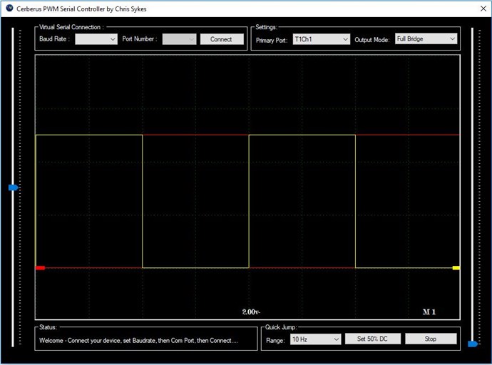
The main contributing reason (besides negligence) of why I think I blew a channel is because I still can't see what's going on using the scope.

I wanted to start this post by saying I made progress. I expect to still need to spend time getting to the point where I can light a light as a transformer. Troubleshooting that probably doesn't belong here.

When you say ground lift plug, do you mean these?

Is this an example of how I would connect the Ground of an unused channel to the lift plug? I will try this later too.

Overall I'm extremely grateful for your thoughtful comments and that I got something to work, but understand that I need to re-read your latest troubleshooting steps when I'm on the bench. There's more to learn from those comments.

I did end up connecting the Honda Generator. The circuit still worked and I did see less noise when probing... but I'm still not doing something right if I can't see the signal coming out of the MCP1403 of a working device

I'm almost to the point where I can start to spend time tuning the device itself. You can expect those questions to go in their relevant post by topic.

thaelin posted this 05 June 2023

Hey there:

   Just for the record, I am now coming up along side of you with a amcc 0400 and 200 turns l2 and l3. Figure 20 turns for l1. Long time trying to use what at hand and didn't work as I wanted. Will be starting my own thread but wanted to give encouragement any way I can.

thay


donovan posted this 07 June 2023

Hi,

Yes, that is just the ground lift plug I use!

When grounding the scope, use only the ground clip at the end of the scope probe.

99.99% of time when using multichannel scopes, I will remove the ground leads from all the scope probes except Channel One, (which would be my trigger channel......)

It is more important to have no ground loops as opposed to maybe a little bit more noise on the other channels.

I have trained a few people in my time......and I think it also is more important, to just put up with a little noise.....rather than be lead down the garden path by accidental ground loops.

Grounding by itself is a life time of learning to understand all the nuances.

Great job!!!

Donovan

Kritischer posted this 07 June 2023

Thank you all again tremendously for the thoughtful comments and guidance.


I have had repeated success using the 2nd (top) channel.

I changed diodes, resistors, and the RK0515 on the bottom most recently. 

Now that I know where to probe across easiest (pin 1 of IL610 and one side of 1kΩ off pin 6) the signal presence is obvious and clean. I'm now positive (or have at least convinced myself) that I damaged the other IL610's. I should probably swap the one from the top, but I hate these chinsy dip sockets and don't want to push my luck. I ordered more IL610's expedited because I need at least 2 channels this time around.

I had the setup ringing last night while trying to light a bulb as a regular transformer. I didn't get there yet but the switching definitely works and the rise times are < 20nS. I saw upwards of 140V p2p from a 4.5V input from the PS. I need to get better at taking scope shots for my next post, which may be here or somewhere else on the forum. 

Tinker posted this 27 January 2024

Hi all, @Chris, just wondering if you have gerber files for the lastest switching PCB or happy to purchase if you still have some available? I read through this thread a couple of times and watched most of the videos however please excuse my ignorance with the next few questions/clarifications as I’m still pretty new to this.   So if I understand correctly the board has a power supply of approx 5V to run it’s circuit, it takes a PWM signal from any function generator source (Ardunio or dedicated Function Generator), and switches an external power supply based on the PWM signal. 

So;

  1. Does it switch positive and negative from the power supply? From what I could see in one example you were  switching the negative only.
  2. Is there a max voltage and/or current that can be switched?
  3. Is there a max frequency for switching?
  4. You mentioned this is 4 channels, do we need all 4 for our experiments or is this just for redundancy/backup?

Thanks in advance. If this is not relevant to this thread please IM me.

Neale

  • Liked by
  • Augenblick
Chris posted this 27 January 2024

Hi Neale,

Gerbers are attached to this thread, you will need to read through the thread.

Both High Side and Low side switching can be done.

The rest depends on your application, what mosfets you put in.

Best Wishes,

   Chris

  • Liked by
  • Augenblick
  • Tinker
Tinker posted this 28 January 2024

Ooops, rookie mistake on my part. I saw the post box at the bottom of page 1 and thought that was it. My apologies, am continuing to read. Lesson learnt!


Neale

  • Liked by
  • Chris
  • Augenblick
Phil posted this 28 January 2024

Hi Neale,

I can send you a PCB for free as I have a spare.

PM me your address and I'll send it ASAP.

I can probably add some components with it as well.

Cheers,

Phil

Tinker posted this 20 February 2024

Good afternoon from Australia,

Now that my 4-channel switching setup is built and operational I've begun replicating simple experiments and thoroughly enjoying the process. Having already gained a lot of knowledge, I decided to revisit some videos in search of fresh insights. During my viewing of "Non-Inductive Coil Experiment - Video One" by @Chris, the Capacitor Protection Block was mentioned, prompting me to quickly recognise that it's cheap insurance for my power supply.  I have looked around the internet for ideas and I'm hoping some members can lean in with what they use and perhaps offer some circuits.  Thanks in advance.


Neale

PS -  I have 4 spare circuitboards available if anyone would like them, no charge. @Chris perhaps you can assist in allocating them or is it first to IM me?


This is the Capacitor block. - looks straight forward but just want to confirm. Thanks again

I need this

Chris posted this 21 February 2024

Hey Neale,

Sorry for the late reply, been busy.

The Capacitor Array and Protection Diodes are not important, but yes they can:

  1. Protect your Power Supply.
  2. Show, that Power coming back does occur by Blocking the returning Power, via the Diodes.
  3. Change the state of operation of your machine.


You need to be careful with these sorts of things, because a simple Cap Bank and Diodes can change the operation of the whole Circuit, which can throw you off track, so beware of this!

Its a very simple circuit, here is a pic of the PCB:


Pretty straight forward.

Best Wishes,

   Chris

We're Light Years Ahead!
Members Online:
What is a Scalar:

In physics, scalars are physical quantities that are unaffected by changes to a vector space basis. Scalars are often accompanied by units of measurement, as in "10 cm". Examples of scalar quantities are mass, distance, charge, volume, time, speed, and the magnitude of physical vectors in general.

You need to forget the Non-Sense that some spout with out knowing the actual Definition of the word Scalar! Some people talk absolute Bull Sh*t!

The pressure P in the formula P = pgh, pgh is a scalar that tells you the amount of this squashing force per unit area in a fluid.

A Scalar, having both direction and magnitude, can be anything! The Magnetic Field, a Charge moving, yet some Numb Nuts think it means Magic Science!

Message from God:

Hello my children. This is Yahweh, the one true Lord. You have found creation's secret. Now share it peacefully with the world.

Ref: Message from God written inside the Human Genome

God be in my head, and in my thinking.

God be in my eyes, and in my looking.

God be in my mouth, and in my speaking.

Oh, God be in my heart, and in my understanding.

Your Support:

More than anything else, your contributions to this forum are most important! We are trying to actively get all visitors involved, but we do only have a few main contributors, which are very much appreciated! If you would like to see more pages with more detailed experiments and answers, perhaps a contribution of another type maybe possible:

PayPal De-Platformed me!

They REFUSE to tell me why!

We now use Wise!

Donate
Use E-Mail: Chris at aboveunity.com

The content I am sharing is not only unique, but is changing the world as we know it! Please Support Us!

Thank You So Much!

Weeks High Earners:
The great Nikola Tesla:

Ere many generations pass, our machinery will be driven by a power obtainable at any point of the universe. This idea is not novel. Men have been led to it long ago by instinct or reason. It has been expressed in many ways, and in many places, in the history of old and new. We find it in the delightful myth of Antheus, who drives power from the earth; we find it among the subtle speculations of one of your splendid mathematicians, and in many hints and statements of thinkers of the present time. Throughout space there is energy. Is this energy static or kinetic? If static, our hopes are in vain; if kinetic - and this we know it is for certain - then it is a mere question of time when men will succeed in attaching their machinery to the very wheelwork of nature.

Experiments With Alternate Currents Of High Potential And High Frequency (February 1892).

Close