The MEG - Tom Bearden

  • Topic Is Sticky
  • 4.1K Views
  • Last Post 15 March 2023
  • Topic Is Solved
Chris posted this 01 August 2017

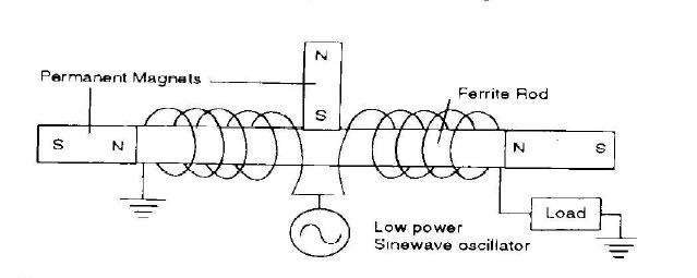
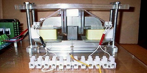
Tom Bearden's MEG, Motionless Electromagnetic Generator, is fairly old. Patent issued March 26th 2002.

Many say The MEG doesn't work. I can tell you, it does work when replicated properly!

Its a case of Understanding what to aim for, and replicating it properly. Which is very hard when some data is intentionally withheld!

Well, several discussions have bought the MEG up, so this Thread is for MEG Discussion.

I recommend visiting the Timing Thread for some information

When Tom Bearden used the term "Non Linear", this term meant Timing. Timing of the Coils, the Interactions between them and that it was very important to make sure the MEG was Non Linear in this way!

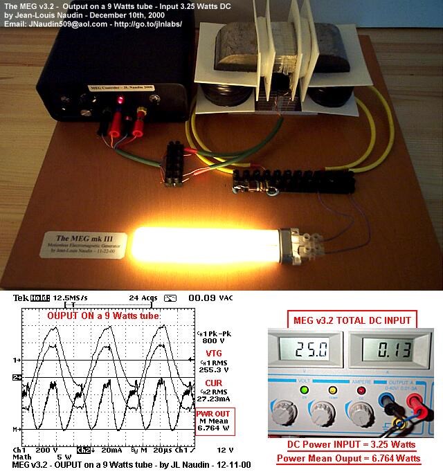
It took me a while to understand this. Something I read on the JLN website put me in the right direction:

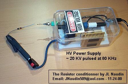
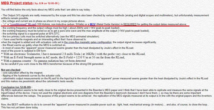
a MOV (Metal Oxide Varistor) is REQUIRED for getting the output datas measured above

- JLN Labs - The MEG Project

Now for some here, this may make sense. But for others, I was one of these ones, I needed a bit more information.


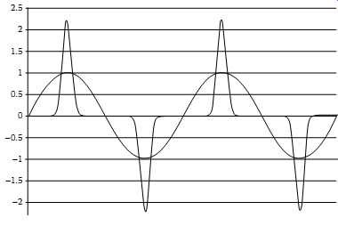
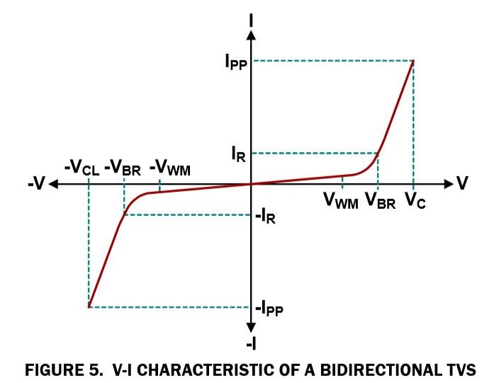
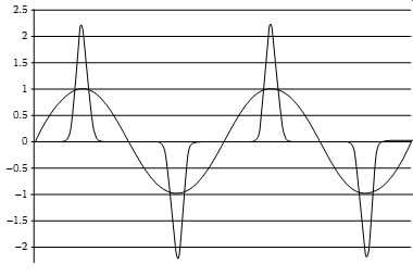
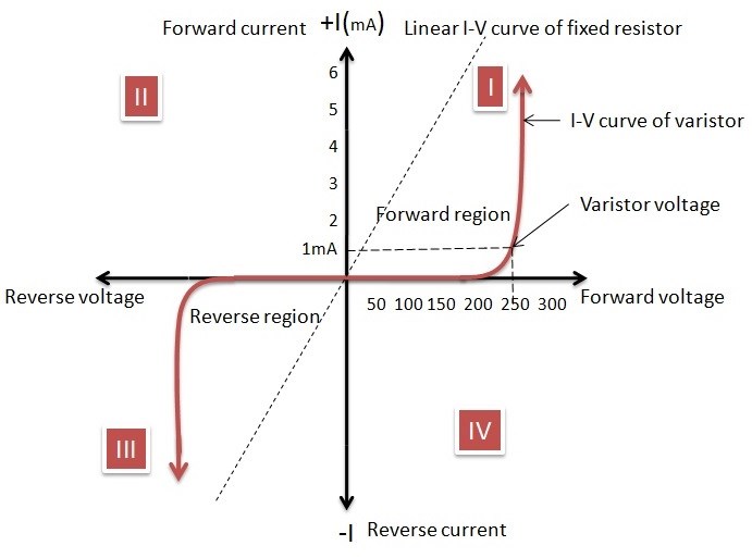
A MOV is non Linear, meaning that is is an OFF device until a Voltage Potential is reached. At this point, the MOV Conducts, is now On, it becomes a Switch if you like, a Voltage Controlled Switch!

Above, the Diagram depicts a MOV that starts Switching On at around 250 Volts, it conducts at 250 Volts!

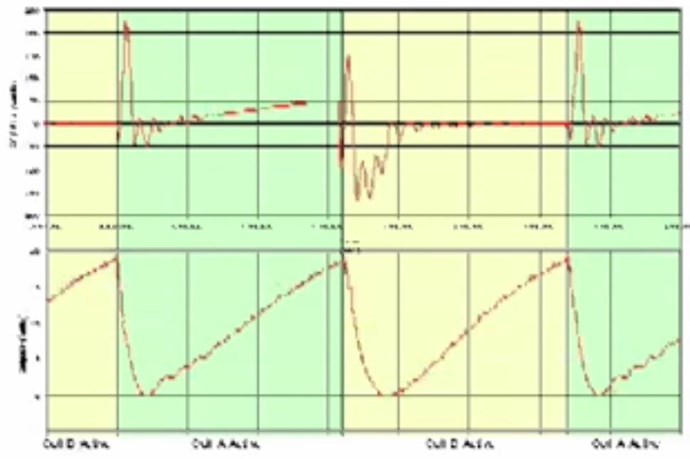
So Conduction might typically look something like this:

Note: This wave form does not apply exactly to the MEG.

All MOV's are Rated, have different ratings, and ratings can be very different. Some voltages might be 18 Volts. So make sure you know what youre using!

So the Timing here, it is again what we saw before. It is sensible! There is a Timing at a particular Voltage, this Voltage triggers Interactions Between the Coils on the Core at this time!


   Chris

Order By: Standard | Newest | Votes
Chris posted this 15 March 2023

Hey Donovan,

Why delay the Conduction? What's the delay for?

  1. Input Coil Switches On, applying a Voltage across the Coil and the Current Ramps up: T = L/R seconds. 
  2. The Secondary Coils, Plural, each see a Magnetic Field changing in Time: T = L/R seconds. A Voltage will be "Generated" on the Terminals of each Secondary Coil. A Current will Flow if the Coils are loaded, and if the Coils are not in an Off State!
  3. Of course, a MOV, or a Diode, or "Using a Transorber ( Transient-voltage-suppression diode )" will Create a Delay, and the Coil will only move into an On State, when the Device Used moves into an On State. The strongest Magnetic Field will be its Source. Polarity Matters Here!


So the Secondary Coils Buck Each Other, at a Resonant Frequency, and the Device, a Diode or whatever, creates a Delay in Conduction.

Its very very simple once one actually understands this concept.

We must think in terms: Every Coil that has a Current Flowing, has an associated Magnetic Field that Changes in time! This means, each Coil can be a Source for another Coil. This becomes Asymmetrical Electromagnetic Induction.

Currently all Power Systems are Symmetrical! Symmetrical Systems can never be Above Unity because: Output = Input - Losses!

Asymmetrical Electromagnetic Induction does not work this way! Output = ∞ Because we are not limited by the Magnetic Field, we are only limited by the Design and Geometry. The Magnetic Field does not have any Limit that we know of.

45.22 Tesla

Scientists in China have set a new world record for the strongest steady magnetic field ever generated on Earth. The hybrid magnet managed to produce a field measuring 45.22 Tesla (T), which is over a million times stronger than the planet's own.

Ref: World's strongest steady magnetic field generated in China


Limited only by the Technology we currently have available.

Study the Bucking Magnetic Field: Magnetic Field Pressure!


What is Going on here? This Video is completely Symmetrical, how do we make it Asymmetrical?

Because all Magnetic Fields Changing in Time is a Source for Electromagnetic Induction again, twice on one System!

The ONLY way to increase the Output over the Input Coil is to have a Gain in Electromagnetic Induction on the Output Coil, this is Asymmetrical Electromagnetic Induction, where more Electromagnetic Induction occurs in a System than the Input Coil Allows for!

Thus; An Above Unity Energy Machine! Very very Simple! But, the Dumb Dumb Club cant see the Forrest for the Trees!

You can see exactly this in the Spoiler Alert on the Home Page!

Best Wishes,

   Chris

donovan posted this 15 March 2023

Hi,

Been doing more reading on this website, than lab work, lately, but that's OK.

MOV - delayed conduction - to allow for Di/Dt to effortlessly create the needed Voltage on our coils.

Donovan

  • Liked by
  • Augenblick
  • ISLab
Chris posted this 14 March 2023

My Friends,

Seems there is quite some confusion in the Community, some confusion that comes from a very poooooor Understanding of Electrodynamics and Engineering!

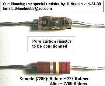
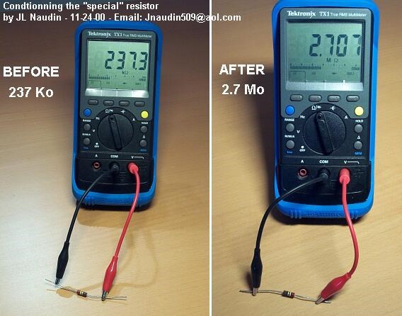
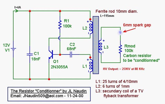
Some are focusing on JLN's "Conditioned Carbon Resistor" - Method for "conditionning" a carbon resistor


This is a very poor avenue to focus on, and an avenue that is totally mute in this field! Its a poor excuse that holds no water! JLN gave you this advice:


Which we have covered many times on this thread for a very good reason! What is a MOV? Is anyone paying any attention?

Distraction, and then lead you off a cliff is what they are trying to do!


Why did JLN do this experiment? To prove something? Most likely! What did he Prove? What did JLN Observe? Why go to such an extreme when one can buy a MOV for a few dollars? I believe JLN will tell you, you're wasting your time focusing on non-sense!

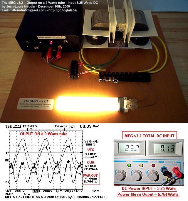
What did the RLoad do:

Ref: JLN The MEG.


Perhaps a better area to focus on would be: Delayed Conduction in Bucking Coils but hey, what do I know, I have not helped many many people reach a boundary in Science that no one could reach before! Or have I?

Focus on Polarity and Magnetic Field Interactions, because that is where everyone should be focusing, not on Non-Sense all the time!

Oh the Desperate Non-Sense! A bad Social Engineering Experiment and you're the Lab Rat!

Best Wishes,

   Chris

Prometheus posted this 25 February 2019

In about 3 weeks, I get my FeNi wire, then I can start experimenting. I've still got to buy the pieces to build my function generator / amplifier / power supply (I'm putting them all in the same case). I'll be doing that while I wait for the wire.

Chris posted this 25 February 2019

@Prometheus,

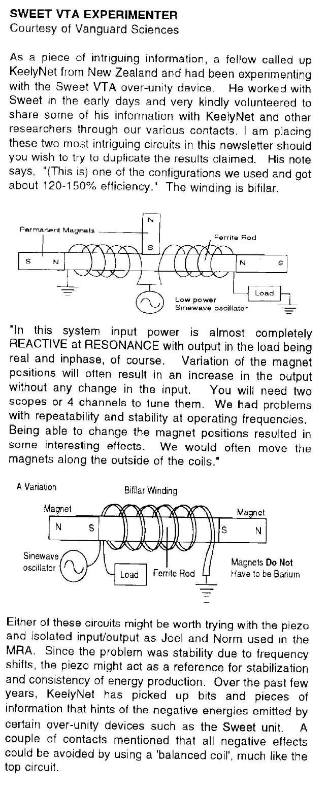
I had a little giggle there. Does this image remind you of The MEG:


The MEG is, weather parties like to admit it or not, the same in every aspect, Floyd Sweet was the father of The MEG.

   Chris

  • Liked by
  • ISLab
  • Augenblick
Prometheus posted this 25 February 2019

@All - Prometheus is right!

I want to point to the last video released:

At time 12:00, they state that they get power out of the steering coil which isn't energized.

That's very good news for those wishing to use a parametric oscillator to power both coils in series with alternately opposite polarity.

Think of a tank circuit oscillator which swashes current back and forth, except the inductor is adding a bit of energy with each iteration... that means this device could conceivably be self-powered from the get-go. At the very least, it's going to require a minute amount of external power to keep the steering coils operating (accounting for losses and assuming the energy added from the non-active-side steering coil is minimal).


Chris posted this 24 February 2019

@All - Prometheus is right!

I want to point to the last video released:


Specifically at: 15 : 16

The Image we all should be getting fairly familiar with now:


Perhaps Scope probes or Data plotted is in reverse?

Using a Transorber ( Transient-voltage-suppression diode )


There is no secret left un-solved, its all out in the open. Magnetic Resonance, the MEG does it also when implemented correctly.

What does the Transorber do? That's right, its a Delay in Conduction!


Yes, we truly are Light Years ahead of the other forums!


   Chris

  • Liked by
  • ISLab
  • Augenblick
Prometheus posted this 24 February 2019

A couple notes:

The MOV:


The MOV is used to generate a sharp spike of current and hence a sharp peak of magnetic flux. This is necessary because we're not using the transformer core in the traditional manner, which I discuss below. There are ways around that, though.


The Steering Coils:


The typical steering coil is solenoidally-wound, and thus must 'pinch' the magnetic flux in the core, thereby increasing reluctance in that path. This indirect method of increasing path reluctance requires more energy.

We are building variable-reluctance devices, so we must find the most efficient method of varying path reluctance.

Because of the solenoidally-wound steering coils, the opposite flux path typically will not get much of an assist from its steering coil, and in fact, could have its flux path through the core 'pinched' (and its reluctance increased), as well, defeating what we're trying to accomplish.

This is why my design will have spirally-wound ferrous-metal steering coils in-line with and acting as part of the magnetic circuit.

The ferrous metal of the coils have just slightly higher coercivity than the core, so when the magnetic domains in the ferrous wire are aligned by an electrical current running through the wire, the magnetic flux from the permanent magnet will follow the path of least resistance and go through the opposite flux path (especially considering that the opposite flux path will have its steering coil assisting the flux). This occurs with just enough electrical current to flip the domains in the ferrous wire, requiring on the order of millijoules. The current can be quickly pulsed to the steering coils, then shut off, and the steering coil magnetic domains will remain aligned such that they're steering the permanent magnet's flux to the desired flux path, until the steering coils are pulsed again with opposite polarity, akin to a magnetic 'switch'.


Traditional Transformers:


The way a traditional transformer works depends upon domain flipping (and thus the eddy current in the core). We don't do that. We merely pulse the magnetic flux unidirectionally, we never flip the magnetic flux vector.

Again, it's the solenoidally-wound nature of the windings. They build them that way because it's cheaper, faster and easier... not more efficient.

The primary coil of a traditional transformer has a sinusoidal current which causes spin-flipping of the valence electrons in the primary coil, which causes their magnetic field to sweep across the core, setting up a similar sinusoidal current in the core (eddy current), causing a similar spin-flipping in the valence electrons of the core material, which then cuts the secondary winding, setting up a similar sinusoidal current in the secondary winding.

This is the reason current lags voltage by 90 degrees in a transformer, and the reason secondary voltage lags primary voltage successively more as secondary load increases.


The Variable-Reluctance Transformer:


Because in our devices we're switching the flux and never reversing it in each flux path (no domain flipping), we're not going to get much 'sweep' of the valence electron's magnetic fields across a solenoidally-wound coil... we're only going to get that sweep making up the difference between the core's remnant magnetization (when the permanent magnet's flux is not traversing that flux path) and its full magnetization (when the permanent magnet's flux is traversing that flux path), not the full 'sweep' caused by a magnetic domain reversal.


The Output Coils:


The answer to this is to create toroidally-wound coils for the output coils.

To visualize this, imagine taking a winding bobbin and cutting off the flanges on each end. Then you wrap the wire through the center of the bobbin, creating a toroidal coil along the length of the bobbin. Then you place the bobbin lengthwise in the magnetic circuit. The wire would be wrapped sufficiently to fully fill the bobbin interior, and since it's ferrous wire, it'll act as its own core.

Think about how a Tokamak reactor works:

The primary winding can be anywhere on the transformer yoke.

Because a toroidal coil concentrates all its magnetic flux within its core, it doesn't appear at first glance that a changing magnetic field in the inner diameter of a toroidal coil would induce a current in the toroidal windings... except the changing magnetic field in the inner diameter of the toroidal coil has curl, thus current density is produced in the toroidal windings, in accordance with Maxwell's Fourth Equation.

All magnetic fields must have curl, and the curl of a magnetic field at any point is proportional to the current density at that point, per Stokes Theorem.

curl B = 4πJ / c  Where: J = current density

An additional benefit to this is that it's somewhat akin to the opposite of a Field-Reversed Configuration magnetic confinement for fusion...
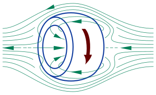
You'll note the inner magnetic field in a Field-Reversed Configuration bucks the applied field... but in our setup, we're only putting the applied field through the center of the toroid, thus it won't buck. There should be no bEMF.

As James Clerk Maxwell stated in 1861:

"Let there be a circular ring of uniform section, lapped uniformly with covered wire. It may be shown that if an electric current is passed through this wire, a magnet placed within the coil of wire will be strongly affected, but no magnetic effect will be produced on any external point."

And vice versa... the coil will be strongly affected by a changing magnetic field within the inner diameter of the toroidal coil. But a changing magnetic field outside the outer radius of the coil will have little effect.


Thus we have the most efficient means of flux-switching, and the most efficient means of converting the changing magnetic flux from the permanent magnet into electrical current.

This is the reason I've spent so much time looking for the right iron-nickel (FeNi or NiFe) wire for my design.


Additional reading material:

https://commons.vccs.edu/cgi/viewcontent.cgi?article=1084&context=exigence


Chris posted this 22 November 2018

My Friends,

A very important video corroborating information above Information:


Thanks to Atti for sharing this video.

Keep in your mind NON-Linear Inductance! Also, research Jim Murrays Transforming Generator:


I have also shown these Effects in my PDF and here: Reduced Impedance Effect

I don't agree with everything that Jim Says, but the actions in the Coils between the two devices are the same, whence the MOV's do their job at Top Dead Center ( TDC )

   Chris

Chris posted this 10 August 2017

Tom Bearden has done a lot to get information out to people.

However, his work, or I should say, what he has learned, has been patented to the teeth!

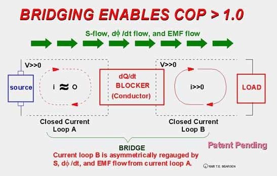
What would "Current loop B is Asymmetrically regauged by S, dPhi/dt, and EMF flow from current loop A" mean? Yes, we already know!

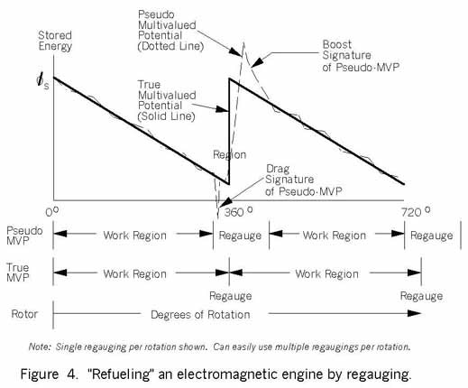
Tom Bearden's Regauging is a very technical way to describe what we know above:

Note, its hard to read, but Patent pending: 1995, this is the year Floyd Sweet died! Tom Bearden's MEG is the same tech as Floyd Sweets early work, it is shown slightly differently:

.

Nanocrystaline instead of Ferrite, Actuator Coils instead of driving from the Power Coils, but the device is the same.

The Asymmetric Loop mentioned above, is simply the timed Shorting, Magnetic Field Interactions at the right time!

Secrets are to the detriment of Mankind!

   Chris 

Chris posted this 03 August 2017

Hi CD, Yes Sir, that's right. This Interaction, the Timing and the Duration of it, and the entire device's geometry needs to be taken into account, but yes basically this is exactly right!


Asymmetrical Magnetic Field Interactions is the Key, or Non-Linear Interactions:


Stress, the term used by Tom Bearden, is the definition for a Scalar Wave. This is the Magnetic Compression and Decompression in Time:


This may make more sense now, now we know what "Choking Off" the Input means.


We know exactly how this works. Its just a case of "is the theory right" and helping others understand all this.

   Chris

  • Liked by
  • Augenblick
Chris posted this 02 August 2017

Hi CD, yes, this is right!

The MEG does work! Imagine what's happening in The MEG to all the Coils:


Note: Look at the top of the JLN Power Wave Form. What do you see?

Imagine One Coil only, the one with the Carbon Resistor, that is a MOV, because of the Magic JLN did to the Resistor...

This Coil is Open Circuit, until the MOV Conducts and shorts the Coil, this is at the MOV's rated Voltage! Remembering this Coil the Voltage and Current will be in Phase, because we have a Resistive Load! So when the MOV Conducts, which will be a Short, the Magnetic Field Bucks, at its Max Field Potential.

All this time, the other Coil is powering a Load, standard electromagnetic Induction is Occurring, but then at peak, this coil sees a Huge Hit of Magnetic Field! From the Other Coil.

At the same time as this Hit, the Input Coils get a blast and this reduces the total Input, or in some cases fry's the Input Circuitry...

This, for Free, we see a huge gain in Electromagnetic Induction, because we have it occurring more than once in the System!

Thus the reason for the Timing Thread.

   Chris


Chris posted this 01 August 2017

Hi HDZeddies, I don't want to dissuade anyone from what they are already doing. I don't want to do that. We all have our own path. We all have our own way of doing things.

So I recommend to all, do exactly what you feel is best.

If I can help though, if you're looking, and if you see what I am sharing may be of use, then I am more than happy also. If you see the link to Partnered Output Coils, then I have laid out all I know here in these pages. Lets make sense of what decades of History hasn't!

I am a little bit of a stickler for Notes, I take notes much of the time, its how I keep track of things. However, as I learn more, I understand more, so I am not always right. Sometimes I see things cloudy until the Cloud clears.

If you want to see an Excess in Electrical Energy, then we must understand Electrical Energy and how it is bought about! Electromagnetic Induction!

The very definition of the name: The Motionless Electromagnetic Generator, does in-fact say all we need to know! The MEG is a "Generator", solid State. It takes advantage, just the same as a Hydro Electric "Generator" does, of the Laws of Electromagnetic Induction. Its difference is that this device, the MEG is Asymmetrical, not Symmetrical like the Hydro Electric "Generator"..

The key is in the Magnetic Field Interactions!

I worked from the JLN Replications, my Project was here: The MEG Replication Project

I got so far on the project publicly, and then did not publish after some average results. Later I attempted again, with a smaller version, and got better results. This was after I learned much more, after I understood some things I needed to aim for.

You will see, the JLN Replications were as I found, not much success at the start, then progressing with persistence!

I still recommend the JLN Replications. That's what mine were based on. Originally, I missed some information, this is the problem! This information I missed, I covered in the Timing Thread, because Timing makes a Device Asymmetrical!

I hope this helps!

   Chris


  • Liked by
  • HDZeddies
  • Augenblick
HDZeddies posted this 01 August 2017

Hi Chris, 

Thanks for opening of this new topic. 

What I want to point out is, that I have seen on my own replication, that the input coils are working really good in special frequencies. If you can reach this, they will work as blocking for one half of the double C core and the magnetic flux of the permanent magnets will be channeled to the other side. If the switching changes it runs vice versa in the other direction. 

I have observed, that an increase of voltage in the input coils had no increase on the output side. So the coils are working only as blocking magnetic wall.

I have seen the thread Timing but I will read it again. there are interesting ideas.

In my replication I winden the input coils in bifilar mode. Now I want to make new generator coils. I want to understand completely the partnered coils, what I actual don't.Or are there other ideas to wind the generator coils of a MEG?

HD

  • Liked by
  • Chris
  • Augenblick
We're Light Years Ahead!
Members Online:

No one online at the moment


What is a Scalar:

In physics, scalars are physical quantities that are unaffected by changes to a vector space basis. Scalars are often accompanied by units of measurement, as in "10 cm". Examples of scalar quantities are mass, distance, charge, volume, time, speed, and the magnitude of physical vectors in general.

You need to forget the Non-Sense that some spout with out knowing the actual Definition of the word Scalar! Some people talk absolute Bull Sh*t!

The pressure P in the formula P = pgh, pgh is a scalar that tells you the amount of this squashing force per unit area in a fluid.

A Scalar, having both direction and magnitude, can be anything! The Magnetic Field, a Charge moving, yet some Numb Nuts think it means Magic Science!

Message from God:

Hello my children. This is Yahweh, the one true Lord. You have found creation's secret. Now share it peacefully with the world.

Ref: Message from God written inside the Human Genome

God be in my head, and in my thinking.

God be in my eyes, and in my looking.

God be in my mouth, and in my speaking.

Oh, God be in my heart, and in my understanding.

Your Support:

More than anything else, your contributions to this forum are most important! We are trying to actively get all visitors involved, but we do only have a few main contributors, which are very much appreciated! If you would like to see more pages with more detailed experiments and answers, perhaps a contribution of another type maybe possible:

PayPal De-Platformed me!

They REFUSE to tell me why!

We now use Wise!

Donate
Use E-Mail: Chris at aboveunity.com

The content I am sharing is not only unique, but is changing the world as we know it! Please Support Us!

Thank You So Much!

Weeks High Earners:
The great Nikola Tesla:

Ere many generations pass, our machinery will be driven by a power obtainable at any point of the universe. This idea is not novel. Men have been led to it long ago by instinct or reason. It has been expressed in many ways, and in many places, in the history of old and new. We find it in the delightful myth of Antheus, who drives power from the earth; we find it among the subtle speculations of one of your splendid mathematicians, and in many hints and statements of thinkers of the present time. Throughout space there is energy. Is this energy static or kinetic? If static, our hopes are in vain; if kinetic - and this we know it is for certain - then it is a mere question of time when men will succeed in attaching their machinery to the very wheelwork of nature.

Experiments With Alternate Currents Of High Potential And High Frequency (February 1892).

Close