My Notes on Floyd Sweet

  • 2.5K Views
  • Last Post 25 October 2021
DoofusNugget posted this 22 September 2021

Hello, this is my first post on this website so hopefully the context of this post is on the correct category. Anyway, I'm attaching a document to this post. Its a rough draft of essentially planned details, pictures, and ideas on the chronology of Floyd Sweet's work. It is currently not complete, it is in a very early form, but some stuff is already written, so take a look if you'd like. Hopefully, it'll give inspiration or ideas to those who read it or desire to look into the details of Floyd Sweet's devices, but again, it's still incomplete at this time.

I also have not been able to get access to all of the material out there regarding Floyd Sweet, although I have most of it. I have not seen the "Floyd Sweet Memories" video which came out many years ago, and I don't have some of the  original copies of Sweet's papers (not the one's which were translated on this website, but the original handwritten one's and some typewritten ones back in the day).

Feedback will be appreciated, and calculation mistakes I may have made I'd appreciate feedback on that. In the future, I'd hope a document like this can serve as a reference for myself and others interested in Floyd Sweet, so the information is all in one place, easy to access. Enjoy!

P.S. I'd like to emphasize I don't consider myself currently having the capabilities to perform experimentation like others on this forum, to the level I have seen over the years. But, hopefully I can give ideas to others who are more capable than me in some ways at this point in time, and bring forward inspiration or support.

Order By: Standard | Newest | Votes
Chris posted this 25 October 2021

Hi DN,

This forum is a Builders Forum!

I feel at this stage, that if you are not going to share experiments to prove your theories, then I will be forced to close and remove this thread.

This Thread is becoming more and more misleading to other readers.

I refuse to be part of the Propaganda Machine!

Regards

   Chris

  • Liked by
  • Shadow_
  • ISLab
DoofusNugget posted this 25 October 2021

The Modulation of Space Quanta:


I write this post emphasize on how the flux is being modulated in the Space Quanta Modulator. I have made two crude diagrams to illustrate my point.

The little arrows in the second diagram I made represents the destructive interference of the magnetic fields. The point I am trying to make in the arrangement of the Space Quanta Modulator with orthogonal coils, when you have two perpendicular magnetic fields, the resultant field will be now at slanted/angled depending on the strengths of both of the fields.

What happens when you have two perpendicular magnetic fields as in the configuration of the Space Quanta Modulator, it somewhat mimics a rotating magnetic field.

And what happens when we have coil in a rotating magnetic field, we can get an induced electromotive-force. And a rotating coil in a steady magnetic field will also have an induced electromotive-force.

This is a path I'm taking regarding the back-engineering the SQM, I recommend others look into this type of flux-modulation too. I also have two patents that I found recently with very similar flux modulation principles and geometry to the SQM.

https://patents.google.com/patent/US20100308675A1/en

https://patents.google.com/patent/US8089188B2/en?inventor=Thomas+George+Thundat

However, the patents uses a core material which from my investigations, implementing a core (between the space of the permanent magnets) perhaps may kill the "power-gain" effect Floyd Sweet was getting in his device. The two patents also are in the form of an alternator, however I'm sure the patents can be used to derive what Floyd was originally doing with his ideas on the Space Flux Coupled Alternator. 


In that being said, I fully intend to attempt a replication of the SQM with my knowledge up to this point. I intend to use a 1-pound excitation coil for sufficient magnetic flux. Instead of alternating currents I will attempt to work with pulsed direct currents, and utilize frequencies up into possibly the multi-kilohertz range. Since the device works based off of Faraday's Law, increasing frequency will allow for an increase in output electromotive-force. For example, 10-times increase in frequency will increase the output volts by a factor of 10, but the output power will increase by a increment of 100. I will attempt to pump at least one ampere into the excitation coil as well, so with such factors we could see at least a coupling effect perhaps. I plan to employ a single power coil for now too. I have some parts coming in the mail, so I need to wait for those. I already have four 6 inch by 4 inch by 0.25 inches thick magnets. Perhaps it may be while once I get all the parts to share any results, so we will see how things go...

DoofusNugget posted this 25 October 2021

I'm going to post here some pictures and  diagrams of one of Floyd Sweet's self-powered units, diagrams from Walter Rosenthal specifically. If you look at the circuit and the pictures, it appears to be a perfect match. I have not seen these diagrams appear elsewhere, I will post them now so they are not lost and so people can consider the design evolution. I found them months ago (the coil specifications and circuit diagram) from one website, I copied them and have them on my files now. 

If you apply Ampere's Law and Faraday's Law to these pictures, you will get some interesting results. 


I would also like to point out that many people interested in the VTA/SQM falsely assume that, since one version of the Space Quanta Modulator used microamperes while running (Floyd's first successful device), then all other versions of the device only require microamperes to run, which couldn't be further from the truth. If you look at the above diagrams and do the math, you will see at least 2 amperes is being drawn from the secondary of the center-tapped transformer. Furthermore, the excitation coil in this device is bifilar (what I presume to be in additive mode such that the magnetic flux doesn't cancel from each element in the bifilar winding) and it splits the current evenly into each a 900-turn element of the bifilar coil. Other documents indicate Floyd was interested in getting the magnetic flux from his excitation coils up.

You also see here in Sweet's own handwriting (in the above picture), he is using Faraday's Law. Of course you will also see that 1 amp will flow in the each bifilar element of the above coil arrangement. You see that Floyd uses the bifilar coil to make the proper connections to the center-tapped transformer, and I speculate to increase the magnetic flux since the resistance of the coil becomes distributed in the bifilar configuration (thus the current will be greater). You will see a similar situation in the below picture.

Another one of Floyd's self-powered devices, notice how big the excitation coils on the outside are, they will definitely be a decent vessel of magnetic flux. You can also see the center-tapped transformer is used in this picture.

Here you also see 900 turns being used in excitation coils. I also have copies of a fax that Floyd Sweet sent to Mike Watson in 1992. It describes the excitation coils in one iteration having about 3750 turns, four times as many turns than Floyd's 900-turn coils.

Though there appears to be a discrepancy, since Floyd's first version only drew microwatts on the input. However I suspect that Floyd may have been using an initial higher current draw from his oscillator to get the necessary induced electromotive-force, then used signal diode(s) or some other hidden circuitry as a form of feedback to reduce the input power to the milliwatt-microwatt range. I recommend anyone ask themselves, why does Floyd have significant excitation coils on his device? The original name of the device says it all (before Tom Bearden was ever on the scene), the Space Quanta Modulator...

  • Liked by
  • ISLab
Chris posted this 21 October 2021

@All Readers,

@Kaos, yes, that's right!

I promise You: Permanent Magnet Conditioning is Propaganda!

My Recommendations:

  • Floyd Sweet measured Voltage and Current - Start here! What's required for Voltage and Current?
  • Read all Documents Here!
  • Make steps to prove Propaganda False! Never run with Propaganda!
  • Floyd Sweets background was Transformer Expert, follow this lead!
  • What does Floyd's VTA have in common with other machines?
  • What do other machines have in common with Floyds VTA?
  • List Key Points Floyd Sweet did make, that make sense! E.G: "Electromagnetic induction with no measurable magnetic field is not new"


Honestly, this is so simple, so easy, and so cheap, one just needs a little bit of knowledge! E.G: What is required for Voltage and Current? Experiments here, on this Forum show you exactly how to do this, its the start to opening the door on the Sweet VTA!

Others, well, they know nothing and have made Zero Progress, we have many Independent Replications, all that cannot be disputed!


This Forum and our Backup Forum, are the only forums in the world that have Answers to Energy Machines!


Ask yourself, why did Floyd Sweet say: 

Electromagnetic induction with no measurable magnetic field is not new.


Under the sub heading: "FIELD SUPER-POSITION AND THE VACUUM TRIODE"

Why did Floyd Sweet say:

The current and potential windings require relatively little power, and are applied in such a manner that rate of flow of moving charges may be accelerated beyond 1 ampere = 6.2418 electrons / second. Thus the duty factor of the copper changes. I2R Losses diminish and more charges drawn from the now coherent space field flow at a faster rate as current to the load. This means as more current is required by varying loads more feedback magnetomotive forces free more electrons from binding forces complimented by potential magnetic forces of the orientated, coherent space field. Thus a conductor that formerly had a temperature rise above ambient labelled as a factor of 10 would now operate at a temperature of 1.0. Thus the same gauge wire would carry 10 times more current at the same temperature.


Floyd Sweet was obsessed with Electrons and the Acceleration of them, so again looking at Voltage and Current and what exactly is required for these, is the first critical step to understanding the VTA!

Best Wishes,

   Chris

  • Liked by
  • Shadow_
  • ISLab
kaos posted this 21 October 2021

So probably no conditioning.

Important keys.

Lab Notes - Floyd Sweet 0017

Input + Output coils are orientated at 90 Degrees so that the output Currents do not couple with the
excitation coil

Lab Notes - Floyd Sweet 0016

A Vector Complementarity (he calls this unit a
“Vector Oscillator)

  • Liked by
  • Chris
kaos posted this 21 October 2021

I still think the SQM is genuin butt it shows Swetts chracter he culd lie his teet out.

  • Liked by
  • Chris
Chris posted this 21 October 2021

Ah ha, yes, there you go, Thank You Kaos:


Best Wishes,

   Chris

kaos posted this 21 October 2021

 Walt Rosenthal , says so on page.

  • Liked by
  • Chris
Chris posted this 21 October 2021

@Kaos,

Yes it is a document from the Tom Bearden Archive. I do not know where Tom Bearden got it from. I did ask years ago, but got no answer.

Best Wishes,

   Chris

kaos posted this 21 October 2021

That one is from Tom Beardens Web Page Floyd Sweet (cheniere.org) he  got it from Walt Rosenthal and he must got it from Sweet.

  • Liked by
  • Chris
Chris posted this 21 October 2021

Hello Kaos,

Approximately 60% of all the information surrounding the Floyd Sweet Legacy is Propaganda: Lies and Nonsense!

One must ask WHY? Why would so many people make up so much outrageous Lies and spread as Propaganda?

For me, it is obvious!

Floyd Sweet was Highly Trained! His work, what we can show, for sure, proves this!

Today, after all that has occurred in the Field of Energy, it is only the Ignorant that choose to stay in denial about Energy Machines and the paradox of the Conservation of Energy Laws! The Ignorant or the Propagandists themselves!

I wonder why?

Also, another Propaganda story, essential reading: 

Wikipedia co-founder says site is now ‘propaganda’ for left-leaning ‘establishment’


Why is the world full of so much Propaganda? Why has there been so many Lies that are SO EASY TO PROVE WRONG?

Some choose to stay in denial, a small few, others see through the Propaganda, majority, 90%, and the rest are the Propagandists themselves!

The thing is Kaos, a nickname that is somewhat of an interesting choice for this forum, building Energy Machines that go well Above the Unity Boundary is Cheap and Simple! Many here have succeeded to varying degrees.

I don't mind people being skeptical, but there is a big difference between Skeptical and Stupid! I wonder where Michael Faraday would have drawn the line between the two? Or Charles Proteus Steinmetz?


Or Nikola Tesla?

Best Wishes,

   Chris

kaos posted this 20 October 2021


Francis Bitter died  July 26, 1967 ???

Chris posted this 18 October 2021

DN,

If you were to read my pages, I have already shown all readers how to do it:

You just never know, we may end up on the same path as each other!


Its already been achieved, no one seems to notice this basic fact! Let me try to hold my tonge at the moment and see what you come up with...

Best Wishes,

   Chris

DoofusNugget posted this 18 October 2021

Hi Chris,


I get the considerations with the superposition principle, in Floyd Sweet's paper, "Nothing is Something". Though I'm a bit cautious about that paper, since it was around the time Floyd was putting disinformation out, and part of me feels that he made the paper to partially cloud the truth. I think I'm going in a slightly different direction to how the bifilar coils in some of his devices were configured, but I also think this whole issue depends on how the magnetic field is oscillating/moving in Floyd's devices. For example take the below circuit diagram from Rosenthal:

I used to think the black arrows indicated the polarity of the magnetic fields, however I don't think that's the only way to interpret the diagram now. It could be more likely the arrows are just indicating current flow, since many of the winding of aren't specifying their winding direction, by the dot convention at least. Especially considering the connections with the center-tapped transformer with the excitation windings. I don't think it's totally out of the question Floyd could've used bifilar coils in "bucking configurations" in some of his devices, but perhaps it may not be necessary to get a device working. If I am wrong, then I am wrong, those are just a tiny bit of my current thoughts on that. But I'll need to think about it more, I suppose.

At the end of the day, I guess it's a matter of experimentation. I'm currently considering a crude setup to test experimentally, as I have succeeded in deriving mathematical correlations that Sweet was definitely using Faraday's Law in his device several days ago. I used only Faraday's Law, "Ampere's Law for Solenoids", and historical notes directly from Walter Rosenthal to determine this. I have also found a two very interesting patents today which describe very similar geometry and principles like in the VTA. I am planning to make a push on attempting to replicate the VTA to at least a small degree, with the setup I am considering at the moment. Perhaps something interesting will happen, or perhaps not. I will elaborate more on this in a second post.

Chris posted this 04 October 2021

I understand the issue with electromagnetic induction in Floyd's machine, if the whole magnetic flux movements. If you sweep a whole field across a coil, then you wouldn't get a significant net electromotive force, since emf is being induced in the other half of a winding against the emf in the first half. I have focused on mostly on simplest iteration of Sweet's device, with one output and one input coil, not with the bifilar arrangements.


Hi DN,

I am sorry, you only have this, partly correct. More investigation is required here.

Also, you need to understand the Bi-Filer Coils, its very important you do! If this is not understood, then one can not make any progress at all, with any of these machines! I can see you need to do more work here.

Floyd Sweet told us:

Electromagnetic induction with no measurable magnetic field is not new.

...

The principle of superposition states that; "In order to calculate the resultant intensity of superimposed fields, each field must be dealt with individually as though the other were not present". The resultant is obtained by vector addition of each field considered singularly. Consider for a moment the construction of the triode which includes the bifilar coils located within the fields of the two conditioned magnets.

When the current in one half of the conductors in the coils (i.e., one of the bifilar elements in each coil) of the device is moving up, both the current and the magnetic field follow the right-hand rule.

The resultant motional E-field would be vertical to both and inwardly directed.

At the same time the current in the other half of the conductors in the coils is moving down and both the current and magnetic field follow the right-hand rule.

The resulting motional E-field is again vertical to both and inwardly directed.

Thus, the resultant field intensity is double the intensity attributable to either one of the set of coil conductors taken singularly.

Expressed mathematically:

E = ( B x V ) + ( -B x -V ) = 2 ( B x V ) 


So one B x V is Negative? Why? How? Negative B? That's a -B? HOW? So we have a +B + -B? Bucking Coils? How did Floyd Sweet make a Negative B x V into a Positive B x V?

What relationship to a Triode does this text have? Again, What specifically is being Gated?

Ask the question: Why did Floyd Sweet use Bi-Filer Coils and when you have a good, solid answer, and you understand it, then the rest of the VTA makes sense!

Do you see why I am asking you these questions? Do you see what the really important points are? Do you see why I can so confidently dismiss "Conditioned Magnets"? Its a definite Lie and CIA Propaganda! Why was this pushed by so many people, and all the same basic story? Now proved to be a Lie!

Magnet Conditioning was a Lie told by someone that has a very poor understanding of Magnetics! Reason: It is very easily proven Fake!

Best Wishes,

   Chris


P.S: You seem like a Good Person! I am sorry I am being, what may seem like, Difficult! But please understand me when I say, my main battle was not the Trolls I have faced, it was the Propaganda, the multitude of Lies Told, so I am very firm about bringing the Lies out into the Light for all the public to see! Lies about such things have never helped Humanity! Why would anyone ever want to Lie about such things? Its Criminal!

P.P.S: The initial Learning Phase can be Steep, and Hard, but I will help best I can, always! That's why this Empire is here!

  • Liked by
  • Shadow_
  • ISLab
DoofusNugget posted this 04 October 2021

Hi Chris,


I understand the issue with electromagnetic induction in Floyd's machine, if the whole magnetic flux movements. If you sweep a whole field across a coil, then you wouldn't get a significant net electromotive force, since emf is being induced in the other half of a winding against the emf in the first half. I have focused on mostly on simplest iteration of Sweet's device, with one output and one input coil, not with the bifilar arrangements.

In terms of experimentation, I currently have limited resources when it comes to that. I really do not have much in terms of equipment, but I will see what I can do. Thus, I have mostly looked online and learnt that way. Hopefully, in the future I'll be able to show my experimentation, since I really do not have much to do that with currently. Thanks.

  • Liked by
  • Chris
  • Shadow_
Chris posted this 03 October 2021

Hi DN,

I think we need to see your experiments, showing what is really possible.

Do you know Why Floyd Sweet used Bi-Filer Coils?

Electromagnetic Induction cannot occur if the Uniform Flux of the Permanent Magnet Sweeps across the Coil's entire Surface - It is an impossibility and when you work out why this is, then your posts will start making more sense to Readers.

Guessing is a start to the process, I get that, but I suggest backing up your educated guesses with experiments so you do not fool yourself, and also others, this part is important above all else, into believing in Fictional Science as so many have in the past!

Have you read the threads here on this forum?

If so, you will have seen this image: Here.


Permanent Magnet Flux Modulation, for example, the "River Integrates into the Paddle Steamer's Engine Efficiency" simply because the Power Coils themselves, Modulate the Permanent Magnets Flux. I have shared this first image for a long time, all here are familiar with it, and yes the Permeant Magnets can aid, or add Energy to the System, only under some narrow, very limited, configurations. We have already done these experiments and some here have shown this type of possibility, one being L0stf0x.

That's why Walt Rosenthal said:

The VTA can be started by momentary connection of a 9 volt battery to the drive coils when the machine is operated in the self-powered mode.


Just like Tariel Kapanadze did! Coincidence?

We have proof, this is true and accurate, we saw this in the video!

Also, and importantly:

The operation is stopped by momentary interruption of power to the power coils.


Now, we see a very important quote, I have confirmed experimentally, from Walt:

The VTA "likes" to always see a minimum load of 25 watts.


Do you see now, why I tell people to stop believing in the Folk Tale of Magnet Conditioning? The Magnets themselves, had nothing done to them! Just try and get the Razor Blades to stand, they will not stand up unless very good quality Magnets are present:


Do you see why I have no patience for others that Speculate and do not put the work in to prove their Speculations? It only reinforces the Total Lies that have already been told! It is so obvious to others that have done the hard work and proven it all Fake!

I have put the pieces of the puzzle together, and I know what's possible, I know the entire Story, and most here, weather they consciously know it or not, they also have the pieces of the puzzle. I know who Lied, I know everything about the SQM / VTA.

That's why we have succeeded where others have failed! We have Above Unity Machines!

Please help stop the Propaganda Machine!

I do very much wish people would listen to Reason, follow Logic, and stop believing in Fairy Tales! 

Best Wishes,

   Chris

  • Liked by
  • Shadow_
  • ISLab
DoofusNugget posted this 03 October 2021

Hi Chris,


I understand the points you are making, I am very well aware of Sweet's comments in his earliest papers. However, I remain open to the fact that the magnets could've been modified in some way, just as I remain open to the fact the device could be operating without modification of the magnets. Do I believe there's some magical voodoo happening if they were modified, no, but rather modifying the magnets could simply aid in the operation of his device, which has underlining connections to the principles his early papers. I think it is more than obvious Floyd was focused on "flux modulation" principles for his machines, although I feel it is important to address, Sweet had laid out clear operating principles of his Mark 1 device, but not necessary Mark 2 in the same respects as of course he became deceptive after that.

But the fact that the device name doesn't change in the early days from the Mark 1 to Mark 2 device (the Space Quanta Modulator), illustrates there was a definite connection in each device's intended operating principles, I firmly agree to that and what you have pointed out. The lab notes from 1986 also seem to point to such a mode of operation. Of course, with the arrangement of perpendicular magnetic fields, you can modulate a magnetic field in principle.

It's important to note that Floyd's analogies presented to explain the operation of his idea for a device, was mostly for the Space Flux Coupled Alternator and the Static Space Quanta Modulator Mark 1, which both had slightly different arrangements compared to the Space Quanta Modulator Mark 2. One of the main things being the Mark 1 device had it's modulation coils and output coil parallel to the magnetic field, which I feel is important to take into account.

Perhaps the claimed results gotten from people like: Tom Bearden, Don Watson, Mike Watson, who all claimed to have gotten results with modified magnets, perhaps their results may have had nothing to do with modifying magnets, but rather due to coincidental parameters which resulted in some of their minor success. Maybe this is the case after all. I'm sure you understand I attempt to look at multiple possibilities.

I have seen some of your work regarding partnered output coils/bucking coils, I understand the thought process of attempting to introduce asymmetry into a traditional transformer to reduce the input. I'm not in complete agreement with some of the concepts out there on the internet regarding such things, but it is indeed a very interesting prospect to investigate, and if someone wants to experiment and find new things, good for them.

I believe the flux modulation principle at right angles to the magnets is a very promising explanation to Sweet's device (without magnet modification required), however there are still things that I feel have to be investigated regarding such an explanation, as some things to me still don't quite add up yet. That is why I turned back to the possibility of modified magnets increasing the effects of such a modulation effect, in other words portions of the demagnetized magnets increase the influence of the effect. However, due to such barium ferrite magnets having magnetic-hard properties, and the magnetization occurring perpendicular to the easy-axis of the magnets, then such an effect may not even be significant. Also, the measurements from the lab notes indicate the magnets were basically fully magnetized, which wouldn't leave much room for modification. So, perhaps I may be wrong regarding such a suggestion of modification of the magnets.

In conclusion, now that I look back on the evidence, it's probably more likely that the magnets were not modified, and anyone who got results with modified magnets was perhaps coincidental. The fact that such low input was on the Floyd's first device still stumps me a little bit (although the signal diode could help in lower the input to such microamperes), while it is obvious in his later devices, he definitely wanted to produce significant amounts of magnetic flux from his input coils, so I have no doubts that the modulation effect in his machine required sufficient magnetic field strength from the input. So I think I may be wrong in assuming modifying the magnets could help operate the SQM. However, I'm sure experimentation will prevail for anyone who decides to test the concept whether it be truthful. Thanks for making me think. 

Chris posted this 03 October 2021

Hey DN,

I have no problem if others have a difference in opinion, thats fine, all I ask, to save wasting Time and Effort, is to base opinions on Facts ONLY, put the specuilation with Zero Evidence asside.

All Readers should do this! All serious Researchers! If others are not prepared to do this, then I do not consider them a Serious Researcher.

One has to think like a Detective to find the Truth, because we all know there is a HUGE Amount of CIA Propaganda / Lies been told!

Can you prove, in any way, Floyd Sweets Magnets, in his Vacuum Triode Amplifier, were modified, in any way?

I can prove they were not!

Ask yourself: "Has any other energy machine ever needed Conditioned Magnets"? No, never, its Lies! Did Tariel Kapanadze need Barrium Ferrite Conditioned Magnets? No he didnt! Did anyone? No! Never! Its Propaganda!

The Magnetic Field making Electrons move in the VTA were not from any Permanent Magnet:


We have to closely Observe the Facts! The Magnets were not in Self Oscillation! No Readings on any of the equipment untill the HP Oscillator was switched on.

Floyd Sweet told us how the VTA Worked Here. Then he said, specifically:

The architectural configuration of the windings and their relationship to the magnets will be best understood by observing the construction of a prototype. 

The defining equations are similar to those of the dynamic Space Flux Coupled alternator. A working prototype should be ready about Easter.

Ref: Space Quanta Modulator - by Floyd Sweet P.H.D


The Magnets were depicted as a River, the VTA the Paddle Steamer, the analogy is clear! His confirmation of the different machines working on the same basic principles!

The working Model, the "Relationship":


Initially, this is difficult to grasp, study in Depth the Conventional Transformer, then ask why is it limited to a Symmetrical Machine?

Who has hidden away the Equations Floyd referrs to?

Best Wishes,

   Chris


P.S: I am sorry to be blunt and straight up, but I want Serious Researchers to have a clear path with no BS Propaganda in their path forward! Honesty is the best policy! Facts help Humanity! I am not trying to shoot you down, only help you find the Truth and prevent others being misguided by the continuance of the old propaganda machine.

DoofusNugget posted this 03 October 2021

Hi Chris,


I have no plans on spending any money on Floyd Sweet currently or even in the future, thankfully since experimenting sounds very expensive at times. I get what you're saying, I've known about your viewpoints on "magnet conditioning" for a few years before I joined your forum. Are there parts of the story involving Floyd Sweet which are questionable or maybe fake, yes. Is the output usable flowing electrons/current, yes, from an oscillating magnetic field in the device which can induce a net current flow. I know about the experiments you have done years ago attempting to replicate Sweet's device. I know about the experiments you have done in the past to reach the conclusions you have now.

However, from the historical record, we know particularly Walter Rosenthal helped build Floyd equipment for use in his research. There was coils with a capacitor discharge system (the one Rosenthal showed in the Seeking Overunity video), a device to tell how smooth a magnetic field was. At the very least, we know Floyd was using the equipment, whether involved in his device(s), or for something else. 

I do not rule out that the device could not operate without modifying the magnets in some way, in fact notice in one of my suggestions (suggestion 1) in my previous post does not require the changing of permanent magnets. At least to me, there are still some things that don't quite add up in that viewpoint as I have noted in my previous post, at least yet. Some things make more sense if the magnets are modified in some way, but some other things don't make sense in that viewpoint. I don't know, until someone has built an accurate working model, the scientific method right? It's something I need to think on regarding such two viewpoints to find a compromising solution for all the conflicting information out there on Sweet.

I will say this again as I have previously, do I think if the magnets were modified then the exact principle was what was shown in Floyd Sweet's Secrets video, NO. I believe Floyd was very deceptive about information regarding such things, but I do not rule out that the magnets could've been modified completely from the available evidence.

So far, I have simply presented ideas on the possible operation of Sweet's device with what I have seen. Does it mean I am correct on my guesses, maybe I am or maybe I am wrong.  Does it mean any of the suggestions of the device's operation (if none are true), could be attempted to be applied to build a "Sweet-Like" device even if not completely accurate to Sweet's original intentions, maybe so maybe not.

Ultimately, I feel the magnets could've been modified, maybe in reality they could have not. I do not deny the device could have worked without modifying the magnets, however there are still things from that viewpoint that don't add up to me, since the device is obviously still a bit of a mystery in several ways. Hopefully you have understood what I'm trying to communicate. Thanks for contributing some discussion.

Chris posted this 03 October 2021

Hey DN,

Everything you think you know about the SQM / VTA, its all based on the "Stories" of those that had no idea!

If I may, I want to politely say, instead of spinning your wheels in Mud, focus on what Floyd Sweet Measured on the Output and what is 'Required' for this to occur! Electrons, where do they come from? What makes them move? What did Floyd Sweet say about them? Forget EVERYTHING you think you know, work from the basic fundamentals.

You can save yourself a massive amount of time and effort if you do! You just never know, we may end up on the same path as each other!

NOTE: Magnet Conditioning is BS! The Magnets NEVER had any Magnetic Field in Self Oscillation! I can guarantee this! Total Waste of time and money! Very simple experiments can very easily prove this!

Research the exact definition of a "Triode" - Look at specifics! Then ask, What is a "Vacuum" Triode? What is being Gated?

Believe No Stories! Believe ONLY what is Provable! Facts!

Best Wishes,

   Chris

DoofusNugget posted this 03 October 2021

Speculations Relating to the Operation of Floyd Sweet's SQM/VTA:


I'm writing this as sort-of a follow up to my previous statement on Floyd Sweet's main device, retaining to my comments on how the magnetic field may be oscillating. Of course I must say, at the end of the day do I definitely know how his device works, no, but I make educated guesses anyway based on what is known. This is based on the material I have seen of Floyd Sweet, there is some I have not seen yet, which is probably just the Energy From the Vacuum Part 30 video (Floyd Sweet Memories), but there could possibly be more.


Clearing the Elephant in the Room:

First, I'd like to state the big upside to replicating the VTA, "magnet conditioning" and my viewpoints on that. Well, from what we know of information from mainly people like: John Bedini, Tom Bearden, Mike Watson, Don Watson, Walter Rosenthal, Floyd Sweet himself, and others, I've come to the conclusion that the barium ferrite magnets were modified in some way. I don't think the true  conditioning process is the one presented in the Floyd Sweet's Secrets video, I have seen communications from Chris to John Bedini from years ago that indicated Sweet was faking the conditioning, or not being fully honest about it. Obviously, putting a magnet in an oscillating magnetic field, and pulsing a powerful magnetic field from a charged capacitor will just demagnetize it, even if slightly. Unless there's some new process out there, I mostly doubt there may be new phenomena in the permanent magnets, I believe that Sweet's device could be explained with known physics.

Also, we know from: Tom Bearden, Don Watson, and Mike Watson that these three made attempting in projects to replicate Floyd's results and did indeed find minor success. Tom Bearden and a French partner I believe, claimed with a process involving the application of heat and other things to the magnets, they were able to get the magnets to "self oscillate" for about five weeks, unfortunately Bearden says he was bound that he couldn't say anything more about the project. Mike Watson claimed to find minor success by modifying the magnets through controlled demagnetization and high voltage, he was able to light some lightbulbs for less than a minute before his device stopped. Don Watson, from my memory, had some slight success getting about 3 watts of output on one occasion. 

So can we really say that the magnets were never modified, I don't think we should rule that out yet. Floyd was actively using several instruments and setups to analyze the modifications of permanent magnets, we know that for a fact. But, we know from Floyd Sweet's early work that he was consistent up to the point of when he got his first working device. After that, he seemed to have become a lot more secretive and deceptive about his invention/ideas, or even just flat out strange. Even making claims that he got information on magnet conditioning from "up there" to one person and that he had a device to communicate with "up there", or exclaiming at one point his device was a "time machine". Or just making the generic claim, that he got it from "god", whatever you want to interpret that to mean, however it certainly doesn't tell us anything about his device. We must check all the facts to determine the truth here.


Speculation 1, Modulation of a Static Magnetic Field in Space:

A few months ago, I was studying armature reaction online in DC generators and motors, and I realized whether a static magnetic field could be modulated in space by simply superimposing a perpendicular alternating magnetic over a static magnetic field. From my research online, I came to the conclusion that this might be possible. 

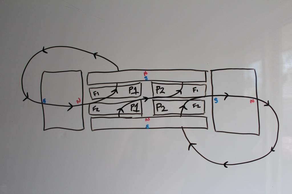
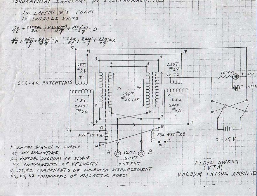
By superimposing an alternating magnetic field perpendicular to the static magnetic field of the barium ferrite magnets, then if the alternating field had sufficient strength, a coil parallel to the permanent magnets' field would be induced with an electromotive force. This technique matches the geometry of Floyd's devices, however there are a few problems. One, from my calculations using known details and ampere's law of the Space Quanta Modulator Mark 2, the magnetic modulation would be far too low to create a significant effect on any output winding. Also, in one of Sweet's later devices, the input winding is parallel to permanent magnet's field, not perpendicular and the output winding is perpendicular instead, so no modulation effect would be observed.


Speculation 2, Reluctance Oscillations in Permanent Magnets:

We know Floyd Sweet was modifying permanent magnets to get interesting results, however there is a key in all the methods that Floyd apparently used. Magnetic fields, high voltage, and heat, all of these things/techniques have one thing in common, they demagnetize permanent magnets. In Sweet's later devices, the magnets could have been severely demagnetized from an internal flux density of thousands of gauss, to only a few hundred gauss. This indicates the oscillation effect of the magnetic field did not require the oscillation of a huge amount of flux with a properly designed device. Further proof is indicated by the fact that in the Floyd Sweet Secrets video, when the device is switched on, there is no movement of the ferrous shim stocks on top of the device.

Furthermore, if the entire around 3,900 internal gauss field of the magnets were in oscillation at around 60 to 400 hertz, we should see enormous induced electromotive forces at the output, even with a small amount of turns on an output coil, but we do not. In fact in many of Sweet's later more powerful devices, had beefier input and output coils, along with attempting to push input currents into the input coils being up to 2 amperes. Clearly, Floyd Sweet was interested in getting the magnetic field of his input coils up in some circumstances, not just injecting microampere currents in his first working device, why would this be?

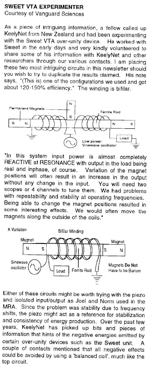
With this speculation and line of thought, I feel it may be possible Sweet was using controlled demagnetization, not to trigger some new magnetic effect necessary, but utilize the demagnetized domains in the magnet(s) as a magnetic core material. Along this thinking, Sweet could've used the input coil to control the saturation of these groups of "loose" domains, since under normal circumstances such domain groups created through controlled demagnetization would attempt to align themselves with the magnetic forces exerted by the other magnetized domains. By utilizing an oscillating magnetic field in the input coil, this would therefore modulate the magnetic reluctance of the permanent magnet itself, and cause the surrounding magnetic flux of the magnets to automatically redistribute itself under such influence. With sufficient oscillations and windings in an output coil, this could perhaps induce a sufficient electromotive force to do useful work.

This idea stems from similar principles involved in several claimed machines that can tap useful output utilizing permanent magnets. The concepts of magnetic amplifiers/saturable reactors and parametric transformers also have definite similarities to this concept. Like a magnetic amplifier, we see the amplification gain may be quite high. Magnetic amplifiers also utilize proper feedback techniques to have high gains, something we know Floyd Sweet was doing. In Sweet's SQM device, he utilized a signal diode we he says feeds a microampere current into the output coil, but there could be such an action the other way around. Also, inrush currents could've played a role in getting such reluctance oscillations to appear in his magnets.

Another piece of evidence, is that Floyd kept the name the same in his original devices, from the "Static Space Quanta Modulator Mark 1" to the "Static Space Quanta Modulator Mark 2". If Sweet knew how his device was going to work, why keep the name the same? If it was truly extracting some mysterious energy from the vacuum, why keep the name the same during the first successful tests?  It was only later when Floyd changed the name at Tom Bearden's suggestion to the "Vacuum Triode Amplifier", along the same time Sweet started to purposefully lie a deceive people in person and in some of his writings (past 1986). So what does that tell you? I think the reader can decide the answer to the previous question.


Conclusions and Strange Things:

There were some strange things claimed that Sweet's device could do, along with some unexplained things. Admittedly, Floyd's device is a mystery. Some of the strange things are:

  1. There's a story that Tom Bearden describes where he took one of the permanent magnets in "self oscillation", where a shim stock would shake on its own on top of the magnet without any other aid. Apparently, he locked the magnet in a safe, and the next day checked and saw the shim stock was still oscillating. It may be possible the Floyd was purposefully deceiving Bearden, perhaps part of the safe was magnetic and Floyd hid some oscillating solenoid. Or Floyd has a genuine effect here.
  2. The device apparently can create gravitational effects when properly configured. This was communicated to Tom Bearden in a phone call with Sweet. This may or may not be true.
  3. The device allegedly frosted Sweet when the device short circuited, and caused a while for Sweet to recover. 
  4. The device's output power is alleged vary during day and night.
  5. Floyd Sweet wrote in one of his paper's "Cosmic Rays, Natural Magnetic Fields, Coheret Quanta Energy and Aurora Borealis", he claimed to observe a magnetic modulation effect from an unknown source occurring in his crt television of all things. Perhaps this effect may be closer to the truth if something new, if other explanations of Sweet's device fall through.


There's many more things of course, too long to mention. I've been writing this post for a while now, so I'll put what I've written. Feedback will be appreciated.

  • Liked by
  • Chris
  • ISLab
DoofusNugget posted this 03 October 2021

kaos,


Thanks for the contribution to this thread. The image you just posted, I do in fact have a full copy of that document in image form of where it comes from, as I'm sure you do too? It is interesting to look at the progression of Floyd Sweet's work from the beginning in late 1985 to early/mid 1986. Floyd's early work in my mind, holds many answers to the operation of his concepts and device. 


kaos posted this 29 September 2021

DoofusNugget posted this 26 September 2021

On the Magnetic Oscillations in the SQM:


Hello, since I've already posted the work I've done so far in my previous post, I'll probably put some posts in this topic on my thoughts on the Space Quanta Modulator/Vacuum Triode Amplifier through the research I've done up to this point. Firstly, one interesting thought relating to such a device is realizing the main question: "If the pumped electrical current output from the device was from electromagnetic induction, what way did the magnetic fields in the device need to be oscillating?"

We know that an electric current can be forced through a conductive material utilizing relative motion of the conductors or the magnetic fields. We also know that this can apply to a magnetic field with a varying intensity in time, where the magnetic field strength is modulated in a given space. Take an elementary electric generator, with a single loop and an armature field. Let us rotate the coil on an axis such that there is a net current flow, to find the direction of the current in each part of the loop, for a known direction of rotation, we can apply the left hand rule.


Of course depending on your frame of reference, it doesn't have to be the conductor rotating in space, but the magnetic field of the armature can be rotating and likewise produce equivalent an effect. Therefore, with a single loop, magnetic flux is moving in one direction in one half of the loop, and magnetic flux is moving in an opposite direction for the other half of the loop, this allows current to flow through a closed electrical circuit with the attached loop forming part of our circuit. We also have transformer induction, where an expanding and contracting magnetic field around a conductive winding will drive current through the winding.

If we have an expanding magnetic field outward in the center of a winding, current will flow one way. If we have a contracting magnetic field in the center of the coil, current will flow in another direction. We flip the polarity of our magnetic field, the direction of induced current will reverse. Whether by "modulation of field strength" or "modulation through translation movement" of a magnetic field, the effect is the same, we can drive electrons to flow in a conductor.

Regarding such topics to the SQM, there was a very good point Chris had made in one of his videos. Here is the video:

Chris talks mainly about his continuing thoughts on "magnet conditioning" in there, however late into the video around 32:12, he remarks on his solution to the conundrum of how a net current flow could be induced. Although, I most definitely agree that such a conundrum is important to solve, I cannot agree with his solution, due to the fact Chris assumes the field is oscillating side to side, which I feel is probably not the case to how I've approached the problem. Rather I feel the evidence points to the magnetic field in at least the first working SQM, the field which induces current into the output coil but also input coil oscillates in a manner similar to the field in an electric generator, or if you'd rather like a metronome. 

If the field in the device oscillated in a manner like a metronome, then current could be induced not only the single output coil, but the input coil too (the lab notes from 1986 indicate this, since the input coil has a much high impedance under operation than can what be accounted for with the calculated impedance of the coil outside the field). We also know in some of Floyd Sweet's later devices, that he actually had the input/excitation coil parallel to the magnetic field of his permanent magnets, not perpendicular. In that kind of iteration, he had his output coil perpendicular to the magnetic field instead. 

I would like to point out in Chris's proposal in his video I linked above, would imply that there can be no current flow induced in the input coil by checking using left/right hand rules if the field was moving side-to-side. But we know this cannot be true due to the evidence presented, otherwise Floyd's input coils would've always had to be in the figure-8 shape (if the idea did work) as Chris suggested. The simple fact is that Sweet used at minimum, one input coil, one output coil. Sometimes he used multiple coils, or noninductive coil arrangements, caduceus coils, but the point is in the beginning of his first working device, only one input and output coil.

I'd also like to say, that I feel that there is probably no other way for Floyd's device to work if the magnets hadn't been modified in some way, whether it's by the processes presented publicly like "magnet conditioning", or some other confidential thing he didn't reveal much of (which he very likely did do). Considering this I think that if indeed the magnetic domains can be put under such oscillations, then in Sweet's magnets at least, I don't think all the magnetic domains were oscillating, but only a smaller number of them compared to relatively stationary ones. Otherwise, we would see such significant oscillations be present in shaking such ferromagnetic shim stocks we saw in the video "Floyd Sweet's Secrets". 

I'll probably make another post another time to continue this thought, but I recommend if people are interesting in the working of the SQM, then consider how the magnetic fields needed to oscillate for current to be pumped in not only the output coil but the input coil too. I'd recommend also looking at different kinds of magnetic machinery to understand the different possible magnetic configurations, which had helped me understand how the SQM's magnetic field of the device which controls the output may be oscillating. 

What is an Amplidyne? - Circuit Globe

AMPLIDYNE PDF

DoofusNugget posted this 24 September 2021


Hello, below is the writing from the document I was referring to in this thread. It's copied directly from the Microsoft word document (I assume that'll be okay due to Chris's above statements), and I pasted in the images by hand here, so anyone here can see what notes I've been taking. As I've said, it's incomplete, I have lots more information to put on this document, mainly for myself and also others who happen to view this, so it may become a very large document in the future since it's already about 20 pages currently.

___________________________________________________________________________________________


Space Quanta Modulator Speculation and Notes


NOTE: There may be slight errors in this paper. Please check the facts for yourself and do your own research, and not let someone else do all the work for you!

NOTE: This is still in writing by the author as of now. It’s a rough draft basically.

NOTE: This document was last edited on, 9/23/2021.


Space-Flux-Coupled Alternator (1985-1986):

Agreement Between Mark Goldes and Floyd Sweet, on December 29th of 1985:

John Bedini Handling Floyd Sweet’s Documents:

The Space-Flux Coupled Alternator:

Static SQM Mark 1 (1986):

Plans for the Static Space Quanta Modulator Mark 1, by Ashley Gray, on March 22nd of 1986:

Similarity Between Static Space Quanta Modulator Mark 1 and Heinrich Kunel’s 1980 Patent:

Known Construction and Parts:

  • Two neodymium permanent magnets of 7/8 inch by 7/8 inch in area. These permanent magnets are arranged onto E-core-like steel magnetic structure. If the magnetic circuit is to flow through unimpeded in a closed path, the magnets need to be in attraction.
  • Two modulation coils are arranged parallel to the flux path of the two neodymium magnets. These two coils are said to modulate the space quanta already in a coherent state due to the permanent magnets.
  • One output coil extracts the useful electrical output from the magnetic oscillations in this device.
  • The device was driven a by 1-2 kilohertz purpose-built sinewave oscillator.

Notes:

  • The device apparently did not produce the expected results. Ashley Gray claimed that Floyd Sweet mentioned in the lab notes that, the flux was paralyzed due to the high field strength of the neodymium magnets and the closed magnetic path. However, there are no parts of the lab notes remnants which mention this, meaning that this part of the lab notes that mentions this is lost.
  • The device is very familiar to a patent iteration by Heinrich Kunel, from 1980-1982. Figure 7 of Kunel’s patent has two input coils for controlling the permanent magnet flux, one output winding, along with the fact the input coils could be driven by alternating currents. A low-reluctance magnetic path (air gaps) is also present in Kunel’s patent and Sweet’s device in the same areas. This gives rise to speculation the Floyd Sweet intended this device to be operated in a manner similar to Heinrich Kunel’s generator from six years prior.
  • Floyd Sweet’s earlier work implies he was concentrated on devices that used “magnetic switching” principles, and on superimposing a motional magnetic field on a static magnetic field (from permanent magnets or solenoids) to produce a net motional magnetic field. For example, in a one of his paper’s, “The Space Quanta Modulated Mark 1 Static Alternator”, Floyd Sweet states, “Laboratory experiments dealing with magnetic fields support the concept that magnetic flux may be modulated by low level oscillatory means. However there is no lateral movement of flux. Rather, what happens is that the individual packets of quanta are polarized by the initiating and sustaining coherent force the field of the primary magnets or in special cases, electromagnets.”
  •  


SQM Mark 2 (1986):

Strange Magnetic Oscillation Phenomena in CRT Television Discovered in early 1986:

Space Quanta Modulator Mark 2 in the Lab:


Ashley Gray’s Diagram of the Space Quanta Modulator Mark 2:

Floyd Sweet Powering Four Car Bulbs (6 Watt Load):

Interior Shots between the Magnets and Coils:

120 Turn Excitation Coil (E-Coil 1):

  • Radius = 0.75 inches/0.01905 meters
  • Turns = 120
  • Length = 2.5 inches/0.0635 meters
  • Wire Gauge = #20
  • Inductance = 324.86 uH
  • Approximated Resistance = 0.529 ohms
  • Inductive Reactance (400 Hz) = 0.816 ohms
  • Impedance (400 Hz) = 0.972 ohms
  • Internal B-Field (3.1 uA) = 7.362 nanotesla/73.617 microgauss

250 Turn Excitation Coil (E-Coil 2):

  • Radius = 0.75 inches/0.01905 meters
  • Turns = 250
  • Length = 2.5 inches/0.0635 meters
  • Wire Gauge = #18
  • Inductance = 1.41 mH
  • Approximated Resistance = 0.628 ohms
  • Inductive Reactance (400 Hz) = 3.544 ohms
  • Impedance (400 Hz) = 3.599 ohms
  • Internal B-Field (143 uA) = 707.477 nanotesla/7.075 milligauss

12 Turn Power Coil (P-Coil 1):

  • Radius = 0.75 inches/0.01905 meters
  • Turns = 12
  • Length = 2.5 inches/0.0635 meters
  • Wire Gauge = #12
  • Inductance = 3.249 uH
  • Approximated Resistance = 7.47 milliohms
  • Inductive Reactance (400 Hz) = 8.166 milliohms
  • Impedance (400 Hz) = 11.067 milliohms
  • Internal B-Field (500 mA) = 118.73 microtesla/1.187 gauss
  • Internal B-Field (1.84 A) = 436.95 microtesla/4.37 gauss

24 Turn Power Coil (P-Coil 2):

  • Radius = Unknown
  • Turns = 24
  • Length = 2.5 inches/0.0635 meters
  • Wire Gauge = #18
  • Inductance = Unknown

Loads:

  • 26-watt bulbs.
  • 1.5-watt auto lamp bulbs, rated at 12 volts, each bulb has a resistance of about 96 ohms.
  • 24-volt or 28-volt pancake motor, rated at 1/8 horsepower. This motor should be powered by direct current.

Known Construction and Parts:

  • An anodized aluminum box/tube with its dimensions being: 6 inches long, 4 inches wide, and 2.5 inches tall. The thickness of the walls of the aluminum box is between 1/16 to 1/8 inches, or between 0.0625 to 0.125 inches.
  • Two barium ferrite permanent magnets with dimensions of: 6 inches long, 4 inches wide, and 1 inch thick. These magnets are placed on top of the aluminum box in attraction mode. Note that Floyd Sweet’s later work implies that the magnets had to be “specially conditioned”.
  • One excitation coil which is oriented orthogonally relative to the magnetic field of the barium ferrite magnets The excitation coil has between 120-250 turns around a small tube which slides inside the aluminum box.
  • One power coil which is mounted parallel to the magnetic field of the magnets. This coil apparently has only 12-24 turns around a tube which also slides inside the aluminum tube.
  • A signal diode is connected in parallel with the excitation coil, this diode connects to the power coil. This is supposed to send a small microampere current into the power coil.
  • A signal generator provides a sine or square wave to the excitation coil, this apparently drives the magnetic field into motion under the proper conditions.
  • A full bridge rectifier using four stud diodes was used to power direct current loads from the output coil.

Separate Historical Tests:

  • 5 V and 3.1 uA on E-Coil 1, output on P-Coil 1 is 10.41 V and 1.84 A. Frequency input to E-Coil 1 is approximately 400 Hz. E-Coil 1 impedance is about 2.419 MΩ.
  • Output on P-Coil 1 is 12 V and 500 mA. Load is four 12-volt auto lamp bulbs, 6 watts output into bulbs. Output frequency is between 60 to 400 Hz.
  • E-Coil 2 input is 7.2 V and 143 uA, output on P-Coil 2 is 24.2 V at 4.6 A. The frequency is 388 Hz. Load is four 26-watt bulbs. Impedance of E-Coil 2 is about 50.35 KΩ.
  • Input on E-Coil 2 is 7.2 V and 146.7 uA, output on P-Coil 2 is 24 V at 4.63 A. Frequency is at 402 Hz. The load is four 26-watt bulbs, a pancake motor with full bridge rectifier was later added as another load (ratio of input to output with a pancake motor and bulbs is about 200,000). Impedance of E-Coil 2 is about 49.08 KΩ.

Notes:

  • Floyd Sweet added a signal diode to connect the power coil in parallel with the input circuit, which apparently sends a small microampere current into the power coil. There is a claimed “Halved A-Vector Complementation” occurring between the coils and magnet with this diode. The unit with the attached diode is called a “Vector Oscillator”.
  • Output voltage is claimed to increase with an increase in: power coil turns, frequency (it’s claimed the voltage at times goes down with increase in frequency at times), and power coil area.
  • The quality of the input signal is apparently important, “pure sine wave”, and there should best be no harmonic distortions.
  • The input current appears to increase with an increase in load, implying there is some form of coupling between power coils, excitation coils, and the oscillating magnetic field between the two barium ferrite magnets.
  • When this device is operating, the impedance of the excitation coils is millions of times greater than what can be accounted for when the impedance is measured at operating frequency outside of the device. Darrell Roberts (one of the writers of the lab notes), admits this and has no explanation for this discrepancy. The lab notes imply that the increase impedance is speculated to be due to inductive reactance, which decreased as the load increased.
  • The two 6” by 4” by 1” barium ferrite magnets used in the device were mentioned in the lab notes as having at least 500-plus gauss field between power and excitation coils, which is close to surface field calculations. Calculations have shown magnets of these dimensions and assuming a B-field of 3,900 gauss should have a surface field value of about 668 gauss, this value of the field appears less than an inch away from the magnet while at the central axis of the magnetic field.
  • This device could be driven by: a Wavetek 130 Function Generator, a purpose-built sine wave oscillator, a HP 211A Square Wave Generator, and the HP 201 C Oscillator. In other words, the device could be driven by both sine wave and square wave sources.
  • The lab notes make no mention of a core material in the coils ever being present, picture evidence also supports this conclusion.
  • The powered bulbs vibrate when put close to the magnets, implying the magnetic field is varying around the magnets, even if slightly. A varying magnetic field would exert Lorentz forces on the electrical connections of the bulbs (the filament or other wires), accounting for such vibrations observed. However, such vibrations could be contributed by the alternating currents in the bulbs too.
  • The lab notes say the pancake motor is rated 28 volts, but another source says the motor is actually 24 volts (Floyd Sweet’s Secrets Video from 1987). Though it may be possible Floyd Sweet had multiple pancake motors at the same horsepower that ran it different voltage inputs. More research will have to be done to determine which pancake motor was used.


VTA (1987-1988):

The Vacuum Triode Amplifier Powering Five 100-Watt Lightbulbs:

Vacuum Triode Amplifier Design Variation from John Bedini:

Loads:

  • 100-watt light bulbs rated at 120 volts. These bulbs should have a resistance of around 144.058 ohms.
  • A 120-volt AC fan motors. It appears the motor consumes about 100 watts at 120 volts from calculations, however the author feels uncertain about this number.
  • 24-volt pancake motor, rated at 1/8 horsepower. This motor should be powered by direct current.
  • 1.5-watt auto lamp bulbs, rated at 12 volts, each bulb has a resistance of about 96 ohms.

Separate Historical Tests:

  • Input is 10 V at 31.2 uA, output is 112.5 V at 4.7 A. Tom Bearden reads off the wattmeter as about 500 W, but the more accurate value calculated from voltage and current is 528.75 W. The power factor is measured to be 1, while five 100-watt light bulbs and an AC fan motor are being powered.
  • The input is 10 V at 29.2 uA. The output has several items are being powered at once which include: the 120-volt AC fan motor, two 12-volt auto lamps connected in series from a stepdown transformer, a 24-volt pancake motor coming from a full bridge rectifier connected to the stepdown transformer in parallel, and four 100-watt light bulbs are being powered.
  • The input is 10 V at 7.9 uA, the output is 120 V at 1.25 A which makes 150 W, the wattmeter reads 145 watts however. The power factor is measured at 1. The 24-volt pancake motor, 120-volt AC fan motor, and the two 12-volt auto lamp bulbs are being powered. Four 100-watt light bulbs are later connected, and the input current increases to 25.1 uA while the output power is read on the wattmeter to be at around 480 W.

Notes:

  • When this device’s load increases, the input power increases by the same number of times. For example, when the load increased from 150 to 480 watts, the input power increased by the ratio of the 480/150 or about 3.2 times (the current on the input increased from 7.9 microamperes to 25.1 microamperes). This implies that this device’s output does affect the input, indicating some form of coupling between the power and excitation coils is occurring, increasing current on the power coils lowers the impedance of the excitation coils.
  • The values of the coils between the permanent magnets are unknown, including how many coils were used. However, in Floyd Sweet’s paper “Nothing is Something” mentions the use of bifilar coils in this device, however when Floyd talks about bifilar coils, he does not always mean the expected definition involving windings directly touching, but rather multiple separate coils which may or may not be closely spaced or even overlapping.
  • At around 25:50 in the Floyd Sweet’s Secrets video, the frequency counter on the device’s output briefly reads 62 Hz, contrary to just several seconds later Tom Bearden reads it off to be 60 Hz exactly. This further supports the fact the device can operate at multiple frequencies.
  • The ferromagnetic shim stocks placed on the device don’t appear to vibrate or oscillate when the device is turned on. If the magnetic field of the permanent magnets is oscillating, then it oscillates in such a way that there is no movement of the shim stocks.
  • It’s claimed in Floyd Sweet’s paper “Nothing is Something”, that the device’s current put out is too large for what the wires of the device should be able to handle. Tom Bearden further states the output is “negative energy”. However, it appears there is limited evidence on film or in general to vindicate this claim. No documented data/numbers exist to demonstrate there exists a definite temperature change effect, or whether there is a more conventional phenomena at play.
  • The shim stocks standing on the device in “Floyd Sweet’s Secrets”, a stand up well even from some height away from the barium ferrite magnets. This implies the magnetic field of the permanent magnets was in good condition, and strong.

Chris posted this 22 September 2021

Hi DN,

Please feel free to post text and images to this thread.

With the many thousands of Ransomeware attacks currently, we need to be extra cautious with files/attachments.

We get attacked all the time here, its a common thing, because of what we do. For this reason, I urge caution, and same goes for all anywhere, not just here. I hope it save readers the headache!

I will delete this post once read, to save your thread's space.

Best Wishes,

   Chris


P.S: No, you did not get my hopes up! If you do some research, you may see how far ahead we really are!

DoofusNugget posted this 22 September 2021

Hi Chris

No, I never met Floyd Sweet, he was way before my time, over a good 80 years, he was dead before I was even born. Sorry if I got your hopes up. The document for now contains: calculations/estimates based on known coil parameters, details and notes on the Floyd Sweet's Secrets video, known facts noted from the historical documents, some details on the Static Space Quanta Modulator Mark 1, that's mostly it up to now.


But as I said, it's a work in progress, you'll see some of the things I've mentioned in that document however if you get the chance to read it. I understand the precautions, if you need anything from me just let me know. Thanks.

Chris posted this 22 September 2021

Hi DN,

Did you have any direct dealings with Floyd Sweet back in the day?

For the moment, I have disabled your file. We will look at your file, when we get to know you a little better, please understand the precaution for the meantime.

Best Wishes,

   Chris

  • Liked by
  • Shadow_
  • cd_sharp
We're Light Years Ahead!
Members Online:

No one online at the moment


What is a Scalar:

In physics, scalars are physical quantities that are unaffected by changes to a vector space basis. Scalars are often accompanied by units of measurement, as in "10 cm". Examples of scalar quantities are mass, distance, charge, volume, time, speed, and the magnitude of physical vectors in general.

You need to forget the Non-Sense that some spout with out knowing the actual Definition of the word Scalar! Some people talk absolute Bull Sh*t!

The pressure P in the formula P = pgh, pgh is a scalar that tells you the amount of this squashing force per unit area in a fluid.

A Scalar, having both direction and magnitude, can be anything! The Magnetic Field, a Charge moving, yet some Numb Nuts think it means Magic Science!

Message from God:

Hello my children. This is Yahweh, the one true Lord. You have found creation's secret. Now share it peacefully with the world.

Ref: Message from God written inside the Human Genome

God be in my head, and in my thinking.

God be in my eyes, and in my looking.

God be in my mouth, and in my speaking.

Oh, God be in my heart, and in my understanding.

Your Support:

More than anything else, your contributions to this forum are most important! We are trying to actively get all visitors involved, but we do only have a few main contributors, which are very much appreciated! If you would like to see more pages with more detailed experiments and answers, perhaps a contribution of another type maybe possible:

PayPal De-Platformed me!

They REFUSE to tell me why!

We now use Wise!

Donate
Use E-Mail: Chris at aboveunity.com

The content I am sharing is not only unique, but is changing the world as we know it! Please Support Us!

Thank You So Much!

Weeks High Earners:
The great Nikola Tesla:

Ere many generations pass, our machinery will be driven by a power obtainable at any point of the universe. This idea is not novel. Men have been led to it long ago by instinct or reason. It has been expressed in many ways, and in many places, in the history of old and new. We find it in the delightful myth of Antheus, who drives power from the earth; we find it among the subtle speculations of one of your splendid mathematicians, and in many hints and statements of thinkers of the present time. Throughout space there is energy. Is this energy static or kinetic? If static, our hopes are in vain; if kinetic - and this we know it is for certain - then it is a mere question of time when men will succeed in attaching their machinery to the very wheelwork of nature.

Experiments With Alternate Currents Of High Potential And High Frequency (February 1892).

Close