MIT - Graham Gunderson

  • Topic Is Sticky
  • 4.2K Views
  • Last Post 02 November 2020
Chris posted this 07 July 2017

Perhaps the best Above Unity demonstration ever done, Graham Gunderson, a person I have known for a few decades now, has, for sometime now, had several Working Devices and has demonstrated some.

The MIT was shown to produce a COP > 4


With 8 Watts output and only 2 Watts input, measured, Accurately, on both Tektronix Oscilloscope and also Clarke-Hess Power Analysers - Very Expensive, world class Test Equipment!

Graham has also demonstrated other devices, similar:


This device was also shown at one of the Conferences, and measured to be Above Unity!

Graham is a first class engineer, he has spent much of his working career measuring devices, Metrology is his profession!

   Chris

Order By: Standard | Newest | Votes
Chris posted this 02 November 2020

Thanks CD,

I have to have a little giggle, I have seen most all of what Graham is presenting before, and all readers of this Forum has also! Even the Argand Diagram, the Source of Energy, my recent video, same content, it is good to see others out there working on sensible logical information.

I like Graham, he and I have had some communications in the past, he puts the other forums to shame also! He shows how backward they work!

Best wishes,

   Chris

Chris posted this 09 October 2019

My Friends,

Graham Gunderson has released a few new videos:


Good Job Graham, Thumbs up from me! Go and visit Grahams Channel, and give him a Thumbs up, support his effort!

I bet our little sweet hearts that Trolled Graham Gunderson are not only out of a Job, but very sad that they are not a part of the Future of Humanity!

   Chris

Chris posted this 16 September 2019

My Friends,

Jagau is spot on!

4 micro seconds is fast and it could be 250 khz frequency.
As it should not touch the red zone of the cycle
so everything is a question of timing I think.


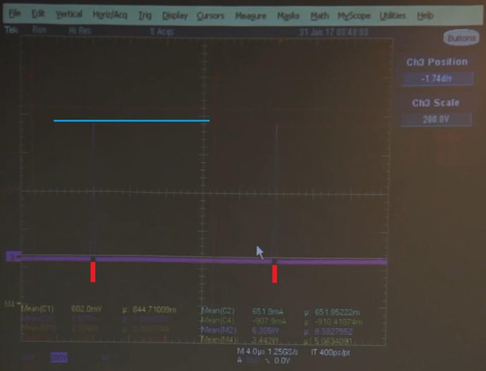
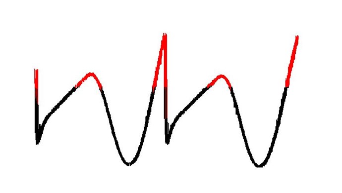
What does this sharp drop and reconnection do? It does this:


Graham Gunderson's Left Side Partnered Output Coil was connected permanently to the Load, Capacitors and Globe:

For the entire time, between the Red markers! The Red markers indicate Off Time! Thus the Voltage Spike! Almost 700 volts. The Bottom Purple Line between the Red markers, is 9 Volts on the Capacitors, Conduction, Connected to the Output!


The Time Rate of Change of the Magnetic Field Creates Voltage!

Grahams was 700 Volts!

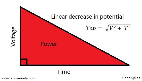
Then we wait, we Conduct and then do this:


Which is exactly the same as doing this:


Most of you are spot on, some here only need to get the voltage up!

Notice Fighter's spike here! L + R Output Coil Spike. If the input is 10 volts, then you need to get the Output up to 20 Volts around about.

I hope this helps!

   Chris

Jagau posted this 16 September 2019


4 micro seconds is fast and it could be 250 khz frequency.
As it should not touch the red zone of the cycle

so everything is a question of timing I think.

Jagau

Chris posted this 15 September 2019

Ok, My Friends,

What are we missing? What's not on this thread?

Ok, so, Scientifically, what do we know.

1: Input Winding appears to be 10, 12, 10, 12, 10, 12, possibly only 6 layers, of Litz Wire, about AWG 2 (6.54304 mm) @ approx 0.512664 Ohms per KM.

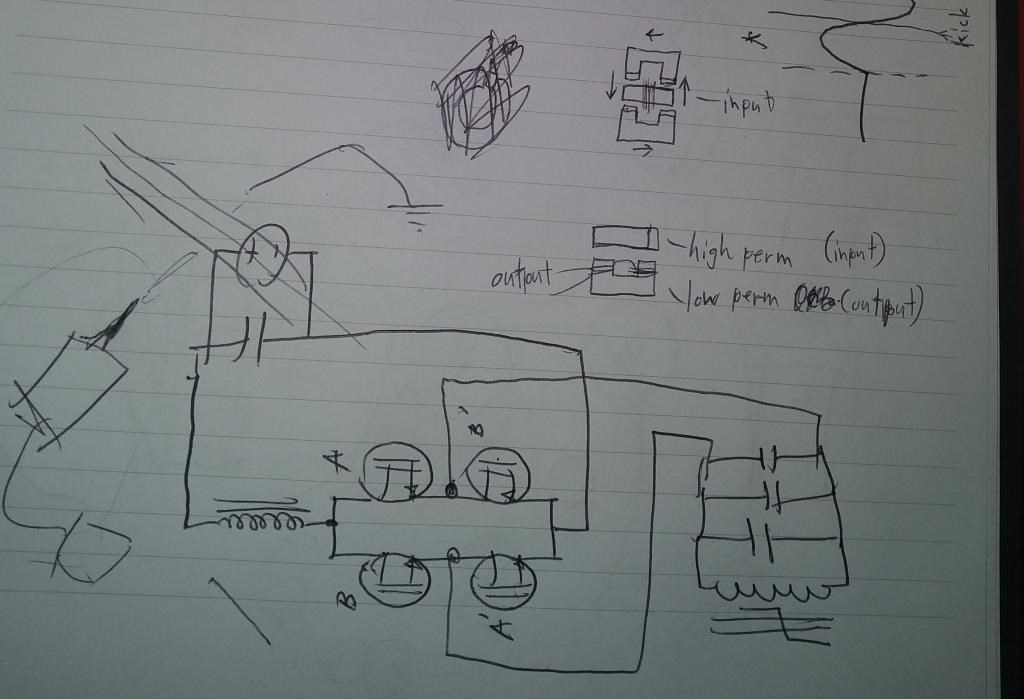
2: Output Coils consist of 4 Strands of Litz wire, each wound side by side, in a step winding configuration, Almost Bank Winding. Each set of winding's is divided into two parts. Each set of windings appear to be wound CW/CCW relative to the Core.

3: Output is DC, Rectified, via a circuit arrangement of possible 30 odd components.

4: Pulsed DC is the Input. As Reiyuki points out, about 33% 33% 33%

5: Permanent Magnets are arranged on the Device, thought to Bias, or partially saturate at least one half of the U Cores used.

6: U Cores are a Ferrite Material, apparently each has a different value of Permeability. No specifics that I know about have been shared as yet. (The below product guide, has an AL range from: 2300 to: 8700 (nH measured in combination with another ungapped core half))

7: U Core appears to be approximately square, a product selection guide can be found here: Ferroxcube, the largest U Core in this document is in the Picture below: (Which is about right, I have some magnets the same here (25 x 40 x 10) and they would fit about the same on the Core)


All in all, what’s the Key concept here? Time Rate of Change of the Magnetic Flux, and the second key point is there are Two Output Coils, arranged specifically in separate space on the second half of the U Core. Electricity is the end result of Electromagnetic Induction, time rate of change, where in the Input Coil is the Prime Mover, which is mostly or completely unaffected by the Drawing of Current on the Output.


Ref: Graham Gunderson's Energy conference presentation


Another:


Thanks to Reiyuki's awesome documentation efforts, and for others out there interested, I have done some ID'ing on the IC's

I believe all the Opto's are the same, as the surrounding circuitry is the same. Some appears to be redundant, I may be wrong however.

Red Circles: NEC PS 2505
Green Circle: IXDD614PI
Blue Circle: IL710
Yellow Circle: 74AC14PCX

Please check for yourself, I am not 100% sure on all of them, if is very close if I have not got it spot on.

The Output Caps:
3 x Felsic Aluminum Electrolytic Screw Capacitor 2200µF 350Vcc
2 x Kemet Arcotronics AV MKP C4BTHBX5100Z_L_ Style A 10uf 600V

This is a lot of ciruitry for Synchronous Rectification, Texas Instrunemts has a good doc on this, that is, if this is what Graham is doing?


Ref: Graham Gunderson's Energy conference presentation


So, basic parts list is now built. We have Bias Magnets also.

We have a Gapped Input Core, compared to the Closer Coupled Output Coils on the same core! Partnered Output Coils! Partnered Output Coils are on the same Core!

So what, if anything, do we have here that is remarkable? We have nothing remarkable!

Whats going on? Its the timed interactions of the Partnered Output Coils!


Ask yourself: What is the timed interactions of the Partnered Output Coils? Why, what does this timing do? What are the fundamental rules of Electromagnetic Induction?

A lot of this has been covered in the thread: Important: Delayed Conduction in Bucking Coils

Datasheets below:

   Chris

Attached Files

Chris posted this 18 January 2019

My Friends,

There is no Magic to this, although it was implied in the pdf:

If so it is an over-complicated method of producing the flux changes needed, relying as it does on specially conditioned primary and secondary currents.


Now where have we heard this before? I have been showing you this for more than 7 Years:


Electromagnetic Induction can account for every aspect of this Technology, not a single bit of Magic anywhere that a standard off the shelf Chinese "Generator" does not already incorporate either knowingly or un-knowingly to minds in Science. Ferro-Resonance is a term used to entertain an unstable System, which is easy to employ, an Asymmetrical System is inherently unstable.

Currents in the Coils are the only required Resonance as such, where the Currents must be equal and opposite at time t.

This is Magnetic Resonance.

Any and all Coils with a Voltage Potential on the Terminals, have the Potential for Current to Flow!

All you need to know is:

  1. Voltage is the result of the Change of Magnetic Fields.
  2. Current is the result of Opposing Magnetic Fields.


We learned this in The Mr Preva Experiment! Its so extremely simple, so please don't let anyone confuse you!

   Chris

alohalaoha posted this 18 January 2019

Any partnered bucking configuration has direct influence on Etheric flow/s and vice versa. Only remain for us - to find out how ?

Don't throw Tesla's words over the own shoulders - "There is NO ENERGY in the MATTER - only in Ether !!!!".

If somebody had knew most about Ether, for sure he is on the 1ST.PLACE !!

Read old Tesla's interviews to correct own outlook at physic !!

Reg.

Aloha

Jagau posted this 18 January 2019

Another very important point that I noticed in this video

is that the coils are far from each other but in very close magnetical relation,

in my personal experiments I noticed an increase of the gain

when we place our coils the same way

Jagau

Jagau posted this 18 January 2019

This may be the reason for the poor viewing of his video,

many have not bitten.

AN important point in this video forgotten by all is magnetic ferroresonance.

Jagau


Chris posted this 18 January 2019

Hey Jagau,

Thanks, I have seen that. My personal opinion is that this is wrong, it also uses way to many 'could' words.

Graham Gunderson used to work with Cyril Smith at Chava Energy and before that at Magnetic Power Inc (MPI), for Mark Goldes. I personally think these two gentlemen should have known each other better and collaborated on this topic well before releasing this sort of thing into the public domain!

I am somewhat skeptical, I do believe forces are at work to throw people off, to lead people down rabbit holes, I have seen it before with the "Magnet Conditioning" of Floyd Sweet, and also other places!

Why do some people lie, cheat, steal, miss-lead, do wrong by others all the time? I don't know, but I urge all here, stay on target, don't let yourselves get sucked into miss-leading gumf!

There is an extremely simple, realistic explanation to what I am sharing with you and it breaks not a single Law of Thermodynamics or any other fundamental Law of Science as we currently understand it today. The only requirement is one must be slightly open to interpretation of the ways the Law's can be applied.

Note: Floyd Sweet was sponsored by Mark Goldes before Tom Bearden was on the scene, then as The Aesop Institute.

   Chris

Jagau posted this 18 January 2019

I found a document that might interest you Chris.
About Gunderson and the video experience you recommended to me.
They arrive at the conclusion that .....
Re: look at the performance of ferrite PE22

Jagau

Attached Files

  • Liked by
  • ISLab
  • Augenblick
Chris posted this 15 February 2018

My last post, creating a peak magnetic Field with no Interactions during this phase, has been pointed out in the: 

Parametric Excitations of Electric Oscillations


In this thread, I point out, there is a Transformation, from Electric Field to Magnetic Field.


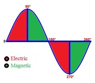
You don't want to touch the Red Phase, thus it is Red. You want the Green Phase, here, all the Electric Field stored on the Battery, has been transformed into the Magnetic Field. We have all the Energy stored in the Magnetic Field and none in the Electric Field.

The Magnetic Field Creation Phase is critical, it must not be interrupted!

   Chris


Chris posted this 15 February 2018

I asked the question here:

Question

 Why was a Mosfet used in the MIT? What was the purpose?


Answer:

To stop the Electromagnetic Induction process from the Input Coil to Output on L2 during the Magnetic Field Creation Phase.


In other words, when the Magnetic Field is Created by L1 (Primary Coil), E.G; We have peak Field, Maximum Current and the Field is now moving toward Zero, the Mosfet turns On. L2 and L3 then do Work to Separate Charges, Current, and the Output for this given set of Parameters is in excess of the Input: COP > 4.

   Chris

Chris posted this 08 February 2018


Again: Geometry!

Grahams device, the MIT, Three Coils, One Input Coil, Two Output Coils.


Graham was straight up with you, 100% He drew the Output Coils for the crowd:


 So what does Graham do?

  • Inject Magnetic Field into the Core - Very little Electromagnetic Induction from Input to Output!
  • At peak Magnetic Field - Current - Output Coils are Switched on.

This is a timed response, the MIT is Generating Energy because of Electromagnetic Inducion, Asymmetrically, Input and Output are Disconnected.

   Chris


  • Liked by
  • ISLab
  • Augenblick
Chris posted this 29 November 2017


I would like to gently remind all here of the importance of what we are learning:


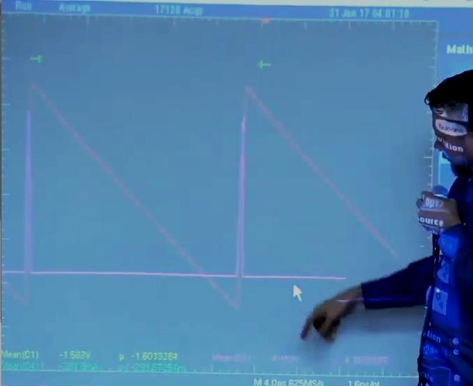
By looking at the Current Wave Forms, one can see what's going on in the Core, Hysteresis, this is Electromagnetic Induction.

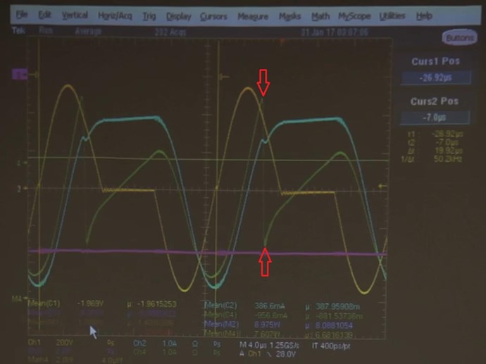
Below, in light Green, we see the one of the Output Current Wave Forms:

The wave itself looks like this: 

 You can see, the Current changes Polarity, Very Fast, almost at Mid Cycle: (Green Arrow)

A lot os questions can be asked, most all have very simple answers! 

From the Peak of the Current Wave form, where it Very quickly changes polarity, to the actual change in polarity, is about 4 Micro Seconds. Very fast!

Because we know that Graham Gunderson uses Partnered Output Coils, and we know that the Coil being measured, Flips polarity, very quickly close to the Peak Current, we know at this Point that the Magnetic Fields Oppose, as the Currents must also Oppose at this point, between the two Output Coils.

Graham is holding the Coil Polarity in one Direction, until close to Top Dead Centre of the Current Wave Form, then Dropping the Polarity with a Switch, a Mosfet. This circuit we know already:

It turns out, this is a similar method of Operation as Bradleys RT. This is a type of Resonance, where we are bringing about, by means of a Timed Response, Maximum Electromagnetic Induction for Minimum Input. The Input is doing work on the Core, and getting Electrons Flowing in the Coils, but then the Polarity Flips and this is when the Magic Happens.

Note, this is a 1/4 Wavelength, you may see some Correlation to this Image now:


You can read more here: Electromagnetic Waves if you want more information.

   Chris

Graham has two output Currents, exactly the same as in The Mr Preva Experiment, that are being Amplified, by opposing Magnetic Fields, that are switched in at TDC.

I also showed the same techniques here: Some Coils Buck and some Coils DONT

Time Rate of Change is Electromagnetic Induction, so faster the better!

Study the scope shot, what I am saying is right there in front of you, one just needs to understand it! Its really simple once understood, however still a little tricky to replicate, some work is required!

   Chris:

Zanzal posted this 31 July 2017

I came across this device patent from Graham Gunderson. Not sure if it describes a working device but it is definitely interesting.

Attached Files

Chris posted this 25 July 2017

Hi Cd_Sharp - I do not understand your question, can you please explain further.

Well, I was confusing the time constant of a coil with the Q-factor.

I'm thinking we can achieve what Graham has achieved by properly balancing the primary coil and POC coils. What this means I am not sure. I'm still "fiddling" to find this balance.

Hi Cd_Sharp - That's it, it is a balance, there is a little fiddling to this! Its not always easy!

The mind plays tricks sometimes, and it is not easy, but I would pick the best and most well documented and stick to the one project. I have found that Determination is key, self-discipline and a lot of cross-referencing with other data is the best way to move forward.

I had a hard time sorting through the Lies in Bradleys Rotary Transformer, but in the end it was only common-sense and something we had already studied that gave me the info I needed to make progress.

Its frustrating, but I always think of Nikola Tesla and the show of discipline he showed for many years!

   Chris


Wistiti posted this 25 July 2017

I have little spare time but I want to help.With the hope that we will find a working principle,you can count me in.


Nice post Vasile!

Im also like you, "I have little spare time "

But you guys can also count me in!

I think we have the base theories on the working principe; we now need some team builders working on the simplest device we can, so even the new one can easily participate.


Sincerlly!


Chris posted this 24 July 2017

Graham does all I describe above, by DC Switching

This is a hard method. Synchronous rectification is not something I would try soon because I do not have the skills or tools for it. I think there should be at least one easy method to do the same thing.

Two Output Coils MUST Oppose, normally this is a 1/4 Wave Opposition, or is subject to the Current Flow with Wave Propagation Principles similar to that of Radio Wave Theory

Since Q factor is a fifth of the time it takes for a coil to fill up, is this achievable by using a Q factors match between primary and output coils? Is this an easy method to do what Graham did?

Hi Cd_Sharp - I do not understand your question, can you please explain further.

Q-Factor ( ω ) = ω × Maximum Energy Stored / Power Loss

or

Q-Factor ( ω ) = 2πfr × Energy Stored / Energy Loss

So, in Grahams System, the MIT, we have a Gain in Total Energy, of 6 Watts, which would mean we would need to divide by a negative Number, there is no loss, there is a gain.

This is a Underdamped System, with No Damping, there can be Energy Gains.

Please don't misunderstand me, we still have Losses in the System, but the Losses are over come by the Gains.

Bradley's RT Does exactly the same thing as Graham does! Yes its not exactly easy, but with some fiddling it does work!

   Chris


Chris posted this 23 July 2017

@Aloha - Apologies, I was generalising, there was no direction to my comments about endless debate. Graham is not an active Forum Participant was more so what I meant. At least not that I know of.


If not already done so, the in depth study of the Electrical "Generator" should be our Primary Goal to take the next step forward. Learn how Electricity is "Generated".

  • A Source Magnetic Field with Density B in Gauss (CGS Units) or Tesla (MKS Units).
  • A Change in this Magnetic Field in proximity to an Insulated Wire.
  • The Change in Magnetic Field from the Source Magnetic Field, to the Invoked Magnetic Field, Oppose.
  • Each Magnetic Field and therefore direction of Current are subject to Newtons Laws of Motion: For every Action there is an Equal and Opposite Reaction and for every Reaction there is an Equal and Opposite Counter-Reaction.
  • Two Output Coils MUST Oppose, normally this is a 1/4 Wave Opposition, or is subject to the Current Flow with Wave Propagation Principles similar to that of Radio Wave Theory.

I am still learning, Graham said he does not know how it works, but has some ideas... So we all are in the same boat. We need to work together to nut out the problems.

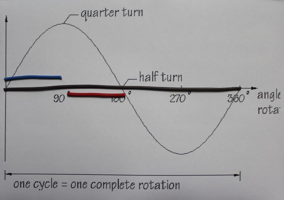
There is a huge amount of meaning to the Images I posted!

What is this meaning?

Well lets see:


    • The long Brown wire is the Primary Coil, with a Frequency: x indicated by a single Wavelength.


    • A Partnered Output Coil is added, the Blue Wire, this is 1/4 of the Wave Length of the Primary Coil in this Case. So current will be entirely at one end of the Wire according to Wave Theory.


    • The second Partnered Output Coil is added, the Red Wire, this is also 1/4 of the Wave Length of the Primary Coil in this Case. So current will be entirely at one end of the Wire according to Wave Theory.


    • Each of the Partnered Output Coils are Wound Opposite, one Clock Wise, one Counter Clock Wise, so that means the Current will be on the opposite ends of the wire at any point at the 1/4 Wave Length.


  • This is the reason that the Fields oppose!


Without the Fields Opposing, there can be no Gain in Electrical Energy! We have seen this so many times now, All the major Devices All use these EXACT Same principles! Clemente Figurea, Kapanadze, Lester Hendershot, Floyd Sweet Akula, Ruslan, Steven Mark, Don Smith, All of them... And where you cant see it and have not been told so, then it is likely the secret of the Inventor.

Most of you, that have followed the MrPreva Experiment, will see why this is such an Important Experiment to do and understand! Its so close that its not funny!

We know 99.9% of how this works, we just need to 0.1% Fiddling to make the rest work!

   Chris


P.S: Graham does all I describe above, by DC Switching.


alohalaoha posted this 23 July 2017

Hi Chris

It is not about entering endless debate pont with Gunderson or anybody. Of course i also hate that.

I am talking about very tiny processes which have invisible presence and interact at very fine levels or matter organised by MATRI-X. This is a CARBON WORLD, but before 7500 year IT HAD BEEN A SILICIC WORLD. MUCH MUCH PERFECT than this. And proof for this are at every step. The real human beings just need learn to look and see without MATRI-X filters Chris.YES. MATRI-X is REAL Chris. it is not mirage or someone final fantasy.


What i want to tell Gunderson,Chris is this

He has deal with MATRI-X. Tranformer in presence of at least one short-circuited winding remember the previous state. And the core is demagnetized, and there is no more current in the windings, and you can wait for at least a week or more. But the transformer anisotropy is preserved, and only for the first pulse,Chris.If the voltage is applied in the same direction like preserved state remembered, and there is some way to go out, for example, there is a conderser, then it will be charged immediately. And if the voltage is opposite, then it first falls on the inductor, what is interesting moreover longer than usual voltage drop and the same capacitor is not charged fully only weak charged, but remembered process state is turned off.

What is this "artifact" Chris, and where does he live?

Chris you understand that it is the memory of inductive resistance, but only for the first pulse. The friend Phantom called this "pimple".

But this effect is so bright and clear if there is proper pulse potential, which becomes a trigger.

Aloha

  • Liked by
  • Chris
  • Augenblick
Chris posted this 21 July 2017

Agreed Aloha - The Matrix is a Mind Set, We all need to Choose: Blue Pill or Red Pill


There is a lot of problems! Some are very much more advanced than others, mostly through Choice, freedom of Will. We choose to try harder, think smarter, to progress in our life skills. We all should, but some choose not to.

 I have spoken with Graham once or twice lately, and his mind is in other places at the moment. I detected that he is not wanting to enter endless debate with people that know no better and choose not to.

There are area's of improvement, where small changes can make big differences to the performance! But this is all for another day! Lets get those that choose to progress, progressing! Start the ball rolling...

Graham Gunderson has done more than his fair share, he has provided several demonstrations with very much more than over whelming evidence of Working Devices - His work supports my work 100% it is the same work! Nearly exactly the same:

This is mine, more than 6 years ago:


This is Grahams a years ago:


The over all difference, very little. His Device does work slightly different. Both reach the end goal but slightly different ways.

   Chris

alohalaoha posted this 21 July 2017

Hi Chris

NOT ALL SO EASY AT FIRST GLANCE. AS YOU THINK.!!!!

Problem of mutual interaction of Vector magnetic potentials A of both partnered-bucking type Hooper coils is begining of story for free energy extraction from highly organized forms of plasma from higher octaves of reality.

Well CHRIS, there is one very big problem with every single transformer whatever how he was wounded and connected. Problem is that there really exist - ENERGO-INFORMATION COPY - of every single transfor, known as MATRI-X'S FANTOM of transformer. He has fine ENERGO-INFORMATION structure at sub femto levels.


THE FANTOM

HE IS A MAIN MATRI-X's BLOCK for free energy extraction from A potentials as pure energy sources.

Chris, bring G.Gunderson here to show him how to unblock his device and how to shield MATRI-X's FANTOM in his transformer.

NOT ONLY TRANSFORMERS HAVE OWN FANTOMS - CHRIS. THE PEOPLE ALSO HAVE.... YES .... NIGHTMARE.

SHORTLY WE ARE IN MATRI-X CHRIS AND WE ARE TRAPPED. BUT EXIT REALLY EXIST AND NEVER CLOSED FOR THOSE WHO WANT TO TRY OWN WAY OUT.


THE TRIPLEX reality

1. BODY - THE HARDWARE "unwilling gift" from MATRI-X

2. SOUL - OPERATING SYSTEM FOR BODY "unwilling gift" from MATRI-X

3. SPIRIT - SELF AWARENESS. It is only, we are. → MIGHTIEST POWER IN ALL UNIVERSES.


Best wishes

Aloha

Chris posted this 20 July 2017

I have little spare time but I want to help.With the hope that we will find a working principle,you can count me in.


@Vaslie - I can assure you, the principle I am sharing with you all, works!

  • Graham (This Thread) and Bradley's RT use it!
  • It does take some understanding.
  • It is a process that follows all the standard Science Principles. Lenz's Law, Electromagnetic Induction and so on.
  • It is a process that can be cross referenced many times on my Site starting here: Support
  • It is fairly simple, once understood, but still requires some work to make work.

What is the Principle?

We have covered this many times in many different places, but basically:

  • There must be Three Fields, or Sources of interaction. Two is Symmetrical, Three is Asymmetrical and therefore, Newtons Laws of Motion: For every Action there is an equal and opposite Reaction and there for an equal and opposite Counter-Reaction for this Reaction
  • Two Fields must be from Two Secondary Coils.
  • One Field must be a small Exciter Field, designed to bring about Field Opposition of the other Two Fields.
  • What does this look like?


Once realised, you will see this EVERYWHERE! it is present in all the devices I reference on my Website! It just takes some seeing!

I call them Partnered Output Coils!


alohalaoha posted this 20 July 2017

Chris Sykes,

Put that and similar kind videos for example Floyd Sweet, Stiven Mark, .... at https://yadi.sk

Make it private flag, and share only shortlinks to them. Who need it could copy on own https://yadi.sk video space or download to own computer for further analysis.

Aloha

  • Liked by
  • Chris
  • Augenblick
Zanzal posted this 20 July 2017

We could do some private thing that does not break Copyright? Viewing only privately? Any Ideas?

I believe you can show it privately in a non-commercial setting say to a guest in your home. IMO, you should not take risks and its also a matter of politeness to respect a copyright even if you don't agree with not having shared the information freely. However, you might check the video for metadata you can plug into google and see if someone else already put it up. When it comes to sharing digital information you should also not assume that the sharer cannot be identified.. Digitally watermarking (using stenography) the video with information identifying the purchaser is something I would do if it was my business model.

  • Liked by
  • Chris
  • Augenblick
Chris posted this 20 July 2017

Its not very often Opportunity Knocks! It is smart to grasp it, hold it and not let it go!

Team, Graham Gunderson has given us the absolute best Demonstaration in History. This is an opportunity we should never let go!

I have purchased the Video, but because of Copyright, I can not rebroadcast it. The Video can be purchased here - Don't make Aaron rich though! Don't buy it!

We could do some private thing that does not break Copyright? Viewing only privately? Any Ideas?

Team, a Lot can be learnt here! Graham's Device is almost exactly the same as Bradleys RT! They work the same.

   Chris

P.S: Why do I say this? I don't have the equipment or the level of Expertise that Graham has to take these sort of Measurements. I know it works, and can talk till I am blue in the face, but people like to see Independent Replications, then this is the best ever!

Chris posted this 12 July 2017

This is true, but we must remember, Floyd Sweets first version was 6-19 Watts!

Scaling is easy, knowing the basic principles and how to get there are critical.

The Concepts are exactly the same.

   Chris

  • Liked by
  • Wistiti
  • Augenblick
alohalaoha posted this 12 July 2017

Too little output power for a such big device. Lot of cooper, ferrite and expensive transistors and components for such misery little output. No need to mention oscilloscopes and power analysers worth 50 000 bucks,

Floyd Sweet's VTA have had almost the same dimensions but real 5 kwt output power.

This is what I calling real overunity machine - VTA and real first class engineer Sparky Sweet.

i think we need to concentrate our mind power on VTA and similar class high power devices

Aloha

Chris posted this 12 July 2017


By looking at the Current Wave Forms, one can see what's going on in the Core, Hysteresis, this is Electromagnetic Induction.

Below, in light Green, we see the one of the Output Current Wave Forms:

The wave itself looks like this: 

 You can see, the Current changes Polarity, Very Fast, almost at Mid Cycle: (Green Arrow)

A lot os questions can be asked, most all have very simple answers! 

From the Peak of the Current Wave form, where it Very quickly changes polarity, to the actual change in polarity, is about 4 Micro Seconds. Very fast!

Because we know that Graham Gunderson uses Partnered Output Coils, and we know that the Coil being measured, Flips polarity, very quickly close to the Peak Current, we know at this Point that the Magnetic Fields Oppose, as the Currents must also Oppose at this point, between the two Output Coils.

Graham is holding the Coil Polarity in one Direction, until close to Top Dead Centre of the Current Wave Form, then Dropping the Polarity with a Switch, a Mosfet. This circuit we know already:

It turns out, this is a similar method of Operation as Bradleys RT. This is a type of Resonance, where we are bringing about, by means of a Timed Response, Maximum Electromagnetic Induction for Minimum Input. The Input is doing work on the Core, and getting Electrons Flowing in the Coils, but then the Polarity Flips and this is when the Magic Happens.

Note, this is a 1/4 Wavelength, you may see some Correlation to this Image now:


You can read more here: Electromagnetic Waves if you want more information.

   Chris

Chris posted this 07 July 2017

Some images were kindly shared, by Reiyuki - Close Ups of the Partnered Output Coils:

Originals via Google Drive


documents-export-2016-07-12.zip( 68.5 MB )

documents-export-2016-07-19.zip( 111 MB )


   Chris

We're Light Years Ahead!
Members Online:

No one online at the moment


What is a Scalar:

In physics, scalars are physical quantities that are unaffected by changes to a vector space basis. Scalars are often accompanied by units of measurement, as in "10 cm". Examples of scalar quantities are mass, distance, charge, volume, time, speed, and the magnitude of physical vectors in general.

You need to forget the Non-Sense that some spout with out knowing the actual Definition of the word Scalar! Some people talk absolute Bull Sh*t!

The pressure P in the formula P = pgh, pgh is a scalar that tells you the amount of this squashing force per unit area in a fluid.

A Scalar, having both direction and magnitude, can be anything! The Magnetic Field, a Charge moving, yet some Numb Nuts think it means Magic Science!

Message from God:

Hello my children. This is Yahweh, the one true Lord. You have found creation's secret. Now share it peacefully with the world.

Ref: Message from God written inside the Human Genome

God be in my head, and in my thinking.

God be in my eyes, and in my looking.

God be in my mouth, and in my speaking.

Oh, God be in my heart, and in my understanding.

Your Support:

More than anything else, your contributions to this forum are most important! We are trying to actively get all visitors involved, but we do only have a few main contributors, which are very much appreciated! If you would like to see more pages with more detailed experiments and answers, perhaps a contribution of another type maybe possible:

PayPal De-Platformed me!

They REFUSE to tell me why!

We now use Wise!

Donate
Use E-Mail: Chris at aboveunity.com

The content I am sharing is not only unique, but is changing the world as we know it! Please Support Us!

Thank You So Much!

Weeks High Earners:
The great Nikola Tesla:

Ere many generations pass, our machinery will be driven by a power obtainable at any point of the universe. This idea is not novel. Men have been led to it long ago by instinct or reason. It has been expressed in many ways, and in many places, in the history of old and new. We find it in the delightful myth of Antheus, who drives power from the earth; we find it among the subtle speculations of one of your splendid mathematicians, and in many hints and statements of thinkers of the present time. Throughout space there is energy. Is this energy static or kinetic? If static, our hopes are in vain; if kinetic - and this we know it is for certain - then it is a mere question of time when men will succeed in attaching their machinery to the very wheelwork of nature.

Experiments With Alternate Currents Of High Potential And High Frequency (February 1892).

Close