Hey Jagau and all Readers,
I fully agree! For example, I just now read the last few comments, new ones since I last read, and saw this one:

Ref: Smudge's Comment
Now I have to say, the first line is just a Horrendously Absurd Comment to make:
It is nonsense to imagine that an air cored coil has a difference between magnetized field energy and demagnetized field energy.
I have a deep respect for Smudge, but I 100% Disagree with his statement!
I am going to focus on this statement, from what the OUR community may consider the most advanced member in the group, Smudge, is totally false and just a nonsense statement! We have experiments here at Aboveunity.com that prove this statement wrong every day of the week:

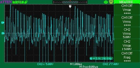
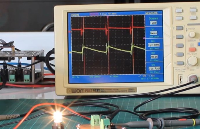
Ref: Chris's Non-Inductive Coil Experiment

Ref: Chris's Non-Inductive Coil Experiment
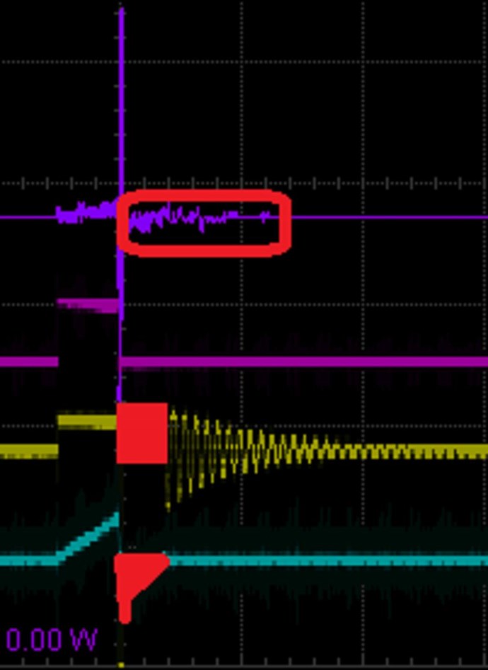
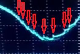
I have shown, a 10% Duty Cycle, on Time, and 90% Off Time, yet we get output through the entire 90% of the Off Time, when the Mosfet is Off, and actually sending Energy Back to the Input, already shown:


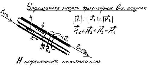
Ref: The Input Coil
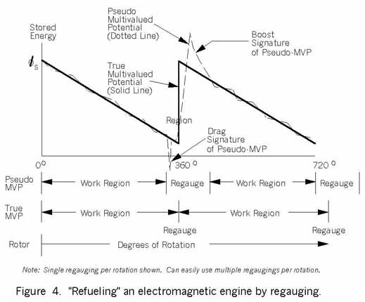
Which as we all know, is Asymmetrical Regauging:

Ref: Asymmetrical Regauging
I am horrified and shocked that Smudge is so certain, in his mindset, that this Statement had to be made! This is the root cause of Dogma! We have undisputable proof that Smudges Statement is Naïve at best and False at minimum!

I just cant believe this sort of mindset still exists! Many here have seen the same as I have just shown! Many here have the same evidence I have just given, and this is the problem we face, in TOO Many peoples Mind, it cant be done, yet the proof shows, unequivocally, it can, its easy and cheap to reproduce!
Ask yourself: Is this Statement not the very Basis of Above Unity Machines at its Root? So to disbelieve, makes Above Unity Machines Impossible for the individual to reach the Goal, in the first place, does it not? Because one has already Ruled out the very means for Above Unity Machines! This mentality of: Something for Nothing is a display of Ignorance, for Energy is still Conserved in Above Unity Machines, its simply the case, we have another Source of Energy we have introduced into the Machine that the very Actions of a Magnetising Current brings about in the first place! Importantly, this Magnetising Current does not need to be from the Primary Coil!
Historical Evidence shows: Floyd Sweet put 33 micro Watts in, and got 500 Watts out, so is this not evidence enough? In his later machines, Zero Input, 5KW Output, and the Statement made is now sounding sillier and sillier!
Smudges statement should read:
The difference between Input magnetizing field energy and Output magnetizing field energy is where Above Unity Machines fall within reach.
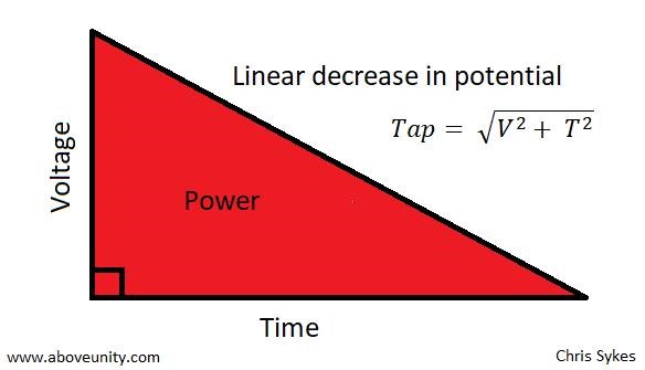
The fact of the matter is simply, Current I through Turns N, is a Magnetising Force, known as Ampere Turns NI. Ampere Turns NI, requires a specific Energy. This Energy is Mathematically defined by Ohms Law, as the Coil Impedance Z can be used as R, and the Voltage V, between the two Terminals, can be calculated: I = V / Z, or given we know the Current, P = I2 x R, either way, we only need two accurate values, to determine the others, for an accurate Energy Result.
That's why I have had to slowly bring information out, to help others see Truth!
In Time, this will become main stream and everyone will accept it as evidentiary, but that time is still a ways off yet!
Best Wishes,
Chris


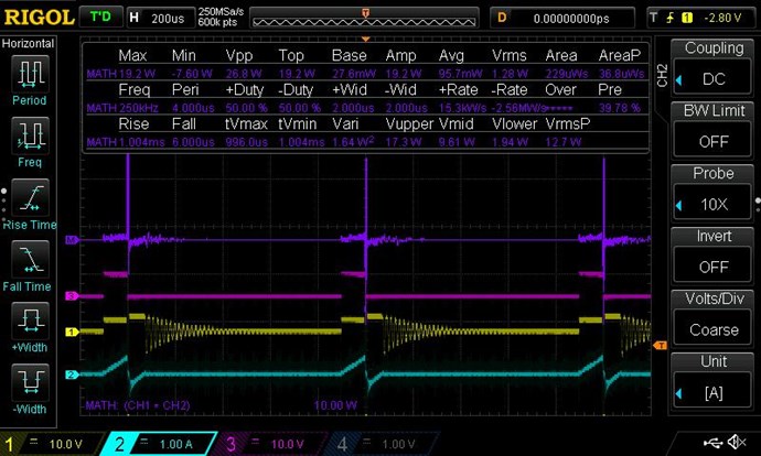


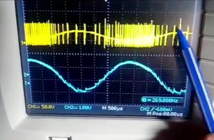
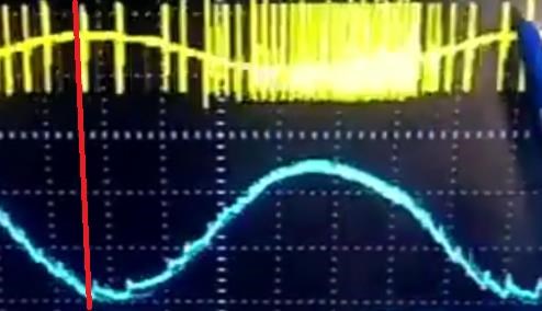
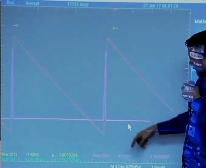


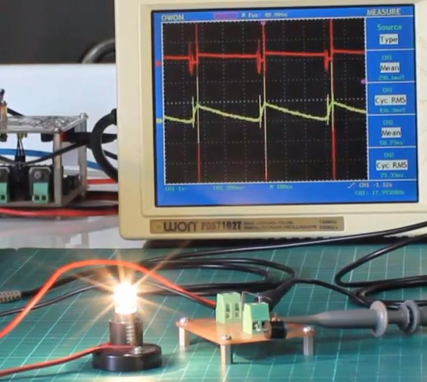

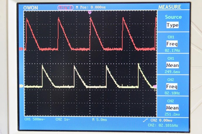

 as you notice, we take into account here the duty cycle and the frequency T=1/f


 .
.


