MEG (Moitionless Electromagnetic Generator)

  • Topic Is Sticky
  • 975 Views
  • Last Post 29 October 2021
Heliarc posted this 14 October 2021

Hello.!!!Got my Cree mosfets ready and mounted to a heatsink. Waiting on the pulse gen and got to still make the mosfet driver board up so I can drive it. I will probably rewind both of these with some thinner wire on outputs.

Anyone else doing/have done a meg? Any tips or ideas?

Cores are AMC 320 and AMC C25 Mosfets, Cree C3D version.

So far I have two wound cores.. using 20ga initially on smaller core and 16ga on larger core.

Wire is wound at about a 1:4 ratio to the input and output.. to try and keep voltages low.

I'm currently awaiting more gear get formally started with the pulses. I was going to replicate Naudlins board model but decided to go with a more, vicious approach with high powered mosfets. I've analyzed the pole positions for polarity so I can change the shift to one direction or the other on both coils.

I should have the equipment to formally start in about a week.

I will be checking power quality and shape with a oscilloscope soon as I get it firing.

Attached Files

  • Liked by
  • Chris
  • Shadow_
Order By: Standard | Newest | Votes
Chris posted this 14 October 2021

Hello Heliarc and welcome!

Can you please add more information to your first post. Give us an idea on what your goals are, where you are at, circuits you plan to use, you get the idea, more information is always better!

We have a MEG Thread here already: The MEG - Tom Bearden

Replications should be in the Replications Category also.

Best Wishes,

   Chris

P.S: Help using the Forum will show you how to Upload Images and so on, there is a lot of easy to follow information in there!

  • Liked by
  • Shadow_
Heliarc posted this 24 October 2021

So I did some testing. It did not seem sucessful.

One thing I noticed.. was one side of the core seemingly became saturated. And one output side would generate a heavier voltage and current.

I have my coils cross pathed. So if I put them on the same top side together it may give better effects. But as I loaded one side...after a time it would lose current and would shift to other side.

I was measuring a max of 200v dc on output rectified. The current would rise to around 0.4a and voltage drop under a load. But so many things changed when I did different things. It would take a long time to truly figure it all out.

I did notice when I tried to put a free wheeling diode in place...it got quiet... power dropped... so that tells me somehow the back emf helps the output?? Or I may be thinking to far out.

If I could redirect the emf into a capacitor.. or in turn reuse it in energizing the coil it might help.

  • Liked by
  • Chris
  • Shadow_
Chris posted this 25 October 2021

Hello Heliarc,

First, if I may ask, please post some Images so we can get a better idea on what you're doing, this would help immensely! Videos, also very helpful! 

I agree with your analysis thus far! I saw similar results in my early Replication!

Treat each Coil with its own set of rules. Make each Coil an individual Coil, in an individual Circuit! This is Diakoptics, used by the great Gabriel Kron! This is System Analysis:

In systems analysisDiakoptics (Greek dia–through + kopto–cut, tear) or the "Method of Tearing" involves breaking a (usually physical) problem down into subproblems which can be solved independently before being joined back together to obtain an exact solution to the whole problem. The term was introduced by Gabriel Kron in a series "Diakoptics — The Piecewise Solution of Large-Scale Systems" published in London, England by The Electrical Journal between June 7, 1957 and February 1959. The twenty-one installments were collected and published as a book of the same title in 1963. The term diakoptics was coined by Philip Stanley of the Union College Department of Philosophy


All here are familiar with the term.

Before long, you will arrive at this Circuit:


The Input Coil: L1 can be High Side, or Low Side Switched.

When you have the Polarity correct, you will get a Waveform similar to this:


This is Asymmetrical Regauging, we have many pages here on this Forum explaining and showing Experimentally, how to do this!

At the ideal Tuning, we get Magnetic Resonance, this is where Power Gains of Greater than Unity are achieved, thus the name Aboveunity!

If you read, and make effort to understand the pages HERE on this Forum, these experiments are Very Easy and Very Cheap!

Best Wishes,

   Chris

Heliarc posted this 26 October 2021

Hey thanks for all that!! I have a very hard time loading the website . And also have hard time loading images. My OP above I attached a image but it does not show up like yours do. Do I paste the images into the text box? I am only able to log in every so often. I get the error messages of timing out alot. Here is a link to my YouTube channel. I am not as organized as many of the people here. But it's just a hobby I throw together from time to time and do different things..


These are latest videos I made. I have more on my channel. I also build really strong lasers as a hobby. I have not yet achieved any spectacular results (that I can see). I'm getting 800v PtP and closed or even a resistive load drops it down to like 4v. But I do receive decent current 0.40a out of output side. The side I get best output gain is proportional to the way I connect the input coils. It will favor one side or the other.

  • Liked by
  • Shadow_
  • Chris
Heliarc posted this 26 October 2021

I really appreciate the advice. I am going to order some better resistors so not using a light bulb as I believe it's slightly inductive... And also will order a MOV. Although I'm not sure what voltage rating or what to do once it's in paralell to the coil. Other than gaining measurments... I assume maybe I can make a circut to collect when the MOV is closed to collect the amperage and voltage spike.

Thanks

PS.. i had to split and post these seperate. Kept getting a post error. May have done something wrong. Worked this time tho!

  • Liked by
  • Chris
Heliarc posted this 26 October 2021

While I'm here, I also wanted to add some things I did notice.

I sweeped the frequencies with one coil alone..around 3.6khz I noticed the resonant frequency as described in this forum and reading as the amplitude got higher. (And peaked) I am still going to work with both of them to try and get that frequency too. (With both firing 180° out)

I have gotten pretty high open voltages out of it. When I go lower It will draw more current.

I realized right away there is a ton of variables I need to address and get a planned path of moving forward.

The coil gets extremely loud. I may have some back emf interfering with the mosfets at certain frequencies although I did add a little diode to the positive leads. The mosfets as I understand have build in blocking diodes.

I used a 10kohm pull down resistor at the Gate to S on the mosfets.

I have not yet added any HV capacitors to the input or output coils. And I will.

I also noticed when I put a flyback diode in the input coils...Input current drops and overall all activity is lowered. I'm not sure if the back EMF is good for a meg, or not.

I'm going to get on my laptop tonight and read alot about timing. I read on reddit where a guy had an idea with a meg to use something similar to a tank circut, with a trigger coil placed on it to try and get it to "ring" on its own. This is a bit above my threshold of knowledge, as I am not sure what was intended to be done by that. I assume having a small coil nearby signaling a mosfet or something while accounting for its voltage to the gate?

If you have any direct suggestions that I could add, or subtract or to do to get more results, please do!

I am sure I will find some things I can do whilst reading on the forum!

Chris posted this 27 October 2021

Hey Heliarc,

Great work! Thank You for Sharing!

Your Output should be a Sawtooth Waveform, which you will get if you follow the Circuit I gave, here is the MEG Team Waveform:


From The MEG Team Demo Video:


Yes, I am sorry, the website is slow at the moment. The Internet Connection I have is very bad! I have ordered Starlink, speeds will be very much faster! I hope it arrives soon!

Re Images and so on: Help using the Forum will show you how to Upload Images and so on, there is a lot of easy to follow information in there!

I am sorry for the slow issues from time to time! I hope soon we will be very fast!

Best Wishes,

   Chris

  • Liked by
  • Heliarc
  • Vidura
Heliarc posted this 27 October 2021

Thanks!! I will look at the help section.

I've actually seen those videos before. I refer to them occasionally for hope. Lol

I also have a video from bearden where he really explains and breaks it down as well. It's a video that mysteriously vanishes from YT every so often.

Oh, and so my goals. Myself, like many others would love to find a easy method to get free energy of course. Although nothing is free. I spent alot on all the materials and such as everyone else does.

But even if I (we) cannot close loop it.. the fact that you could amplify energy for use potentially would greatly help 3rd world countries and even off grid applications here where I am.

But..for the most part it's a hobby. I'd love to prove some colleagues wrong.

I have a very strong interest in your circut you show with the 3 coils. I am skeptical if I should order a few more cores and just do some other experiments like those without magnets. I probably will grab another core or 2 when I place the mouser order for mov.

Chris posted this 27 October 2021

Hey Heliarc,

Once one understands this technology, it is VERY easy, and can be very Cheap! Its getting there is the battle! A battle I have also faced and won simply because I refused to give up! Don't give up!

The name: "The MEG" is true and correct! It is a Motionless Electromagnetic Generator!

Each Output Coil is a Generators Rotor and Stator Coil, each is each others Source! The big Power Coils must Buck Each other! Opposing Magnetic Fields!

If one can understand this thinking, then the battle is half won!

Best Wishes,

   Chris

Heliarc posted this 29 October 2021

I've been digging into Asymmetrical reguaging the past few days alot. I decided to do another test before I order more things.. I did a heavy load, and hard input test. Input was max PS (18v 3.5a) same two coils 180° out of phase, with the load being the 2, 21w lamps on the output. 860hz. Pulse. Measuring both with ossiloscope and I actually got a sawtooth!!! I didn't record the second part, but as I went up in frequency from there, 860hz, I noticed the sawtooth would slowly build up but would still illuminate the lamps. It was neat to see. I'm assuming it's the voltage climbing in the coils to where it wants to be under load.. Or it's a artifact of the scope. I also added a 1000v capacitor on one end open, and voltage would stable out at about 520v on the scope. Here is the video of the sawtooth..

Chris posted this 29 October 2021

Hey Heliarc,

Great Work! Thanks for sharing!

If you can check your polarity, as this Exponential Curve is not yet, quite, right.


You're very close! Remember, Each Partnered Output Coil must be in resonance, so Input must be tuned for this sweet spot!


The Linear Region is the Work Region, where your Output Coils BUCK each other and do Work!

In my work, you can also see this:

Ref: Chris's Non-Inductive Coil Experiment


Don't forget, Resonance, the Machine may get somewhat noisy at resonance!

I +1 your video and left a message, but now see on page refresh, my message is gone. Typical YouTube!

Great Work and again, Thanks for Sharing!

Best Wishes,

   Chris

Heliarc posted this 29 October 2021

Ah I see. So not quite the phenomena yet!!!

I'm going to order a smaller core, and do some experimenting with resonance without a magnet.. and maybe also play with torrordial coils. I have a few old inductor rings of a broken buck converter.

Thanks for all the graphics.

Do you know if anyone in the group has successfully made the MEG? I saw your posting with what appeared 1.3COP.

Just curious. I'm probably going to rewind my large coil very soon. I have a feeling my angled coil windings may not be ideal the more I think about it. For awhile I though maybe it could capture more Flux on the outer edge but it could cause interference.

I really appreciate everything you mention!

Chris posted this 29 October 2021

Hey Heliarc,

Yes, the Magnet is a Red Herring. Yet can play a role later on once one has made steps ahead! I would keep the Coils / Windings you already have and experiment with that!

Many here have achieved great success! Many are modest and try not to admit their success publically, or boast of great achievement, yet, all here are happy to share what they have learnt, this is the sign of a truly Humble Person!

I believe in Free Will, I am not and never will, apply forced indoctrination on others, all here, are here of their own free will and because they feel something is right, true and correct here! What the other forums have missed entirely!

Some here have built the MEG but I will be honest I do not know the results, I believe many reasons exist for this.

Once one has learnt the basic rules to this technology, you would be surprised how many machines this technology fits the criteria to bring about the Above Unity criteria! The basic Concept is the same across many machines!

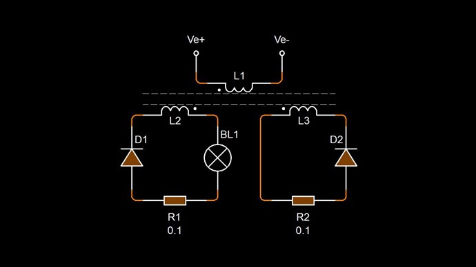
The Total M.M.F of the Secondary Coil, the Amps through Turns NI, Ampere Turns, in any Conventional Electromagnetic Machine is entirely wasted!

We use this M.M.F and make this M.M.F do Work for us! This way, our Input is reduced by a factor of magnitude, which is entirely dependent on the total Magnetic Flux Φ, which is easily manipulated to be increased for the same Current I, up to a point.

While the other forums pride themselves on building all sorts of fancy Circuits to achieve a Goal, they still do not know what the Goal is! Therefore, the Circuits are a waste of time and energy! They achieve nothing! The Circuit becomes a relic and is no good for the end Goal!

In depth study of the Electrical Generator and what exactly Voltage and Current is will yield Direction and then one can focus on how to invoke Voltage and also Support a Current! Then any formula that fits this criteria will give Circuit Design and will result in useful progress!

The ideal path forward is Cheap and Simple! Minimum Parts, minimum Assembly, minimum Cost, maximum Simplicity! This is where Success lays!

Magnetic Resonance is Maximum Voltage, Current and Magnetic Field. Your Input is only the Excitation, that's all! Faradays Law applied Asymmetrically!

Best Wishes,

   Chris

  • Liked by
  • Jagau
  • Shadow_
We're Light Years Ahead!
Members Online:
What is a Scalar:

In physics, scalars are physical quantities that are unaffected by changes to a vector space basis. Scalars are often accompanied by units of measurement, as in "10 cm". Examples of scalar quantities are mass, distance, charge, volume, time, speed, and the magnitude of physical vectors in general.

You need to forget the Non-Sense that some spout with out knowing the actual Definition of the word Scalar! Some people talk absolute Bull Sh*t!

The pressure P in the formula P = pgh, pgh is a scalar that tells you the amount of this squashing force per unit area in a fluid.

A Scalar, having both direction and magnitude, can be anything! The Magnetic Field, a Charge moving, yet some Numb Nuts think it means Magic Science!

Message from God:

Hello my children. This is Yahweh, the one true Lord. You have found creation's secret. Now share it peacefully with the world.

Ref: Message from God written inside the Human Genome

God be in my head, and in my thinking.

God be in my eyes, and in my looking.

God be in my mouth, and in my speaking.

Oh, God be in my heart, and in my understanding.

Your Support:

More than anything else, your contributions to this forum are most important! We are trying to actively get all visitors involved, but we do only have a few main contributors, which are very much appreciated! If you would like to see more pages with more detailed experiments and answers, perhaps a contribution of another type maybe possible:

PayPal De-Platformed me!

They REFUSE to tell me why!

We now use Wise!

Donate
Use E-Mail: Chris at aboveunity.com

The content I am sharing is not only unique, but is changing the world as we know it! Please Support Us!

Thank You So Much!

Weeks High Earners:
The great Nikola Tesla:

Ere many generations pass, our machinery will be driven by a power obtainable at any point of the universe. This idea is not novel. Men have been led to it long ago by instinct or reason. It has been expressed in many ways, and in many places, in the history of old and new. We find it in the delightful myth of Antheus, who drives power from the earth; we find it among the subtle speculations of one of your splendid mathematicians, and in many hints and statements of thinkers of the present time. Throughout space there is energy. Is this energy static or kinetic? If static, our hopes are in vain; if kinetic - and this we know it is for certain - then it is a mere question of time when men will succeed in attaching their machinery to the very wheelwork of nature.

Experiments With Alternate Currents Of High Potential And High Frequency (February 1892).

Close