Lenz law on POC

  • 1.6K Views
  • Last Post 08 June 2022
Amin posted this 28 August 2021

Hello friends,

In below picture we have Square pulse generator with 10% DC

We have two coil L1 Primary and L2 Secondary with R load and diode.

I marked question mark in the second table, so what is happening on that stat?
Lenz low on POC1

if something wrong in pictures , Please let me know.

Please help to understand it

Regards
Amin

Order By: Standard | Newest | Votes
Chris posted this 28 August 2021

Hi Amin,

From a Symmetrical point of view, Two Coils, Two Magnetic Fields, Equal and Oposite, Symmetrical, It is not possible to have a Lenz's Law Offset.

Each Magnetic Field, M.M.F, is Equal and Oposite, they effectlvely Cancel.

One needs to Expand on your diagram and think about the Machine Asymmetrically to gain a Lenz's Law Offset.

I posted, some posts back, a proceedural outline:

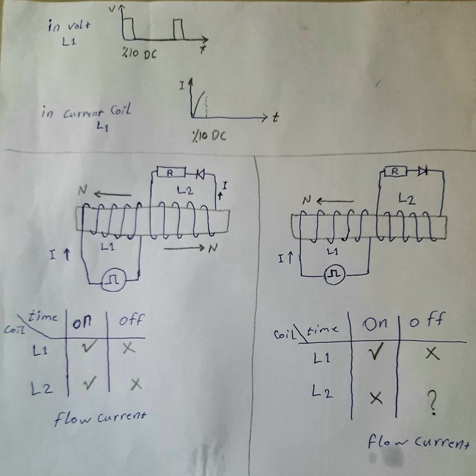
At Time t = 0: we have no Conduction in all Coils in our machines. No Current Flows.

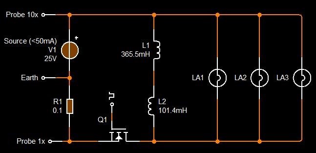
At Time t = 1: we have Input Coil Conduct with the Switch On of the Mosfet, Current Starts to Flow.

At Time t = 2: we have Electromagnetic Induction between your Input Coil and POCOne , POCOne Conducts when the Diode Voltage is at threshold Voltage, normally 0.5 to 0.7 Volts.

At Time t = 3: we have Current Flow in POCOne, this Current starts to Change in Time also, Electromagnetic Induction occurs between POCOne and POCTwo.

At Time t = 4: we have POCOne's Current induce sufficient Voltage in POCTwo and then at 0.5 to 0.7 Volts, POCTwo then Conducts.

Here you can see, we have a Delay in Conduction, the Coils are delayed in Time T, and as a result, they Slap Together, which is Electromagnetic Induction in your Machine for a Second Time!


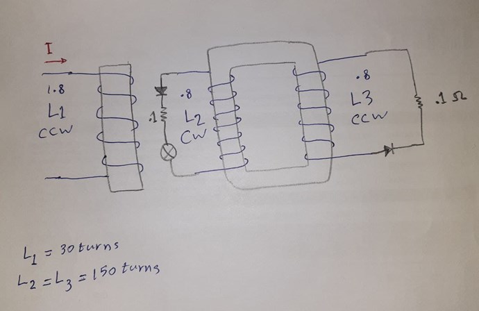
Accounting for each Instance of Electromagnetic Induction in your machine, you have 180 + 180 = 360 so your Third Output Coil opposes your Second Output Coil but is Assists your Input Coil.

So the best way to think about this is in terms of Force, M.M.F, the Current I through Turns N in each Coil, In a "Generator" this is responsible for Shaft Torque. This Force is negated by POCTwo, your Second Output Coil.

Here we have a Magnetic Field that is offsetting Lenz's Law by a Factor of Magnitude, because the three Magnetic Fields are Asymmetrical, we have Force Assisting our Input Coil, the Input is bought down as a result.

Please take the time to study this in depth, as once this is properly understood, a whole new Science opens up, making current thinking obsolete and antiquated!

Best Wishes,

   Chris

Amin posted this 29 August 2021

Hello Chris,

my understand is:
   At On time of duty cycle occur all time t=0 until t=4 and then during Off time of duty cycle will continue t=3 and t=4 repeatedly.

Please let me know my wrong understand.

Amin

  • Liked by
  • Chris
  • Augenblick
Chris posted this 29 August 2021

Hi Amin,

No, Input is pulsed only once per Cycle.

Output, each Partnered Output Coil has two Separate Reactions.

Each Output Coil sees the other as its Source or as its Primary. Input Energy is just a Catalyst for the Output Coils. The Output Coils are the very same analogy as a "Generators" Rotor and Stator Coils:


The Input Coil simulates Shaft Rotation, if you like, with very little Torque on it when running correctly.

Why is a Transformer not Above Unity? Because the Input is 100% Opposed by the Secondary: Equal and Opposite Less Losses, so change this, and we have what I wrote in the above Post.

One needs to have Coils in Resonance, 180 Degrees out of Phase and approximately equal in Magnitude. Magnetic Resonance.

Best Wishes,

   Chris

deleted posted this 31 August 2021

L2 in the right drawing has become a like flyback converter:

During T_on, a voltage builds on L2 but diode is blocking, when T switches to off, magnetic field collapses, potential on L2 reverses, the diode conducts and current is allowed.

Chris posted this 31 August 2021

L2 in the right drawing has become a like flyback converter:

During T_on, a voltage builds on L2 but diode is blocking, when T switches to off, magnetic field collapses, potential on L2 reverses, the diode conducts and current is allowed.


Hi Alannn,

I think you would be surprised, technically, no, this is not correct, although at first glance, this is an assumption many do tend to come up with.

This total process all occurs at TOn, and during the OnTime Delta. No Fly Back occurs here!

All this can be seen in Experiment very easily! Observation is Key and our Observations are crutial to making progress, Assumptions are never of any bennifet and have done nothing but got the Human Race into strife!

When one has the right conditions, we have two Outputs where a Conventional Transformer has only One, two Outputs at 80% efficent each = COP of 1.6 due to the fact that 2 x 80 are 160.

Just a tiny push in the right direction, and we have made massive advances in the right direction.

Best Wishes,

   Chris

  • Liked by
  • Shadow_
  • Augenblick
deleted posted this 31 August 2021

Yes agreed there is no flyback in the original 3 coil POC, I didn't make it clear it was a reply to Amine's question, in the drawing, the setup on the right has only two coupled inductors and a diode, which makes it a  flyback converter (wiki), when dphi/dt is positive, no current is allowed because of the diode, so the flux energy is "stored" in the core, when the flux collapses, polarity of EMF reverses because of -dphi/dt, then the energy is dumped into the L2 circuit because the diode now conducts and current is allowed.

I thought I understood the POC, but am not sure anymore. I'm looking for an abstract understanding.


This is interesting too, it's what Bearden tried to tell us from the start, but the conservation dogma being applied ruins everything.

Amin posted this 20 September 2021

Hello Chris,

I did POCs configuration over TV core like this pic:
Note: L1 is over L2, I draw separate to show clearly:
TV core POCs schematic
also you can see this video from my circuit:

Best Wishes,
Amin

Chris posted this 20 September 2021

Hey Amin,

This is great Work! Well Done and Thank You for Sharing!

Now, you have the concept right, all you need do is improve on it. Find Magnetic Resonance, each POC 180 Degrees out of phase and Equal in Magnitude but Opposite in polarity, like you have seen. To do this, adjust Frequency and Duty Cycle. Maximum Output Voltage is Resonance. B and I are Also Max. Input drops to minimum!

It is worth studding Others Successes also to get more information.

This is great Work, you only need improve on it now, the concept you already have!

Improvements include Larger Cross Sectional Area, reducing your Coil Length, B is higher the shorter the Coil, and watch turns, E.G: Length of each Coil.

Antenna Theory is worth studding, we have all this information here on this forum.

Please see: Builders Guide to Aboveunity Machines, for all links and guides.

Best Wishes,

   Chris


P.S: Also, please dont forget, you have Power in Both Partnered Output Coils! Currently we are only measuring one of them, the loaded one, no one has measured the other one and added this to the Output Total! cool

Be proud of yourself My Friend!

Amin posted this 16 October 2021

Hi Chris,
I hope everything is good.

L1 coil length is 2 meters  and L2=L3 is 8 meters
I tried to find magnetic resonance by:
         1- changing frequencies with one step.( from 1 ~ 250kHz )
         2- changing frequencies with different duty cycle ( 10% , 12%, 25%, 30% )
         3- increase load by adding another same bulb and applied frequencies and duty cycle.
 
I changed L1 turns from 30t to 23t and applied frequencies and duty cycle
I couldn't find magnetic resonance yet.

so please let me know if I need to scan frequency again, I will programming my signal generator for sweep square wave frequency automatically.

I have question:
in my circuit, the gap of core is center of coils. ( I think magnetic field is not complete in each coils )
and I saw Fighter circuit, the gap is not in center of coils.


so let me know which one is correct?

Best Wishes,
Amin

  • Liked by
  • Chris
  • Augenblick
Chris posted this 16 October 2021

Hey Amin,

The Image is Fighters ZPM, and his thread: Romanian ZPM (Zero Point Module)

Fighter used 150 turns on L2 and 300 turns on L1, respectively.

Duty Cycle was 25%

Frequency was tunned for resonance:


Fighters Circuit is very straight forward


L1 and L2 are connected to Buck Each other, using the Right Hand Grip Rule and Conventional Current.

@Fighter, did you want to add anything to help Amin?

Many of the same similarities are present in My Circuits also, Resonance is required.  The Machines become Reactive at Resonance, all / most, Input Power is sent back to your Source.

Patience and close study of the Coils is key to succeeding Amin! Please let us know your progress My Friend!

Best Wishes,

   Chris

Melendor posted this 16 October 2021

Hello Amin.
Welcome back.
Glad to see you experimenting again.

In the experiment that @Fighter made ( Romanian ZPM ) he used Bucking coils.

Opposing magnetic fields , but his 2 coils are electrically connected to one another.

In the experiments that @Chris , @John , @CD_Sharp , @CaptainLoz made , there is no direct electrical connection between           L1 ( trigger ) , L2 and L3.
All 3 coils share a C core  ( closed loop core ) and are connected by electromagnetic induction.

!!! The change in magnetic field of the L1 will induce a voltage on all coils , and if one coil has a load on it ,  a current will flow into that coil .

Your  core....is ok for start..We have a member with the name of @Skywatcher , that had very very good results with a core similar to yours. Perhaps you can check it out.

However what @Chris has said is true.

You will need in the future a bigger core.
AMCC 200 does not come into the "Big" group,although it cost around 100$.

When you will get resonance.polarities correct ,and you can replicate the experiment whenever you want....you can start saving money and buy one bigger core from China.

@Chris , thank you for all your good work.
Every time I read the forum and see your videos and other members videos,I learn something new.

Some new piece of the puzzle.
There is something to what I can not find a logical answer to : ,

@John , Cd, Captain , You  ,have similar core and windings and you hit resonance around 2 - 5 Khz and upon hitting resonance you got the effect that you searched for.
@Fighter , with the "same" setup as you guys , found the effect at around 650 Khz upon hitting Resonance.

The difference between 5 khz and 650 Khz is that from the Earth to the Moon.
How can it be that with the same core and the same amount of Copper / windings  the difference in Resonance frequency is so high ?

If you got time to answer it would be great.
Hope that others will learn from your answer inkl . me.

Thank you everybody.
Keep up the wonderfull work.

*Melendor the wizard


Amin posted this 07 June 2022

Hi Chric and friends,


I hope everything is good.

I requested from some my friends to buy nano crystal core from china like @Fighter used it. maybe it will be in my hand after one month.
my question is: is there any way to use iron core of normal transformer.

Best Wishes,
Amin

  • Liked by
  • Chris
  • Augenblick
Chris posted this 07 June 2022

Hi Amin,

Yes you can use any Core, but some are what I call Slugs, slow and do not allow change, which can be remedied sometimes by a small gap.

Tinman's RTV3 is an example:


The Core must allow for maximum Change over the optimum Time period.

Also, please read, follow, and understand the thread: Coil Geometry this thread is very important to follow and understand as it means greater success over a narrower spectrum.

Best Wishes,

   Chris

  • Liked by
  • Amin
  • Augenblick
Amin posted this 08 June 2022

Hi Chris,

Last 3 videos are saying: This video is private

Best Wishes,
Amin

  • Liked by
  • Augenblick
  • Chris
Chris posted this 08 June 2022

Hi Amin,

Videos are now Unlisted. Please let me know if you have any more YT inflicted errors!

The Thread related to those videos is: The Rotary Transformer - Tinman

Best Wishes,
   Chris

  • Liked by
  • Augenblick
We're Light Years Ahead!
Members Online:

No one online at the moment


What is a Scalar:

In physics, scalars are physical quantities that are unaffected by changes to a vector space basis. Scalars are often accompanied by units of measurement, as in "10 cm". Examples of scalar quantities are mass, distance, charge, volume, time, speed, and the magnitude of physical vectors in general.

You need to forget the Non-Sense that some spout with out knowing the actual Definition of the word Scalar! Some people talk absolute Bull Sh*t!

The pressure P in the formula P = pgh, pgh is a scalar that tells you the amount of this squashing force per unit area in a fluid.

A Scalar, having both direction and magnitude, can be anything! The Magnetic Field, a Charge moving, yet some Numb Nuts think it means Magic Science!

Message from God:

Hello my children. This is Yahweh, the one true Lord. You have found creation's secret. Now share it peacefully with the world.

Ref: Message from God written inside the Human Genome

God be in my head, and in my thinking.

God be in my eyes, and in my looking.

God be in my mouth, and in my speaking.

Oh, God be in my heart, and in my understanding.

Your Support:

More than anything else, your contributions to this forum are most important! We are trying to actively get all visitors involved, but we do only have a few main contributors, which are very much appreciated! If you would like to see more pages with more detailed experiments and answers, perhaps a contribution of another type maybe possible:

PayPal De-Platformed me!

They REFUSE to tell me why!

We now use Wise!

Donate
Use E-Mail: Chris at aboveunity.com

The content I am sharing is not only unique, but is changing the world as we know it! Please Support Us!

Thank You So Much!

Weeks High Earners:
The great Nikola Tesla:

Ere many generations pass, our machinery will be driven by a power obtainable at any point of the universe. This idea is not novel. Men have been led to it long ago by instinct or reason. It has been expressed in many ways, and in many places, in the history of old and new. We find it in the delightful myth of Antheus, who drives power from the earth; we find it among the subtle speculations of one of your splendid mathematicians, and in many hints and statements of thinkers of the present time. Throughout space there is energy. Is this energy static or kinetic? If static, our hopes are in vain; if kinetic - and this we know it is for certain - then it is a mere question of time when men will succeed in attaching their machinery to the very wheelwork of nature.

Experiments With Alternate Currents Of High Potential And High Frequency (February 1892).

Close