Kritischer's Non-Inductive Coil Experiment

  • 1.4K Views
  • Last Post 17 January 2021
Kritischer posted this 27 December 2020

I'm a little embarrassed to say that I've done nothing but fail at all my attempts to go AU since 2007. I'm prone to step right in the mistakes my forbearers warn me about explicitly and my ambition far outweighs my ability. My only strength is that I can't help but want to continue to fail forward and try learn from everything that doesn't kill me. One thing all successful people have in common is failure so my approach is to be such a absolute glutton for failure that I stop noticing the sting of disappointment... until there's nothing left but success. 

Since I found this group I don't feel so alone in these endeavors so it just wouldn't be right if I didn't share this attempt.

I'm grateful for this group and would like to solicit feedback conditionally... Please do me a favor and just don't say this stuff "simple" or "easy". It's not. It may seem that way once you already know it. The same concepts, techniques, and applications all may have varying levels of difficulty according to who the student is. I know someone else can get this right the first time in a matter of hours while it's taken me months to get this far even though everything is all right here.

I'm Kritischer, and I'm done going down the Rabbit hole on my own...

Core is Hitachi AMCC0100

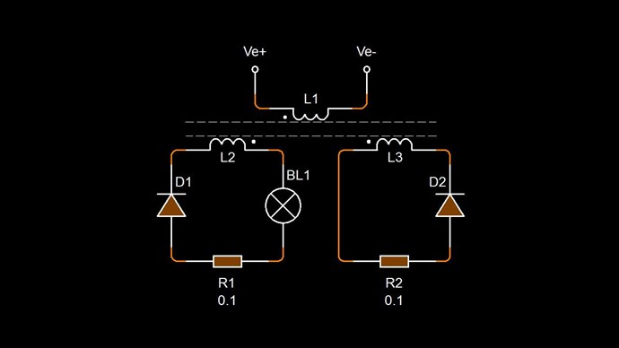
Excitation primary is 22AWG, comprised of 4 parallel wires tied at the ends and then wrapped 6 times Anti-Clockwise going left (ACWL). I opted for this over thicker wire because it's easier to work with, parallel resistances & inductances decrease, I had to start somewhere, and why not?

1st and 2nd Secondary's are 23 turns. I realize now that one should probably be longer.
The 1st Secondary (left) is Clockwise going from left to right. I think this is the load coil.
The 2nd Secondary (right) is Anti-Clockwise going right to left. I think this is the assist coil.

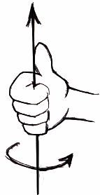
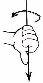
This clockwise/anti-clockwise right hand rule left hand rule stuff is maddingly ambiguous the longer I stare at it and is incredibly fundamental and important I know. I wish I could strike the idea of current going positive to negative completely from my memory. I feel like I MUST visualize current as a phase conjugate starting from the wire end opposite the highest NEGATIVE charge but when I add coil direction to this I realize that I'm painfully disinclined mechanically.

Before I wound this thing up I spent many hours trying to make it right only to realize afterward that I never get it right the first time. I tried making a calculator to calculate current based on some wonderful pigeons calculator. His commentary is hilarious.

My plan was to  sweep for resonance and then use the time of the 1/4 wavelength at resonance as the pulse width for the primary. I couldn't do it. I tried sine sweeping the secondary's for resonance and didn't see a defined voltage peak. I tried driving from the middle like I think Chris's video shows but I don't think I have enough turns and I just don't know any better. I didn't see the outputs go out of phase either.

So I said f*ck it and put together a pulse driver from some modular electronic components I was using for the Arduino Project I'm going to hopefully someday be able to share.

Someday... 

But for now...

I put a toggle switch in this handy little PWM Generator

 Connected the PWM output to this optocoupler/mosfet driver

Which got it's power from this DC-DC buck/boost converter

I was originally using a 6V battery as a power source but moved to a DC power supply. I kept the buck/booster in the mix because I didn't see the harm in getting familiar with gain staging with it.

So the setup started to look something like this

Trying not to get overwhelmed with analysis paralysis I followed the advice to break it down.

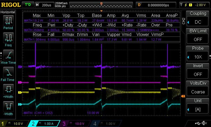
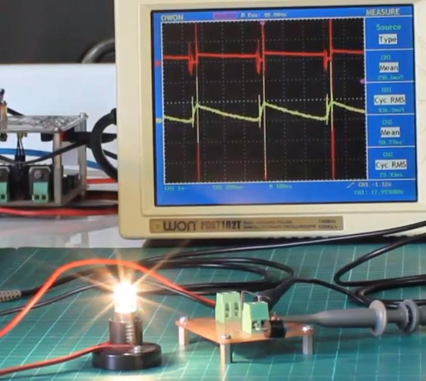
I started pulsing and looking at the voltage first to make sure I could get sharp pulses on the excitation coil (blue). At this time I think the yellow was the left coil with a diode and 1ohm resistor shorting it. note the 100x multiplier.

I connected a 7W lightbulb directly to the signal driver to see if I could get it to light up.... not so much....just a dim glow.

Next I tried step 2 and tried to get the light to glow dimly across the left secondary. only 2 coils were connected at this point... I couldn't get it done.

This is where I started questioning everything from the direction of the diodes to the windings to whether I should be using the left hand rule. I swept from 1% duty as high as 15 from 600Hz to about 5Khz adjusting the voltage to the excitation coil all while keeping an eye on the power supply to make sure I didn't go any higher than .5A.

At this point I'm tired and don't have what settings went along with with what scope plot but I kept on trying different things trying to see if I could eventually get a knack for it. I've been doing that for 2 days now.

Something felt right about the above but I have nothing to back it up. I have nothing to back anything up really.

I've been taking current measurements across a 1Ω high power "no inductance" resistor and a switching diode. I don't have 0.1Ω resistors yet. Soon.

I've been placing the diode at the ends of the coils with the line closest to the end of the coil because I want the current to travel towards the center. I've been placing the probe positive on the side of the diode closest to the coil. I don't know if this is right.

At one point I was putting in 6V and was getting out 21V or so on the left secondary (load?) coil. At that point I connected a 10V TVS across the right (assist?) coil. Nothing noteworthy happened... but that's not to say anything I've done up to this point makes one lick of sense.

I have to hang it up for the night. Sadly there aren't enough hours in the day and I have limited hours to work on this despite it literally being the most important thing anyone with the means and motivation to do it should be doing.


Order By: Standard | Newest | Votes
Chris posted this 27 December 2020

Hello Kritischer,

Very nice work! Thank You for sharing! Don't worry, I fail, even now, sometimes an idea is not always as easy as it seems in ones mind! Failure is part of the path of learning.  

So far, this is great!

First recommendation, study the thread: The Input Coil

It appears your Input is staying on, well after the switch off, this needs to be resolved. Input, where the switch is, once the switch ( Mosfet ) is closed, there should be no current flowing from the input, is there is, and it appears there is, there is a problem! You need to work on the Input, making sure, the Input is totally off when the Duty Cycle has ended.

Another thing, Your Input Coil and one Partnered Output need a closer Coupling, wind your Input Coil on top of one Partnered Output Coil! Make sure this Partnered Output Coil is in Transformer mode, direct Coupling to the Input Coil.

Make sure, all Coils are Loaded at all Times!

Your Thumb, the Right Hand Grip Rule, make sure your Thumb is in the Direction: 1 + -1 + 1

Conventional Current, from Positive to negative.


Of course, your Partnered Output Coils must oppose at all times! E.M.F must be induced from the Partner:

  1. Input Coil opposes POCOne
  2. POCOne opposes POCTwo
  3. POCTwo Assists your Input Coil!


You are doing a good job! Keep it up! Do not change anything else except the few things I recommended. Coupling is important!

Think of it this way, Transformer is 85%, you only need to add 15% to get to Unity! Any extra is: Above Unity!

Thank You for Sharing! This is great work! Document everything, here is you need to! Video, Images and Text. So you don't forget it. Remember, little steps for little feet!

Best Wishes,

   Chris

Kritischer posted this 28 December 2020

once the switch ( Mosfet ) is closed, there should be no current flowing from the input

This makes sense and should have been obvious. I thought the diode on the output of the mosfet was supposed to accomplish this. I'm not sure I know how to remedy this since I'm using a pwm/mosfet module.


Maybe I can put another mosfet on the dc +/- input of the module that opens when the signal goes low. Maybe that is overcomplicated too. Is there another way you can think I might try for that?

Yes I will definitely resolve the coupling from primary to 1st POC by winding one over the other. I just need to make sure I do that right... windings in opposition on those two correct?...

Thank you for the support and suggestions 


Chris posted this 28 December 2020

Hey Kritischer,

Probe the Mosfet Gate to see what the Gate is doing. Make sure the Gate is off at the right time.

It may be needed that a 1K resistor may be needed from Gate to Ground, or something similar.

Try placing your Mosfet on the High Side of the Circuit, sometimes this may help the Mosfet turn off correctly. You should see Current similar to this:


See The Input Coil to see the significance here. Positive Voltage x Negative Current = Negative Power.

Yes, increasing the Coupling, and finding the best, Resonant Frequency, where Max Current can be seen, and Zero Reactance achieved, means you have an Output Circuit working correctly.

Make sure you have the Coupling right, worth learning more and more here by playing around with the best combination. Like I said before the best combination I have found is:


  • Input Coil opposes POCOne
  • POCOne opposes POCTwo
  • POCTwo Assists your Input Coil!


Where your Input Coil is wound on top of POCOne.

Best advice I can give is: Have fun! This is the most awesome and fun thing! Its a new world and we are on the Cusp of amazing things! What I have shared is just a Toy, but far more than any other forum has ever provided! Much greater outputs can be achieved and other technologies can be gained from this work! We are at the start!

Best Wishes and Thank You for sharing!

   Chris

Kritischer posted this 29 December 2020

Probe the Mosfet Gate to see what the Gate is doing. Make sure the Gate is off at the right time.

It may be needed that a 1K resistor may be needed from Gate to Ground, or something similar.

What terms can I look for to help with this? 1k from gate to ground doesnt do anything but i know it was just a suggestion. What could "or something similar" mean? I just spent over an hour trying to find the right search terms after spending an hour trying to figure out if probing the gate actually tells me anything.

Mosfet Datasheet

 I know this isn't circuits 101 but this is a showstopper for me.

Chris posted this 29 December 2020

Hey Kritischer,

On your board, you currently have a 10K Resistor pulling the Gate Down. Probe the gate before you do anything!

The 3 digit SMD resistor code 103 stands for 10 kΩ


Here is your layout: SMF Mosfet:


If your Gate is Low, Zero Volts when you want it to be, then the problem is not here.

Best Wishes and Thank You for sharing!

   Chris

Kritischer posted this 29 December 2020

The only thing I seem to be able to improve is done by putting a 330ohm resistor between the drain and one of the grounds

OP

Chris posted this 29 December 2020

Hey Kritischer,

Yes, there is some slow turn off time in there! The Curve is not desirable! Un Solder the 10K Resistor and solder a 1K or 330 Ohm Resistor in place and re-test.

Best Wishes and Thank You for sharing!

   Chris

  • Liked by
  • cd_sharp
  • Kritischer
Vidura posted this 29 December 2020

Hi kritischer, The issue seems to be more of general layout of your circuit. It is not likely that the pulldown resistor is the cause, although the gate signal have improved. If you are powering the device and also the driver of the switch from the same source (dcdc converter) you should connect a decoupling capacitor next to the switch, or use separate sources better, the driver IC's usually need 12- 15v for proper operation. Edit: when I was reviewing the images on the PC , I saw that the switch board seems to use a standard optocoupler, these are not designed to drive a MOSFET, it s likely the cause of the poor switching performance. I hope this helps some. Vidura.

Kritischer posted this 29 December 2020

Vidura I'm grateful to have woken up to see your thoughtful comments even though they do serve as a stark reminder that I am very much lacking in practical circuit experience. I hope that after 100hrs of actual bench time I can look back and see good progress and that after 1000hrs I can be as helpful to others as I've seen you be here.

the driver IC's usually need 12- 15v for proper operation

I selected the 60N03 I've been using specifically to be driven from a 3.3v source. Do you have a strong opinion about this being a bad choice?

The issue seems to be more of general layout of your circuit

 I agree. I'm sure the circuit is doing exactly what it's supposed to be doing... for the way it's setup. However... it's setup incorrectly so I can't expect what it to function the way something setup correctly would.


  • Liked by
  • Chris
  • Atti
Kritischer posted this 29 December 2020

Problem -  I realized that I'm sending more than 3V to the gate. The PWM generator output level is based on the input voltage... which is connected to the DC Supply set at a level higher than 3V. It still functions but I don't know if it has damaged the gate.

 or use separate sources

I'll connect a 3V battery to the PWM generator.

you should connect a decoupling capacitor next to the switch

Question: Will using a battery mean that I don't need a decoupling capacitor? For my own development I need to be able to:
-recognize when I need to use a decoupling capacitor
-know what value to start with and where it goes.
If I'm understanding correctly I would just place a .01uF to .1uF cap across the + and - DC source at the switch.


This morning I got rid of the DC-DC buck booster because it's probably adding unnecessary complexity at this stage. I set the power supply to ~4V which powers the PWM generator but was still not getting a clean turn off...

Next I'm going to
- power the signal generator with 3.3V battery instead of the power supply. The buck booster will not be added back. I'll see if the signal looks like I think it should (no downward line transition). If it doesn't then I will replace the 10KΩ resistor at the gate with a 1KΩ.

Question: If that does not work should I remove the other resistor that I think goes to the signal indicator light?

In hindsight I should have just gotten mosfet components instead of this modular thing. When I try to save time I usually waste it instead.


  • Liked by
  • Chris
  • Atti
Vidura posted this 29 December 2020

I recently reviewed, and have edited the last post. The MOSFET has a THRESHOLD voltage about 3 v, but should be driven by a much higher voltage. The optocoupler is not capable of driving a MOSFET properly. As optoisolated driver it could be A3120 or si826x series. Regards Vidura.

Vidura posted this 29 December 2020

For your questions: Most MOSFETs have a max gate voltage of 18-20v, you can find the value in absolute maximum rates of the datasheet. If you use a battery the decoupling capacitor ( on the rail) is likely unnecessary, using reasonable wiring layout. Although it depends on the application, the decoupling on the rail is used to provide current peaks for switching, large electrolyte caps are commonly used. There are other types of decoupling also, you can seek on internet. The last question I answered in the previous post, this module might not be the best choice for this experiment.

Kritischer posted this 29 December 2020

this module might not be the best choice for this experiment.

Understood. As you can hopefully understand I'd like to spend what little time I have on getting an intuition for the actual tuning of various coils. For that reason I did what seemed to be the fastest way to get going. I'll try to hack something together to use this weekend but I was hoping for something off the shelf. There are only so many things I can stand being terrible at all at once. Thanks agian.

  • Liked by
  • Chris
  • Atti
Chris posted this 29 December 2020

Hello Kritischer,


Hey Kritischer,

Yes, there is some slow turn off time in there! The Curve is not desirable! Un Solder the 10K Resistor and solder a 1K or 330 Ohm Resistor in place and re-test.

Best Wishes and Thank You for sharing!

   Chris


As recommended, the 330 Ohm Resistor will be sufficient to test further!

Best Wishes and Thank You for sharing!

   Chris

  • Liked by
  • Vidura
  • Atti
Kritischer posted this 29 December 2020

I also have several of these modules based on this D4184A N channel Mosfet that I'm going to try tonight instead. If anyone sees something that makes this a bad idea please let me know. I don't see a flyback diode but according to the seller they don't require one. Isn't that dubious?


Kritischer posted this 30 December 2020

I did some experimentation with a new primary wrapped over the 1st POC for better coupling as was recommended.

Primary is ~3 turns of what I think is either 14 or 12 AWG.
1st POC 20 turns wound opposite the primary, 16 or 18 AWG I believe
2nd PC is 30 turns wound  opposite the 1st POC, same as the primary

Using the module described in my previous post the power supply was set to 15V and drove the input directly.

Yellow signal is 1st POC, Blue is 2nd. I think I found a resonance of the 2nd POC at 1.24Khz, 26%DC, 15.3V on the PS.

Measurements are taken across a 1Ω resistor in series with a diode. I think the diode is going the right way...

Actually I DID have a lot of fun sweeping around trying to get a feel for what it's like to find interesting combinations of voltage, frequency, and duty cycle. I can see how getting an intuition for finding resonances can't be "taught". I can see how some people might develop a knack for it and I want to be one of those people.

I did find some combinations where waveforms seemed to fold into and out of themselves as I swept up and down in frequency.

Here is a video that can illustrate what I was seeing when I coaxed the duty cycle and power as high as I could when the power supply showed 0A.

I then put a 10V TVS across the 2nd POC but once again nothing interesting like a sawtooth wave formed. It is a bidirectional TVS and I have no idea if that was the right thing to get. That section is fuzzy to me. I don't know what to expect.

The 7W load light never did anything and is connected to the 1st POC which I think is supposed to be the load coil.

Question: Does it matter if the load goes before/after the diode?

I may need more than 15V to the input but I don't know.

The highest voltage I saw across on the second POC (1&Omega was just over 75V.

I STILL don't think the driver is turning off fast enough and and this point I don't know how to even know. I will say that I saw the voltage across the coil look vertical at a 5uS time scale...but I didn't see that signature look of "no vertical lines" that I see on other scopes.

The gates are connected to the signal via a 100Ω resistor in series and a 100K shunt to gnd. If there's anything I should be trying I sure would like to hear about it.


Kritischer posted this 03 January 2021

10 hours spent failing today. 2 hours spent on new years eve. Now there's just the ringing in my ears to keep the hate in my heart company lol.

I'm going to hang this up until I understand what progress is. What I've been doing has been making less sense not more.

I have a very inefficient and expensive transformer that can dimly light a 7W light.

Thoughts are that maybe:
-Not enough turns on primary
-Not enough turns on 1st and 2nd POC too
-Not sure if PWM is turning off fast enough
-Not sure if 10V TVS is too high or too low a value
-Not sure if TVS needs to be on both 1st and 2nd POC
-Not sure if a diode needs to be put in series with TVS if it's bidirectional TVS
-Not sure if it's ok to use multiple layers of windings to increase length on any of the coils.

If someone has a specific directive I'd be glad to address it if I have the right equipment. You may not know how much you may be taking for granted.


Chris posted this 03 January 2021

Hey Kritischer,

Review the threads and videos. It will be worth your time to know and see what I did to make this work, so you can copy it accurately.

Diodes, just use standard Diodes. Nothing more. Change nothing, not until you get it. Stick to the original Circuit:


Review others successes, to gain further insight! 

Most important: Do not over Complicate this, Follow the Magnetic Field Vector Arrows and the Right Hand Grip Rule with Conventional Current.

Best Wishes and Thank You for sharing!

   Chris

Kritischer posted this 08 January 2021

I'll be at it again this weekend. This is also a test message because I'm having trouble posting a reply on another topic I care about.

Chris posted this 08 January 2021

Hey Kritischer,

Good to see you're still here with us Kritischer. I think your switching circuit will be sufficient for the mean time. Its switching much better than it was.

Monitoring Input Current, aiming for the Input Current going negative after Switch off, then you have more than enough to make this work!

When you're ready, post your Input Current Scope Shot and we can see what its doing.

Best Wishes,

   Chris

  • Liked by
  • Jagau
  • Vidura
Kritischer posted this 08 January 2021

The POCs are now closer to 150 turns heeding CD Sharps advice. One is 4 layers, the other is 5. The number of turns per layer is about 30.

I really am struggling to forget I know that the current  and voltages are conjugates so I'm trying to use conventional current and RHR.

Last night after I wound the new POCs I had several minutes of panic that I wound them wrong again so I looked again at the simplified 3D model and made sure that was the way the windings come out at the middle (from the top) and that the primary goes the same way as the left POC. Left POC wound left to right. Right POC right to left.

Im needy and need validation haha. Is this correct winding direction?

I think looking at spirals and directions does something to my brain hemispheres that causes my "issue".

You all have been really great. No shaming or trolling. Just help. I gotta remember I'm not all alone anymore and that no one person is going to be the mentor I need so badly.


Chris posted this 08 January 2021

Hey Kritischer,

While learning, I recommend not focusing on turns or Directions of turns. This can come later, and when you get to the Improvements Phase, you will see the Turns Direction can make a difference.

For the moment, I would leave all coils as they are.

I would wrap a coil, 20 turns, 1.5mm wire on top of One POC. Use this 20 turn Coil as your Input Coil!

Also, for the time being, forget all the Phase Conjugate stuff. Use the Right Hand Grip Rule with Conventional Current Rules!

Consider for a moment the construction of the triode which includes the bifilar coils located within the fields of the two conditioned magnets. 

When the current in one half of the conductors in the coils (i.e., one of the bifilar elements in each coil) of the device is moving up, both the current and the magnetic field follow the right-hand rule.


The resultant motional E-field would be vertical to both and inwardly directed.

At the same time the current in the other half of the conductors in the coils is moving down and both the current and magnetic field follow the right-hand rule.


The resulting motional E-field is again vertical to both and inwardly directed.

Thus, the resultant field intensity is double the intensity attributable to either one of the set of coil conductors taken singularly.

Expressed mathematically: E = ( B x V ) + ( -B x -V ) = 2 ( B x V )

Ref: Floyd Sweet - Nothing is Something


I promise, every Member Sharing and trying, we here at aboveunity.com will never ever troll or shame someone we see trying and making progress! I swear on this! There are NO Trolls here! No one here will ever shame anyone else for wanting to Evolve.

We have, however, on occasion, Shamed the Trolls that do come and infiltrate our Forum! We turned the Tables and now they are chasing to play catchup!

Let not, your mind make work when there is none, focus on the simple things, let these simple things, lead your mind to Success.

Best Wishes,

   Chris

Kritischer posted this 09 January 2021


Just some quick updates:

I'm not actually sure if the titles are right. I have videos but want to edit them a bit.

POC2 not connected above.

Below is with a 10V TVS on POC2

In this video I believe I'm not sure if I'm looking at voltage or current. I'm measuring across a diode and 1ohm resistor and noticed some effects as well as felt some.

  • Liked by
  • Chris
Chris posted this 09 January 2021

Hey Kritischer,

Study up, research, the thread: Builders Guide to Aboveunity Machines, has all the answers you need.

Aim for Asymmetrical Regauging:


This video shows the basics:


Consider for a moment the construction of the triode which includes the bifilar coils located within the fields of the two conditioned magnets. 

When the current in one half of the conductors in the coils (i.e., one of the bifilar elements in each coil) of the device is moving up, both the current and the magnetic field follow the right-hand rule.


The resultant motional E-field would be vertical to both and inwardly directed.

At the same time the current in the other half of the conductors in the coils is moving down and both the current and magnetic field follow the right-hand rule.


The resulting motional E-field is again vertical to both and inwardly directed.

Thus, the resultant field intensity is double the intensity attributable to either one of the set of coil conductors taken singularly.

Expressed mathematically: E = ( B x V ) + ( -B x -V ) = 2 ( B x V )

Ref: Floyd Sweet - Nothing is Something


Focus on: 2 ( B x V ), this shows you the path forward!

Best Wishes,

   Chris

Kritischer posted this 13 January 2021

Since you posted that twice I'm going to assume it's safe to say I'm not getting the point.

Aim for Asymmetrical Regauging

I've been aiming for it all along. I just don't know how yet.

As someone plagued by overcomplicating advice what I'm seeing is that

Consider for a moment the construction of the triode which includes the bifilar coils

Could be a clue that POC1 and POC2 should both each be wound bi-filiar... but that can't be right. You would have just said that. What I think I should be reading reading is that we can consider the current in each of the POC's as being each half of a bifilar coil i that the current is going in opposite directions.

Something else that I keep running into while reading back about the buck boot transformer is that in one of the schematics one side of the primary is connected to the secondary directly, as in more than inductive coupling. Maybe that's what I'm missing.

What one person thinks is obvious isn't obvious to others. This must be infuriating to you. I can just imagine because I'm quite angry at myself all the time too. 

I'm going to have to wait a few more days to be able to get back on the bench. I'd like to have a goal. Other than changing the directions of the diodes (I think they are right), connecting the end of the primary directly to each of the 2 ends of the 2 POC's and seeing what happens I'm just watching the goal post get farther away.

  • Liked by
  • Chris
  • Vidura
Chris posted this 13 January 2021

Hey Kritischer,

With enough study and attention in the area I pointed you to above, in my above post, this is extremely simple, been replicated by many, in the hundreds now.

Anyone can do this if they follow the guidelines! It is truly not hard! It takes some work, but its not hard! Like I have said, the closest analogy is the: Electrical "Generator", the fundamental processes are exactly the same, we have only used Asymmetry!

Read the thread: Builders Guide to Aboveunity Machines

Follow the guidelines already given and you will succeed, anyone can succeed! There is nothing cheaper and more simple!

Best Wishes,

   Chris

  • Liked by
  • Vidura
Kritischer posted this 17 January 2021

I was able to find the resonant frequencies of the POC's while the coils were open under no load

POC1:~56.5Khz
POC2:~49.0Khz
I don't even know how many turns they are at this point.
POC2 is longer, lower resonant frequency

Excitation coil 20turns 16AWG wound over POC1. Turns are opposite like a transformer
I can get 60W lightbulb to glow.

No Asymmetrical Re-gauging present on POC1 scope channel across 1Ω resistor and diode with light bulb in series. Tried reversing diode as a sanity check. sticking with conventional current model.

Tried locating POC2 to the Right of POC1/primer coil. Tried locating POC2 under and over as well.

Tried 5V, 10V, 20V, 40V TVS across POC2 in series with 1Ω resistor.
Tried switching diods across POC2 with 1Ω resistor
Tried no resistor, just switching diode

Right hand rule using conventional current checking out conceptually in my head.

Swept up and down (3V-15V) at 1%,10% 25% 50% Duty Cycle to 150Khz while watching gate and POC1 Current. Not seeing Sawtooth current on POC1. Not re-gauging,

Reviewed Asymmetrical Re-gauging thread, reviewed What is BxV Thread, ran out of steam on Some Coils Buck and some don't. It's got to be there, or It's got to be POC1 and POC2 are connected in the middle like the fcuking diagram shows, or I need to use a magnet in the core or some sh!t. That would be just the kind of trick I can't put together that keeps me wandering in darkness for eternity.

Next weekend is another weekend. I'm scared guys.

?t=22

We're Light Years Ahead!
Members Online:

No one online at the moment


What is a Scalar:

In physics, scalars are physical quantities that are unaffected by changes to a vector space basis. Scalars are often accompanied by units of measurement, as in "10 cm". Examples of scalar quantities are mass, distance, charge, volume, time, speed, and the magnitude of physical vectors in general.

You need to forget the Non-Sense that some spout with out knowing the actual Definition of the word Scalar! Some people talk absolute Bull Sh*t!

The pressure P in the formula P = pgh, pgh is a scalar that tells you the amount of this squashing force per unit area in a fluid.

A Scalar, having both direction and magnitude, can be anything! The Magnetic Field, a Charge moving, yet some Numb Nuts think it means Magic Science!

Message from God:

Hello my children. This is Yahweh, the one true Lord. You have found creation's secret. Now share it peacefully with the world.

Ref: Message from God written inside the Human Genome

God be in my head, and in my thinking.

God be in my eyes, and in my looking.

God be in my mouth, and in my speaking.

Oh, God be in my heart, and in my understanding.

Your Support:

More than anything else, your contributions to this forum are most important! We are trying to actively get all visitors involved, but we do only have a few main contributors, which are very much appreciated! If you would like to see more pages with more detailed experiments and answers, perhaps a contribution of another type maybe possible:

PayPal De-Platformed me!

They REFUSE to tell me why!

We now use Wise!

Donate
Use E-Mail: Chris at aboveunity.com

The content I am sharing is not only unique, but is changing the world as we know it! Please Support Us!

Thank You So Much!

Weeks High Earners:
The great Nikola Tesla:

Ere many generations pass, our machinery will be driven by a power obtainable at any point of the universe. This idea is not novel. Men have been led to it long ago by instinct or reason. It has been expressed in many ways, and in many places, in the history of old and new. We find it in the delightful myth of Antheus, who drives power from the earth; we find it among the subtle speculations of one of your splendid mathematicians, and in many hints and statements of thinkers of the present time. Throughout space there is energy. Is this energy static or kinetic? If static, our hopes are in vain; if kinetic - and this we know it is for certain - then it is a mere question of time when men will succeed in attaching their machinery to the very wheelwork of nature.

Experiments With Alternate Currents Of High Potential And High Frequency (February 1892).

Close