

Any feedback is welcome!
Help needed in replication
- 766 Views
- Last Post 26 October 2021


Chris
posted this
26 October 2021
- Last edited 27 October 2021
Hey Guys,
Great Work! Thanks for Sharing!
I try to advise others doing replications to monitor Currents and look for the effects.
What you need to observe is:
- The Input Coil - Sending a good portion of Input Current back to the Input Source.
- One Partnered Output Coil Opposing your Input.
- One Partnered Output Coil Assisting your Input - This Coil brings down your Input Current.
The Input Coil observation is important, the percentage of Input Power Drop, is proportional to the factor of Aboveunity Gains:
Where:
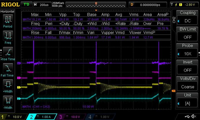
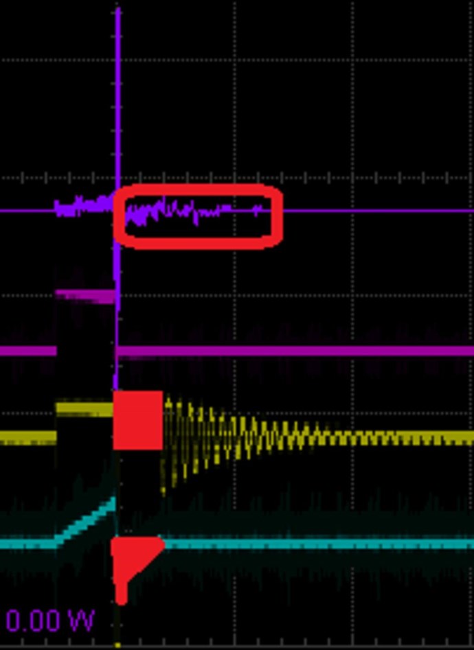
- Purple Trace is the Math, showing Positive and Negative Power.
- Pink Trace is the Gate Signal to the Mosfet.
- Yellow is the Input Voltage.
- Teal Trace is the Input Current, both Positive and Negative.
NOTE: 1 Volt x -1 Amp = -1 Watt, thus, average Input Power is reduced by a factor of magnitude, depending on how much: "One Partnered Output Coil Assisting your Input - This Coil brings down your Input Current."
Of course, I have spend many hours documenting these effects, sharing for all to learn from, if they wiosh, no one reads and replicate these effects as I have asked. Here is an example of Input Power dropping:
The Input Coil is used to tune your Partnered Output Coils into Magnetic Resonance. The closer to Magnetic Resonance you are, the more Input Current is sent back to your Input, remember the term: "REACTIVE AT RESONANCE" well, this is how it works!
Please understand, I have given Experiments showing all this already. Its in parts, not all at once 
Please take the time to read my pages, I have given ALL Answers already, its just the Understanding that's required!
Take steps to learn a little more your Electronics, as Switching is important, we have covered this here on this forum. Attention to detail, your output Circuit needs attention, it is wrong currently. Message left on your video!
Best Wishes,
Chris
- Liked by
-

-

-
-


Chris
posted this
12 October 2021
- Last edited 12 October 2021
Hi Fluktuacije,
Great work and Thank You for sharing!
I see you have several threads going, both similar:
We can help you! You are in the right place!
We have a thread: Builders Guide to Aboveunity Machines that contains all the information you need! However, in the mean time, the Exponential Curve you show:
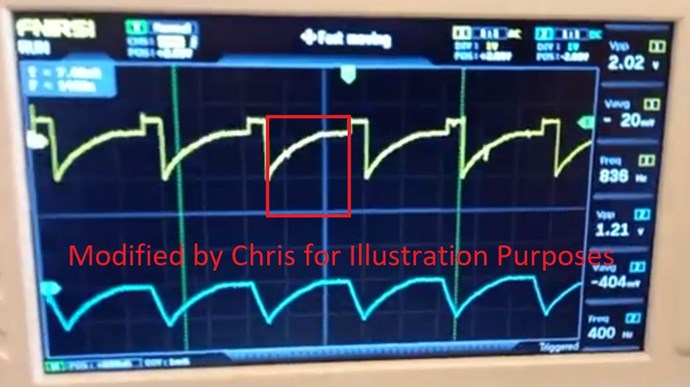
This is wrong because you have the Polarity of one or more, of the Coils incorrect! You should see a linear Sawtooth Waveform.
On the Input Side:
Now, what's going on here is the Coils Interactions are not correct. You need:
Each Coil has a job to do. Each Coil produces a series of Action Reaction Pairs.
The Actions are:
Action, Reaction and Counter-Reaction
So, the Input Coil Induces a Voltage on the Partnered Output Coil One, POne, POne then carry's a Current because it is Loaded. This is the Action, Input Coil, and the Reaction Secondary Coil.
The instant POne starts to Carry a Current, Partnered Output Coil Two, PTwo has an Induced Voltage because of this change in Current on POne, the Diode starts to Conduct and a Current Flows. This is the Counter-Reaction. The Current in PTwo must assist the Primary Current and also must Oppose POne.
The Arrangement is very simple, but it must be followed correctly to work, it does not make sense for many, but it works!
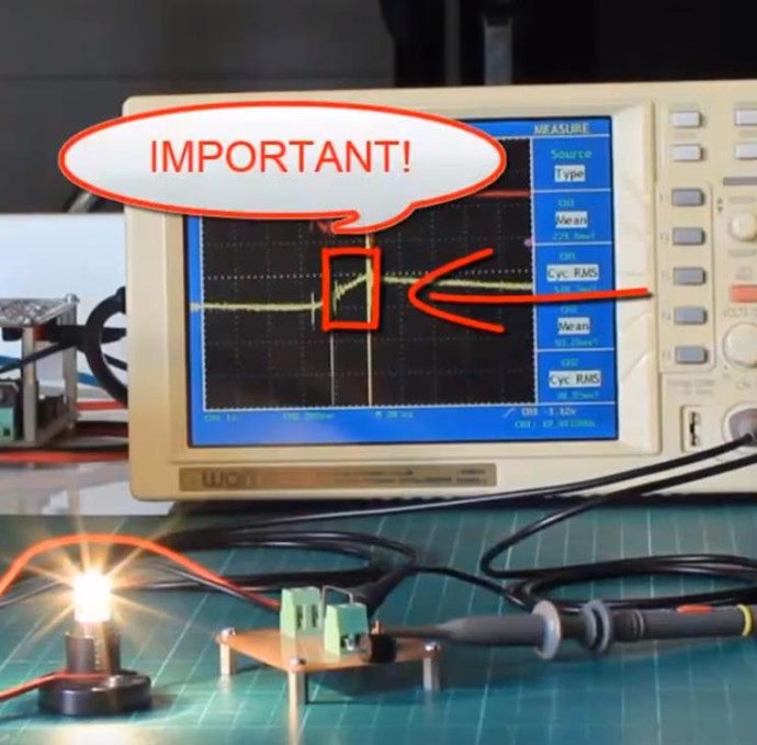
Now to make your machine go Above-Unity, you need to find Magnetic Resonance, and will need a larger core, larger Cross Sectional Area. The part marked Important, well, why is this important?
Its the area that the Partnered Output Coils is made to be Resonant, this 10% Duty Cycle is your Input and your Input gets your Coils into Resonance. This means you need to tune your input to get the best from your Partnered Output Coils. The best analogy here is: Rotor Speed on your "Generator", this speed is a requirement, and needs to be at a specific speed for the Output to be sufficient. Too slow, output drops right off, too fast, too much voltage is generated and the "Generator" will fail if it is beyond the ratings! The Input Coil is your "Generators" Rotor Speed. You need to get this part right!
Your Input becomes reactive at Resonance, meaning all your Input is returned to your Input Source, battery, PSU or what ever, Power is returned. I have shown this in the Thread: The Input Coil.
This is very easy, but one needs to be attentive, have great attention to detail and follow precisely, what is required to succeed! All who deviate fail, none succeeds if they do not follow instruction! All who Succeed have followed precisely the requirements! All who Succeed have said how easy this is!
Best Wishes,
Chris
P.S: Figuring out how to increase Output Voltage is Key! Its easy, so dont over think it!
- Liked by
-
-
-

Melendor
posted this
12 October 2021
Hello Fluktuacije,
Welcome to the forum.
Something is wrong with those waveforms...
I started the experiment 1 month ago and I have tried all combinations, but I never had those waveforms...
That mosfet switch you have....does it work corectly ?
Take the signal generator....the mosfet and the Bulb....and switch the bulb on and off with a Square.
Until what frequency the square wave remains Square? ...10 khz ...100 khz ?
If that works..disconnect the L3 completely.
If L1 and L2 are wound one above the other...same winding direction as you stated above ,
On the Triger (L1 coil ) ....You will have N on the left and S on the right.
On the L2 Coil You will have S on the left and N on the right.
Because you have placed a load on the L2 , Lenz Law is valid , and that is ""when a load is applied , the current in L2 will flow in such direction that will oppose the Coil that created it "
In this situation,you must place the diode on L2 , in such a way that it will allow the current to flow , in the proper direction of your new Transformer.
Use the right hand grip rule...and wrap your fingers in the direction of the winding....Your thumb will point out the direction of the Flux and the N pole.
It is not hard...You can do it.
I wish you good luck.
*Melendor the Wizard
- Liked by
-

-
-
Fluktuacije
posted this
26 October 2021
Hi guys!
I've managed to put in some time and here is what I've got if you would watch the video and comment...I forgot to say in the video: the frequency is 6kHz and 1% duty cycle, but the result is similar for a wide range of both of those values...
- Liked by
-
-

-
Fluktuacije
posted this
11 October 2021
OK thank you!
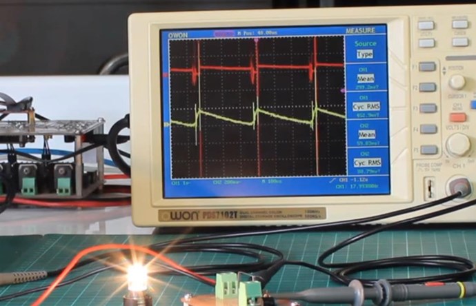
Here is the schematics:
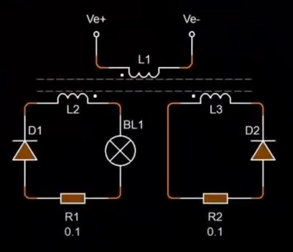
I am trying to achieve the triangular waveform at the output (bucking). The two coils are 250 turns and are wound CW/ CCW and the primary is wound in the same direction as the coil underneath (the thick red wire). Bulb is 10W 12V. The scope shots are at the 0.1 ohm resistors. I've tried flipping the coils, changing polarity of diodes but this seems the best I can get... how do I get over 1 ?
- Liked by
-
-

scalarpotential
posted this
11 October 2021
Ok I'll give it a shot.
First make sure the diodes are connected exactly the same as in the diagram, if they are both reversed, they function as a fly-back diode (very educational video
), don't try combinations yet.
Set the scope to DC coupling (top right shows ac for yellow and dc for blue), look it up. AC coupling removes the DC offset, that's why the yellow signal is around 0v instead of above (see arrows at the left).
Put the probe to the positive of a component and the reference to the low voltage, so the polarity of the signal is shown correctly, blue signal is negative voltage, reverse the probes and it's the sane as the yellow. signal, both are on poc1 so they must be the similar in shape.
You do seem have a slope after the pulse dutycycle (horizontal part), but it is exponential decay instead of linear (maybe because of distributed ccapacitance?). See what happens when you lower the dutycycle.
- Liked by
-
-
Fluktuacije
posted this
13 October 2021
Chris, Scalarpotential and Melendor thank you very much for your feedback! You have given me a lot if info and guidelines. This might be a slow thread so please be patient as I try to execute all of the given. Will reply with a new video as I go through your suggestions. Thank you again!
- Liked by
-
-
Melendor
posted this
26 October 2021
- Last edited 26 October 2021
Hello Fluktuacije.
This is a trip , a slow process ,
One of the reasons Chris , does not show a working device + schematic...is because people will hurry to replicate , and because they do not have a good understanding of what is going on , they will get hurt.
You have an Amps draw of 2.5 A at 1% duty ? .....
On the scope it seems that it is 99% ON and 1% OFF, or perhaps it is Inverted.
That AMCC core , you left aside , is 10 times better than your small ferite core.
You got the AMCC + wire + Bobbin ,
You have the stuff on your table , and you must clean your bench if you want results.
Take that AMCC core and build a transformer .
Wind L2 on the bobbin CW.
Wind L1 ( Trigger ) on TOP of L2, SAME winding direction. (10 Turns)
Place a diode and the bulb on the L2 and see if you got light.
Also you have DC Power Suply + Scope + Mosfet Switch.
In all these 3 devices , how many EARTH do you have ?
I have 100% faith that you can improve your setup , but you must clean your bench , and start small.
Take care of yourself and your equipment.
*Melendor the Wizard
- Liked by
-
-

Jagau
posted this
11 October 2021
- Last edited 11 October 2021
Hi Fluk
Several here are able to help you but to fully understand what you are doing and to know what goal you want to achieve I need to have a schematic to fully understand, And maybe we can help you.
Welcome in this forum and thank you for sharing.
Jagau
- Liked by
-
Jagau
posted this
11 October 2021
- Last edited 11 October 2021
Hi Fluk
Thank you for your feedback, I understand better now.
This diagram is from Chris he can surely help you, he knows very well this circuit.
Jagau
- Liked by
-
Fluktuacije
posted this
11 October 2021
- Last edited 12 October 2021
Thanms guys! I don't know what dc coupling is but I've put a probe across the bulb instead of poc2. Short new video:
- Liked by
-
scalarpotential
posted this
11 October 2021
Dobar dan,
Try DC coupling on yellow trace, diode puts current in one direction
You can see the voltage drop through the 0.1 ohm resistor to know the current, but you don't know the voltage drop through the light bulb and diode, try to show the voltage on those..

We're Light Years Ahead!

Our Above Unity Machines:
Recomended Protocol:
Members Online:
No one online at the moment
What is a Scalar:
In physics, scalars are physical quantities that are unaffected by changes to a vector space basis. Scalars are often accompanied by units of measurement, as in "10 cm". Examples of scalar quantities are mass, distance, charge, volume, time, speed, and the magnitude of physical vectors in general.
You need to forget the Non-Sense that some spout with out knowing the actual Definition of the word Scalar! Some people talk absolute Bull Sh*t!
The pressure P in the formula P = pgh, pgh is a scalar that tells you the amount of this squashing force per unit area in a fluid.
A Scalar, having both direction and magnitude, can be anything! The Magnetic Field, a Charge moving, yet some Numb Nuts think it means Magic Science!
Start Here:
Message from God:
Hello my children. This is Yahweh, the one true Lord. You have found creation's secret. Now share it peacefully with the world.
Ref: Message from God written inside the Human Genome
God be in my head, and in my thinking.
God be in my eyes, and in my looking.
God be in my mouth, and in my speaking.
Oh, God be in my heart, and in my understanding.
Your Support:
More than anything else, your contributions to this forum are most important! We are trying to actively get all visitors involved, but we do only have a few main contributors, which are very much appreciated! If you would like to see more pages with more detailed experiments and answers, perhaps a contribution of another type maybe possible:
They REFUSE to tell me why!
The content I am sharing is not only unique, but is changing the world as we know it! Please Support Us!
Thank You So Much!
Browse by Category:
Weeks High Earners:
-
Chris
310
-
Arya 100
-
 Gucio_81
92
Gucio_81
92
-
 FringeIdeas
90
FringeIdeas
90
-
---open-tesla-research.jpg?width=20&crop=0,0,20,20) akoteles
80
akoteles
80
-
thaelin 50
-
skywatcher 20
-
anarsu 20


The great Nikola Tesla:

Ere many generations pass, our machinery will be driven by a power obtainable at any point of the universe. This idea is not novel. Men have been led to it long ago by instinct or reason. It has been expressed in many ways, and in many places, in the history of old and new. We find it in the delightful myth of Antheus, who drives power from the earth; we find it among the subtle speculations of one of your splendid mathematicians, and in many hints and statements of thinkers of the present time. Throughout space there is energy. Is this energy static or kinetic? If static, our hopes are in vain; if kinetic - and this we know it is for certain - then it is a mere question of time when men will succeed in attaching their machinery to the very wheelwork of nature.
Experiments With Alternate Currents Of High Potential And High Frequency (February 1892).
