vita_cell
posted this
13 December 2020
- Last edited 13 December 2020
Hi Mitz
I tried it with a capacitor of the same capacity as a battery that I use and it lasts about 2 days.
A capacitor has no chemicals like a battery.
It is a passive component i.e. it cannot produce ions which produce the recharge of a battery by changing the chemical state of its electrodes. It cannot be discharge and charged at the same time with low voltage.
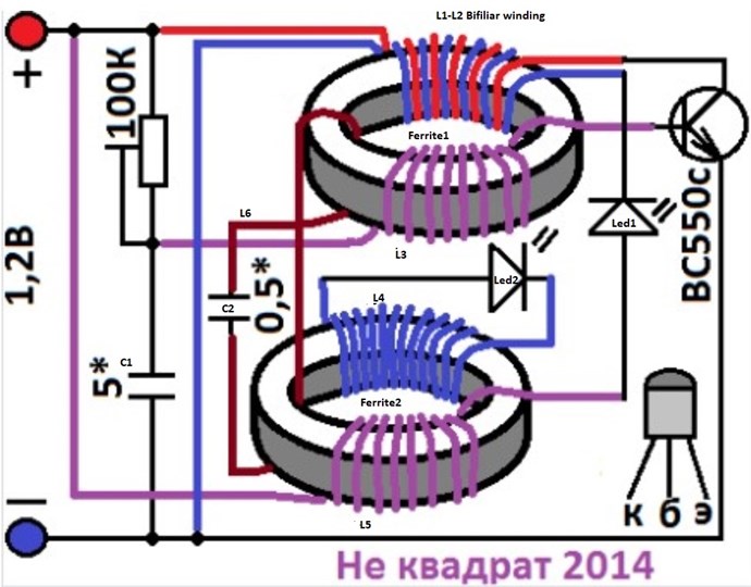
We can clearly see in Akula's schematics that he uses another process for recharging a capacitor at same time it is used. In his diagrams as I understand it, he uses the capacitor in a first phase, it is the discharge and in a second phase he recharges the capacitor. Thus we produce the charge and discharge in 2 phases
These are the type of experience that I am reproducing now.
Jagau
Jagau, hi, do you remember me? Hi again!! Will not write too much, but I have something to answer. As I born in USSR, I speak russian. Akula clearly says in one of his videos (from his Youtube's channel), that you should use high voltage capacitors, above 50v, he says that 63v are good enough, and those are made differently. He says, it is for catch high voltage peaks better (or something like that). Don't know if it true or not, but I must to say it.
Hope you success running Nekvadrat's circuit on some capacitor (or supercapacitor). I am not expert, but personally, I don't recommend you to use supercapacitors, because of vloss (leak). I have some good flashlights on 10000uF-25v (Jackcon), sharges instantly and works with good bright light for 5 minutes (well it lasts more but light dims) (no overunity or something like that). I did tests some caps of this type, and those aren't equal. Those from Jackcon have very low leackage, while some of NONAME/NOBRAND chinese capacitors of this capacitance have much more leakage while my Jackcon holds charge for days and has very small leaks. My experience with supercapacitors is, when you chare them until it draws no mA and disconnect them, you instantly will lose a lot of voltage. I recommend to testing with good brand capacitors, and well, if it higher voltage, the better.


 thay
thay

 Hi team! Nice work Baerndorfer! I have some little time this weekend to experiment a bit. I try the last circuit sketch by L0stf0x for the super cap. I don't know why... but again I have to reverse the coil on the base of the transistor. It is an interesting way to use POC. I will try this in other experiment to see the effect compared the way I usually connect them. Anyway I have not try on super cap but it works on 6 v lead acid battery! Thanks you and will love to see others experiment!


---open-tesla-research.jpg?width=20&crop=0,0,20,20)


