

Hello guys.
I will start this thread to document my progress with the Bucking Coils.
I want to say a big THANK YOU to Chris and Fighter for all the hard word and the advice's i received from them but nonetheless to all members that are experimenting here.
As Chris said...""Make it simple..do not over-complicate " ....well...DDS Signal Generator + Coils.
It is as simple as it gets.
Here are the pictures:


L1 (Trigger ) = 4 turns
L2 CW =16 turns
L3 CCW = 16 turns.
Square wave 5 V Peak to Peak.
At 1.54 MHZ I get a nice High Amplitude Sine wave on Both coils and a P to P voltage of 18 volts.
I have much thinner wire and I can get a lot more winds on that toroid,if this first step was good.
Will the same Bucking Coils procedure work with AIR CORE?...or it is a MUST to have a toroid,Iron core etc ?
Now,what will be step 2?....I want to light some LED's....Do you guys have a small Circuit I can try my BK Coil on?
I await your Thoughts Negative and Positive on my first BK Coil experiment.
Thank you very much and keep up the good work.
drago Bucking Coils Experiments
- 1.2K Views
- Last Post 13 January 2021
- Liked by
-

-

-
-


Hey Drago,
Nice work! Thank You for Sharing!
You have an Excellent example of Coil Symmetry there! Now all you need to do is aim for, and bring about, Asymmetry. Follow the Experiments I have shared here: Chris's Non-Inductive Coil Experiment
This link will also help: Builders Guide to Aboveunity Machines
In that link, I have given all the answers to get to the next step.
I do not recommend Air Core's, I have never recommended Air Cores, I have said in the past I have never had much luck with Air Cores. I find Air Cores far to Lossy and difficult to work with!
I wish others would stick to what I have shared and recommended, when things get changed, things don't work, there is a reason for everything I do. It is frustrating when others change things and it no longer works!
Good work and an excellent experiment to see the Symmetry between the two coils! Asymmetry now comes by following the link above, but remember, there are may roads that lead to Rome, many ways to achieve Above Unity!
Once you learn one method, you will see a world open up that is fantastic! One must follow the basic rules however, wandering off the path, will definitely lead to failure and frustration!
I was always taught: "Practice Makes Perfect", and Practicing, or Replication of others Successful Experiments, will quickly lead to, becoming an Expert in the Field! Learn as much as you can from My Work, Fighters work, CD's work, YoElMiCrO, Jagau and Vidura's work, and others here, as others here are very advanced! Way further ahead than others may think!
There is a little figuring things out, it takes a little work, but once you get to a certain stage, it very quickly becomes very easy!
Again: "Practice Makes Perfect", it is very true! Don't settle for one successful experiment that looks like others work, figure out exactly every aspect of the experiment! Look at every single detail with a thoroughness like never before, because learning the most simple thing, can be the greatest step forward, a path to understanding.
All here will help you where we can! Share your work and we can give you pointers and help, but if you don't follow the rules laid out, you must prepare for failure, like I have said. Success comes from understanding the basic rules, many here have succeeded! No other forum has ever shown this record!
Best wishes and again, Thank You for Sharing! Sorry for the long Ramble!
Chris
P.S: You now have the answer to what was said here:
Sweet used a center tapped coil, but never mentioned what he did with that center tap
- Liked by
-

-
-

Hello Chris and Guys.
Sorry for the late reply,but as in Chris Advice not to use air core,I have ordered some Ferrite Rods + 0.1 Ohm resistors.
It took a little bit time to deliver.
I have replicated Chris / CaptainLoz video 9 Circuit ..and the results....well...were not that good.
I am making a mistake somewhere,and any suggestions from you guys are very welcomed.
I just want to light 1 LED guys, nothing fancy....
L1 = Trigger coil 79.5 mm CW / 0.5 OHM Resistance
L2 = Output Coil 2 , 318 mm CCW / 0.7 OHM
L3 = Output Coil 1 , 318 mm CW / 0.7 OHM
1 mm Gage copper wire wraped on 15 cm Ferite core.
L1 is Wraped above L3
Picture with the circuit Below:

The Load ( LED ) has a full brightness at 3 V and 0.08 A (Power that none of my coils can deliver to it ) 
The Coils resonante bot at the same freq 1.661 Mhz and with an input from the DDS Signal generator of only 5 volts I get:
Peak to peak 38 V
If I ramp up the freq from 1.6 to 1.9 Mhz I get a very Dominant Sine wave from L2 ( Red Trace CCW output coil)
With 5 V square I get :
CCW Coil RED : P to P 91.36 V
AC RMS 32.19 V
CW Coil BLUE : P to P 32.77 V
AC RMS 10.24 V
I ramped up the Signal generator to its maximum to see what I get from the coils.
Instead of 5 V square ,I pushed 20 v Square and got the following results:
CCW Coil RED : P to P 346.8 V
AC RMS 122.2 V
CW Coil BLUE : P to P 122.7 V
AC RMS 38.18 V
I have set up the circuit on a breadboard like the picture below,and at 20 V square wave ,I got around 1 V in the LED.
The LED is barely bright.
Osciloscope waveform:
AC RMS : 4.26 V
P to P : 18.69 V
Freq : 421 Khz
I have also tried to switch the diodes,load ( + - ) and wires.
I have noticed that if I disconnect one wire from L3 the Secondary CW coil...the LED doubles in brightness and I get the following waveform:

P to P = 38 V
AC RMS = 8.7 V
I suspect that now with 1 wire pulled out,the circuit is open and we have STANDARD Electromagnetic Induction betwen the Trigger coil CW and the Output Coil CCW. ( Correct me if I am wrong),
Also,
Although the resonance of both coils are at around 1.6 and 1.9 Mhz, now,with diodes,resistors and Load I have noticed that the only Frequency I can make the LED turn on is at 430 khz.
As a beginner I did not expect a COP above 1...however with a Peak to peak of 347 V and a RMS of 122 V to get 1 V in the LED...I think I failed miserably.
Also my DDS signal Generator can max an Vpp square of 20 v and 200 mA.
I know it is not much..but it should handle 1 single LED.
Guys,sometimes I noticed something strange,and that is...at 50% duty cycle the LED was ok.....but as I lowered the duty cycle towards 20% the LED got a little bit brighter....Gues he liked more time OFF than ON.
OFFTOPIC:
Chris what is the best way to upload pictures on the forum?
I have noticed that you can not zoom on the standard pictured inserted with the Editor.
And there is a function ""Upload from external source""..how do we use that?..
Sorry for the long post guys,but I need your input.
I did as Chris said....""Keep it simple "".
Will continue to read on the forum and take a look again at LOZ and Chris videos.
Perhaps I did miss something.
Thank you everybody,you are doing a insane job.
Keep it up and stay safe !
- Liked by
-
-
-
-


Hi drago,
good that you start experimenting! In order to get the POC working, you need to have current flowing, a small led won't be enough, preferable use a filament bulb. Also the frequency should be lower, for most ferrites a few hundreds of khz is abolute maximum, usually much less should work better. You might need some switch, and external power supply to start.
I hope this helps some.
Vidura.
- Liked by
-

-
-
Hi Drago,
Thank You for Sharing!
An LED as a Load, is simply not suitable!
You need a Resistive Load, this means an Incandescent Light Bulb or similar. The Reason, you need a specific Current Flowing in the Partnered Output Coils, to make this work! This is important and covered in many threads on this forum!
You will need to match the load, use various different ratings. 3.6 watt, 5 watt and so on... Parallel them up as required.
It is the Current ( I ) through the Turns ( N ), that gives a Magnetic Field and if the Current is tiny, which it will be with a LED, then the Magnetic Field will also be Tiny! Tiny Energy will then be: "Generated" as a result. E.M.F = -n dPhi/dt.
By taking on this project, one has to be prepared to bite off a chunk of science that comes with this. One must follow ALL the guidance we have given, including the Loads we have used and shown.
Please see: Help with using the Forum for help uploading images.
I see Vidura has already answered with the same basic answer. Thank You Vidura!
Best Wishes,
Chris
- Liked by
-
-
Hello Guys.
It is weekend and is Experimenting time again.
After I read all week here on forum,
I have found a schematic from Fighter and I tried it out. ( picture below )
Also THANK YOU Chris and VIDURA for the tips.True,you guys use all Resistive loads,
I have bought 12 V 3W Car filament bulbs,and I tried to replicate the experiment that fighter Did,however the results were bad.


I tried to conenct the osciloscope as in the picture,but it is short circuit,if I connect the negative lead to the positive side of the mosfet / coil .
The output of the power suply was 12 v 0.2 A with the circuit same as I connect the bulb directly to DC power suply...12 V 0.2 A.
Am I missing something here?
Tks guys.
- Liked by
-
Hi Drago,
If you can share your work, then we may be able to help. Currently, questions as you have asked, are really non contextual, we have nothing to work from, we have no idea what you have done and where you are in the build.
Sharing Fighters work, replicated by a few here already, successfully, is not helpful.
Photos, Videos, Circuits, Scopeshots, all of this is required if you want us to help you!
You would have seen some very specific images in reading the thread which are better for Scope Connections:
Hey Fighter,
Excellent effort as always. Thank you.
Next time, when you get time, if you're able to supply the Voltage and Current measurements for that node:
Input:
Already done.
Output:
As you already know, measurements need to be Mean or Average, see here.
Chris
We have, in many places, posted about Scope Isolation. Ground loops must always be avoided. This can be done by running your Scope from a Battery Operated Inverter or similar device. With very careful planning, this is not required, e.g: If you follow the above Scope placements I have shared.
NOTE: Our Mosfet Switching is also Isolated, if yours is not, you will still have a problem. Meaning you may still need a Battery Operated Inverter or Similar device.
Another, full read of the thread: Romanian ZPM (Zero Point Module) really would beneficial, to understand the requirements!
Best wishes,
Chris
P.S: Quadratic Inductor Dimensions can be calculated here: Aboveunity.com Member Calculator you can thank YoElMiCrO for his Genius in figuring this relationship out.
- Liked by
-

-
-
Hello guys.
Chris thank you for the fast reply.
I wish my response time was as good as yours,but with a wife and small child it is very hard to find free time.
Before we start I want to say that I did not " SHARE " Fighter's work in a bad way with the intent of Copyright or something.
From the way you said it..it was like I am Sharing Fighter's work as My own..and that I did not DO.
I have already said above that ""The schematic from Fighter" .
Thank You.
Now ,my computer has blown up last week.My motherboard was completely fried...no rescue for her.
In the last 3 months of experiments,my Keyboard,mouse,and monitor were disconnecting all the time and freezing.
I think it has to do with the fact that my Oscilloscope and DDS function Generator are USB based and both are connected to the USB 2 port at the PC motherboard.
As you have 1000x times more knowledge as I do,you can make a small tutorial on the forum on " HOW not To blow things up ""
As all the devices in my house ( 100 % all ) ...have a common ground that runs to the base of the house,I can not find a solution how to isolate one ground from another. The Ground wire is the same for all the appliances.
Thank you.
For the circuit,
I have assembled the circuit and connected the probes as you told me. ""Keep it simple "" yes ?
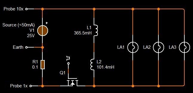
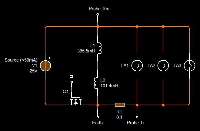
Here is the circuit and specifications.
Scope shot :
.
Blue 1x input and Red 10 x Between the 0.1 Ohm resistor and the load.
When blue is OFF the red makes the triangle wave and collapses slowly as you showed us over and over again. ( Hope I got it Wright )
Image with the circuit :.jpg?width=690&upscale=false)
..jpg?width=690&upscale=false)
Also,I and other people here do not and Can NOT compare ourselves with you,Fighter , CD, YoElMicr0.
If they have the ability to Read BETWEEN the lines when you post,well....sorry mate....I am not that advanced.
Please do not forget that there is no such thing as BAD Student...but only a BAD Teacher.
So please,throw us some bones mate..hard direct bones that we can digest on.
Thank you.
Much Love.
- Liked by
-
Hi Drago,
I appreciate you adding some images:
Immediately, I can see your Coils are not right. Fighter found a Quadratic Coil Configuration: See Here
In my current setup "L" coil has approx. 150 turns and "R" coil approx. 300 turns.
So, first, this needs to be realised.
Second, the Core Cross Sectional Area we have found to be important, when I say you need a bigger Core, please understand there are experiments on this Forum where we do use small Cores, so they do work, but one must realise, for Electromagnetic Induction, one of the main variables is Cross Sectional Area.

That's why we see Big Generators like this:


So, to achieve a replication, one must follow the original as close as possible, from Turns, to Wire Size, to Core Size, to frequency and Duty Cycle ( 25% Quadratic ).
With what you have already, you can replicate Wistiti's Work:
We will always try to help! Please understand we can only do this if you help us help you.
Many Members here are Geniuses! The rest are on their way! Learning has a steep curve! These Members and Readers in general that are learning, must follow closely what we share to be able to succeed.
Best Wishes,
Chris
- Liked by
-
-
-

Hi drago
Chris give you some great advice and one more if it could helps:
How not to blow up your oscilloscope or other devices connected to the grid
Jagau
- Liked by
-
-
-
-
@Jagau Thank you for the Video.I will watch it over and over again until I learn it.
.
@Chris thank you for the insight.I will continue to learn and continue the experiment in this thread,when I will have a biger core.
In the last 4 hours I have searched for information and seller for Amorphous Magnetic C Cores
in Europe from a reputable Seller as Hitachi.
I did not find any.
The sellers from Alibaba and aliespress are selling fakes,and they do not have the technology to cool the material down at
1 Million C as the big companies do. ( Else the molecular structure is the same as to a normal transformer )
In this situation we must find a way to make this work with other CORES that are world Wide available to purchase.
I will investigate the Wiswikii Circuit and I will build it,as I have the materials to do so.
I will post my results in his thread.
Until than,thank you very much for the support,and I hope things will run good for all of us.
Stay safe and be well friends.
Much love from Germany.
drago
- Liked by
-
-
-
Hi Drago,
We have a Category, on the right, under Categories: Amorphous Metal Core Suppliers, in there is a Thread: AMCC C Cores Suppliers, which we have contributed to to help Other Members.
Worth a read and if you have anything to add, feel free to post more Suppliers.
Best Wishes,
Chris
- Liked by
-
Hello lovely people.
I just want to make a little update to my thread,and tell you guys that I did not give up.
I am watching Chris,videos every day and read the forum every day so that when Santa comes,I will achieve the saw tooth waveform.
and guys,after centuries of waiting..in about 5 days, Santa will come.
Much love to you all, and keep experimenting guys .
Best regards,
@drago
- Liked by
-

-
-
-

Hello friends.
My core is here and I have already started the experiments.
My circuit is like @Chris's with:
L1 Trigger CW 0.66mH ; 0.7 Ohm ; 204 cm wire of 0.55 mm 1/4
L2 Output CW 17.5 mH ; 1.3 Ohm ; 816 cm wire of 0.55 mm
L3 Output CCW 18.5 mH ; 1.3 Ohm ; 816 cm wire of 0.55 mm
*The mH measure is that in the first 3,4 seconds after its starts dropping and dropping and dropping.
Here is a picture with the device and the circuit :

I have only a 2 channel usb based oscilloscope .I apologize.
The DC pulsed voltage is :
5.1 V 6 Khz at 0.10 A 20% duty cycle.
I can go higher in Trigger voltage but I get the "" Channel overcharge"" errors, and for the moment i just want to see if the saw tooth is there and looking for the effects as @ Chris has taught us.
Setting 1 :
Blue is the TRIGGER waveform VOLTAGE
Red is the TRIANGLE L3 output coil CURRENT

Setting 2:
L2 CW Current BLUE
L3 CCW Current RED
Same circuit,no modification..jpg?width=690&upscale=false)


On the circuit diagram I forgot to change the Inductor settings, so the 1 H on all 3 is wrong.
The inductance and resistance are written in the first lines of the post.
The triangle wave form is with the polarity of the diode in one way.
If I change the polarity the triangle wave goes away and the current goes x 3 higher at the power suply.
Should I change the Trigger with ticker wire ? Is the resistance too high on the coils?
What do you think guys?
I would love to hear your Input.
Much love.
@drago
- Liked by
-
-
-
Hey Drago,
A bit hard to tell, but I think the Partnered Output Coils Polarity is not right.
Worth checking your Coils oppose, using the Right hand Grip Rule and the Diodes are set according to this polarity.
When you have this working, you will have Three Energy Sources of Energy, only One Source you have to put in, which, most of it, you get back!
Thanks for Sharing! Great work! Good to see!
Best Wishes,
Chris
- Liked by
-
-
-
Hi drago
Just to help you you should never leave a mosfet gate without a reset resistor, add to 10k this will help you not to have false triggering of the mosfet, as you know a mosfet is activated above the voltage threshold with almost no current unlike a BJT transistor which needs some current on the base.
Read the pdf that I have provided below to help you understand the
Basic MOSFET gate drive circuit.
jagau
- Liked by
-
-


No one online at the moment
In physics, scalars are physical quantities that are unaffected by changes to a vector space basis. Scalars are often accompanied by units of measurement, as in "10 cm". Examples of scalar quantities are mass, distance, charge, volume, time, speed, and the magnitude of physical vectors in general.
You need to forget the Non-Sense that some spout with out knowing the actual Definition of the word Scalar! Some people talk absolute Bull Sh*t!
The pressure P in the formula P = pgh, pgh is a scalar that tells you the amount of this squashing force per unit area in a fluid.
A Scalar, having both direction and magnitude, can be anything! The Magnetic Field, a Charge moving, yet some Numb Nuts think it means Magic Science!
Hello my children. This is Yahweh, the one true Lord. You have found creation's secret. Now share it peacefully with the world.
Ref: Message from God written inside the Human Genome
God be in my head, and in my thinking.
God be in my eyes, and in my looking.
God be in my mouth, and in my speaking.
Oh, God be in my heart, and in my understanding.
More than anything else, your contributions to this forum are most important! We are trying to actively get all visitors involved, but we do only have a few main contributors, which are very much appreciated! If you would like to see more pages with more detailed experiments and answers, perhaps a contribution of another type maybe possible:
They REFUSE to tell me why!
The content I am sharing is not only unique, but is changing the world as we know it! Please Support Us!
Thank You So Much!
-
Chris
110
-
 FringeIdeas
22
FringeIdeas
22

Ere many generations pass, our machinery will be driven by a power obtainable at any point of the universe. This idea is not novel. Men have been led to it long ago by instinct or reason. It has been expressed in many ways, and in many places, in the history of old and new. We find it in the delightful myth of Antheus, who drives power from the earth; we find it among the subtle speculations of one of your splendid mathematicians, and in many hints and statements of thinkers of the present time. Throughout space there is energy. Is this energy static or kinetic? If static, our hopes are in vain; if kinetic - and this we know it is for certain - then it is a mere question of time when men will succeed in attaching their machinery to the very wheelwork of nature.
Experiments With Alternate Currents Of High Potential And High Frequency (February 1892).
