Demonstration: Standing waves and what they can do

  • 690 Views
  • Last Post 13 October 2021
Fighter posted this 10 October 2021

Hello,

Here is the simplest and the most clear demonstration of what standing waves can do when your device is designed and tuned for producing them and taking advantage of their power:


The demonstration is made by an researcher named Eleman from Greece.

This researcher have some interesting devices designed and built by him, he is selling some of them on Ebay in order to get funds for financing his research.

Also there is a website which provide some very interesting explanations about standing waves here:

https://davnxs.wixsite.com/teslatechexplained/page-1

For now the website is under construction, the builder is named David Monroe and he has a Facebook group here:

https://www.facebook.com/groups/therealteslagroup/

Keep in mind that when tuned our devices are also producing standing waves, I observed them on ZPM's output and also the partnered output coils are employing the same effect, they are producing high frequency equally and opposite magnetic fields.

Regards,

Fighter

Order By: Standard | Newest | Votes
Atti posted this 13 October 2021


Hi everyone.

I would just like to add a few thoughts to the debate. (it is not important to agree with him)


My starting point is this presentation theory: 

-If the same waves meet then what will be the change.
-Magnetic waves can only induce voltage.
- The direction of encounter of the waves also determines the excited voltage. Because there is a situation where it is just degrading the magnitude of the magnetic field. (more on this later in the video)
I would now demonstrate the magnetic fields (and thus the standing wave) excited by the current of the Poc1-Poc2 coils differently.
The two waves are provided by two H-bridge-controlled coils from two separate power supplies. We know the voltage triggers current to load. The current induces a magnetic field.
So. On a closed iron core, two identical windings des with windings in opposite directions. (200 -200 turns)
Same starting voltage for both power supplies.
Nearly the same starting frequency.
You can see what happens when the two magnetic fields meet.
It turns in the direction of one square and causes a change there.
The change as seen will turn either in the direction of one power supply or in the direction of the other power supply. (watch for amperes and former meters) seesaw. In the present case, the load is only a small influencing factor. But as we know from Chris’s suggestion, we need changes in the magnetic field caused by the load current. Respectively, its variable effects on each other.


Reflecting surface.
I have already shown these: 

On closer examination, the play of magnetic fields can also be observed here. (although this tends to push the reactive energy from one direction to the other. But there is also recharging towards the power supply and thus a reduction in current consumption) So we have to work to make the magnetic fields caused by the load make a profit.

I think so right now. I hope you understood the google translation somewhat.

Atti.

Chris posted this 10 October 2021

Hey Fighter,

Excellent Thread! I have tried to cover this in the Thread: Electromagnetic Waves

I would like to start by saying, there is a massive difference between the interpreted Standing Wave that some think as a Standing Wave. What do I mean? Well we are dealing with two Physical Properties:

  1. Voltage
  2. Current


Because we have two physical properties, we can have a standing wave of each, Voltage and also of Current, but not the same both at once. The reason is each is manifested differently!

Floyd Sweet made some important statements about this:


Now of course, the reference to a "Team Wave", is a Standing Wave! But there are two different manifestations, the second starting from the paragraph starting with "Similarly".


Voltage Standing Waves have nothing to do with the Magnetic Field, Voltage is already present.

In an Antenna, Standing Waves are well known to be damaging to the transmitted / receiving Signal:


The Feed Cable has standing waves all down the cable, but the Antenna's active element itself is in perfect resonance. If the Antenna's Active Element was not in perfect Resonance, and Standing waves were present, then the Antenna would not Transmit / Receive the signal. Floyd Sweeet said this very well also:

Resonance frequencies may be maintained quite constant at high power levels so long as the load remains constant. We are all familiar with AM and FM propagation, where in the case as AM, the voltage amplitude varies, and with FM, the frequency is modulated.

However, the output power sees a constant load impedance, that of the matched antenna system. If this changes, the input to the antenna is mismatched, and standing waves are generated resulting in a loss of power. The frequency is a forced response and remains constant. Power is lost and efficiency becomes less and less, depending on the degree of mismatch.

Ref: Floyd Sweet - Magnetic Resonance.


Now, Current, the Standing Wave associated with Current is somewhat different! We must have a Magnetic Field Cancellation for the Current Wave to Stand, this is not the case with Voltage!


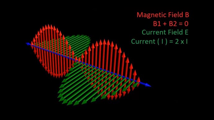
When we see this image, or a similar image:


We need to think of different things, and ask what might this be? Voltage or Current? Or both?

George's videos are excellent, please don't get me wrong, but I think we are all guilty of not being clear sometimes when we are learning. I know I have been guilty of this, I try my best, always, not to confuse others, but it happens.

George is using LCR Resonance and therefore Voltage Standing Waves, that's what the LED's are indicating, Capacitor Voltage, but at the same time, there is a Magnetic Component because of the Transformer, so there could be both Voltage and also Current Standing Waves present in this machine. Magnetic Resonance can not exist in this machine.

George's basic Circuit is:


I hope you don't mind me pointing this out, as it is very easy for people to get these differences confused.

Best Wishes,

   Chris

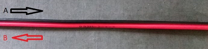
P.S: Also, we have Single Wire and also Dual Wire situations which are also different.

Fighter posted this 11 October 2021

Hi Chris,

Sure I don't mind.

I agree, current standing waves (implying opposing magnetic fields) are not the same with voltage standing waves.

In Eleman's video we see the amplification of voltage using voltage standing waves but seeing how LEDs behave we also can see what the magnetic standing waves effect can provide in the case of current. The result is the same: amplification.

I see it as a good demonstration for standing waves effect in general.

In this case the effect is employed for voltage but we can have the same effect employed for current too if we design our device to do the same thing using magnetic fields.

At least this is my current understanding about standing waves. But it's the first time I see the effect of standing waves shown by LEDs, we usually can see them on oscilloscope screens only.

Regards,

Fighter

Jagau posted this 11 October 2021

Sorry, no matter how hard I try to understand George's video, I can't see it, with a F.G. you can easily turn on the leds.


Remember that traveling waves are made up of forward waves and reflected waves. The standing waves are the degree of mismatch between 3 components the transmitter (source), the load and the cable which connects them.

We always refer to the power for the waves as well forward voltage divide by forward current equeal caracteristic impedance ( Ef/ If = Zo) and the current and the voltage must be in phase to have no standing wave.

It is the degree of mismatch that produces the standing wave producing a phase shift between the forward voltage and the forward current talking about power.

 In all of my radio communication systems it is the thing that I must avoid and that I check regularly in order to have a maximum of efficiency for my transmitters.

With a VSWR meter it is very easy to check this.

Jagau

Melendor posted this 10 October 2021

Hello ~Fighter
Thank you for the new Thread.

The person with the video ~Eleman from Greece , said he will post a schematic of the circuit soon.

He has an Isolation transformer and 2 capacitors for lowering down the resonant point...of the 2 coils.

There is a high probability that the has INPUT Paralel LC , which when resonating will have maximum resistance to the current flow , so the LED's will Dimm.

He shows the back of the board, but I can not see very well how he soldered the parts.

I will be very glad when he will post a schematic , and we will see that standing waves are involved.

* Melendor the wizard

Fighter posted this 10 October 2021

Hi Melendor,

There is the same schema (coil and capacitor) on both input and output sides.

I don't think that kind of LEDs require significant current, most likely it's not about the current but about voltage.

The fact that the input voltage is diminishing while the output voltage is going stronger shows what he shows in the secondary representation of the standing waves effect: less input, more output.

Yes, let's see if he will publish the schematic but from what I see there I'm convinced he is using the standing vawes effect, the LEDs on output are connected specifically to the nodes and antinodes on the output coil, taking advantage of the amplification effect of the standing waves.

I saw the same effect on ZPM's output where the voltage was stronger on specific points of the output wires, basically I had two identical light bulbs connected to the same output wires but one was illuminating stronger than the other depending on the points where they were connected on ZPM's output wires.

I was watching this guy for a long time, he is skilled in electronics and he's not in the research for disinformation, he works hard and experimenting a lot, I'm sure he knows very well what he got in his device.

I even bought one of his devices which is using a permanent magnet for gaining extra-energy and I'm gonna test it in multiple configurations including different LED light bulbs and with or without the permanent magnet:


So far his device in the initial video is the simplest and clearer demonstration I saw about the standing waves and how to employ their power in a device.

Regards,

Fighter

Fighter posted this 11 October 2021

Hi Jagau,

It's about the difference in voltage between input and output.

When the specific frequency is reached and standing waves appear the LEDs on output take advantage of the amplified voltage provided by standing waves. What LEDs show is the voltage on input is decreasing so much that the LEDs on input are off while the voltage on output is increased (by the standing waves) and the LEDs on output are illuminating while the LEDs on input are off.

Eleman is simply showing how to use the amplification power of standing waves (in this case amplification of voltage) while decreasing the voltage on input. My guess is the transformer's coils ratio is 1:1 (the simplest and most direct configuration for producing standing waves), considering this I think having an increased voltage on output while the input voltage is decreasing is a very nice demonstration of standing waves effect (in this case the standing waves are amplifying the voltage).

It's the equivalent representation with LEDs of the video Chris shown many times here with the two opposing water waves near the shore of the ocean generating a wave double in height after colliding.

Regards,

Fighter

Chris posted this 12 October 2021

Hey Guys,

Interesting debate! Yes, George's video is somewhat difficult to understand initially. I agree with Fighter that this is occurring:


Jagau is also correct, LCR Resonance specifies the Phase Shift to be up to 90 Degrees between Voltage and Current. This means we can have Voltage when there is no Current present and also Current when there is no Voltage present, but at a specific Time and a specific point in each Circuit.

The only time Voltage and also Current can be in Phase, is if the Inductor looses all of its Inductance! E.G: If the Core is Saturated.

I have some similar Transformers, some are 1:1 and some are not 1:1:


The one on the left is 1:1 but its clear, the one on the right is not.

If George has a Transformer that is not 1:1 then this is very easily explained, if it is  1:1 Transformer then yes Standing Waves are the only explanation here.

We must realise, every time there is Electromagnetic Induction, there is a Standing Wave present if one takes into account all the Fields. The degree of mismatch of the Phase of the Fields determines the Amplitude of the Standing Wave.

I have used the Image before:

The goal, this must be bought about, at the right time. Remember this is how Current is amplified:


This very same Parallel Wire Scenario applies here and also in every Electromagnetic System. Difference is, its Symmetrical, we primarily work in the Asymmetrical.

If we look at the Voltages and the Currents, and assume each Circuit has 90 Degrees difference between Voltage and Current then we get, on the Input: 


and we get on the Output:


Question is, each Current Changing in Time, creates the other Coils Voltage, so there is not much Phase Shift in there between Input Current and Output Voltage. The only Phase Shift will be Magnetising Current Delay Time and its normally very small!

Problem is, what does this relationship look like?

We know what the Capacitor / Inductor Voltage / Current Relationship is:

We will see a similar thing between Circuits, but Input Current, will be, almost in phase with Output Voltage instead.


Where:

  • Green is Input Voltage.
  • Orange is Input Current.
  • Yellow is Output Voltage.
  • Blue is Output Current.


I have given this a very small Magnetising Phase Shift, so there is not quite an exact 180 Degrees in there between Input Current and Output Voltage.

My Friends, please correct me if I am wrong! But my understanding is, at the moment, this is pretty close to what I believe will be occurring. Of course this only if the core is not saturated!

Best Wishes

   Chris

We're Light Years Ahead!
Members Online:

No one online at the moment


What is a Scalar:

In physics, scalars are physical quantities that are unaffected by changes to a vector space basis. Scalars are often accompanied by units of measurement, as in "10 cm". Examples of scalar quantities are mass, distance, charge, volume, time, speed, and the magnitude of physical vectors in general.

You need to forget the Non-Sense that some spout with out knowing the actual Definition of the word Scalar! Some people talk absolute Bull Sh*t!

The pressure P in the formula P = pgh, pgh is a scalar that tells you the amount of this squashing force per unit area in a fluid.

A Scalar, having both direction and magnitude, can be anything! The Magnetic Field, a Charge moving, yet some Numb Nuts think it means Magic Science!

Message from God:

Hello my children. This is Yahweh, the one true Lord. You have found creation's secret. Now share it peacefully with the world.

Ref: Message from God written inside the Human Genome

God be in my head, and in my thinking.

God be in my eyes, and in my looking.

God be in my mouth, and in my speaking.

Oh, God be in my heart, and in my understanding.

Your Support:

More than anything else, your contributions to this forum are most important! We are trying to actively get all visitors involved, but we do only have a few main contributors, which are very much appreciated! If you would like to see more pages with more detailed experiments and answers, perhaps a contribution of another type maybe possible:

PayPal De-Platformed me!

They REFUSE to tell me why!

We now use Wise!

Donate
Use E-Mail: Chris at aboveunity.com

The content I am sharing is not only unique, but is changing the world as we know it! Please Support Us!

Thank You So Much!

Weeks High Earners:
The great Nikola Tesla:

Ere many generations pass, our machinery will be driven by a power obtainable at any point of the universe. This idea is not novel. Men have been led to it long ago by instinct or reason. It has been expressed in many ways, and in many places, in the history of old and new. We find it in the delightful myth of Antheus, who drives power from the earth; we find it among the subtle speculations of one of your splendid mathematicians, and in many hints and statements of thinkers of the present time. Throughout space there is energy. Is this energy static or kinetic? If static, our hopes are in vain; if kinetic - and this we know it is for certain - then it is a mere question of time when men will succeed in attaching their machinery to the very wheelwork of nature.

Experiments With Alternate Currents Of High Potential And High Frequency (February 1892).

Close