Chris's Replication of Lari Man's Объект 013Б

  • Topic Is Sticky
  • 4.3K Views
  • Last Post yesterday
Chris posted this 16 October 2018

Hi my friends,

I have not replicated this one yet! So, I am making a dedicated thread for this replication. I am going to build the Lari Man's Lantern,, which was called the: Объект 013Б.

I copied his video and postings from realstrannick.com:


I have all the original files.


Another video, looks to be a Google Live Stream recording:


   Chris


Light Up the Darkness!

Order By: Standard | Newest | Votes
Chris posted this 16 October 2018

I started with Circuit copy and layout.

I noticed the immediate similarities to works before Lari Man, works of the originating device of Andrey Melnichenko, then Akula, Ruslan and so on...


I decided to prototype a proper PCB rather than a through hole board:


Some assembly now. You can see I do not have the Parallel Capacitor installed across the Input Coil.


I have sensing pins, for Scope Probe placement, handy for checking and tuning the operation of the Circuit.

   Chris

Chris posted this 16 October 2018

My Friends,

In the original Circuit:


Coils, an interesting setup on this circuit. If one follows the Paths, the two Coils, Input and Output Coils, are shorted to each other at On Time of the IC. A quick throw together Circuit looks something like the following:


Where:

  • Q1 is the Integrated Circuit: MC34063

Of course, the basic Circuit here is almost exactly the same as others we have seen from Akula and Ruslan:

   Chris

Chris posted this 16 October 2018

My Friends,

The Circuit Board is mostly finished:


Coils are next, and they, I hope will be as close as possible the sizes, or more importantly the Inductance required. Some fiddling will be required.

   Chris

Chris posted this 16 October 2018

My Friends,

I have wound that many coils in my time, I just find them a little tedious now. However, they are the most important component in all devices!

The Coils and the Interactions between them are where we have an Open Door for excess Electromagnetic Induction.

I did not have any Litz Wire the size shown in the original video, so I made some:


I believe 19 strands, (Verified after incorrect Count), if Wire from the Shaded Pole Motor Coil Wire. I have about seven meters of wire and can make more as needed. Its a shame to destroy a good working motor to salvage its wire, but its for a good cause.

   Chris

Chris posted this 16 October 2018

My Friends,

Symmetry is a key factor in Science, everything has Symmetry! Magnetic Fields are Symmetrical, the Inverse Square Law shows how the Magnetic Field is inversely proportional to the Distance from the originating Magnetic Field.

So, a study of the Coils and the Placement show Symmetry:


Two equal and even Halves, symmetrical, make a whole!

BUT, there is Asymmetry, there is Asymmetry because our Inductances of the Coils are very different! One Coil has very much more storage in it than the other. The Magnetic Fields at any one time must be Equal and Opposite if we apply Faradays Law of Electromagnetic Induction!

What we do have, is a very different Reaction Time, or Time Constant in the Coils!

I do not have a Ferrite Core lie is shown. However, I have a few others that are similar.


My personal preference is for the Round Core, or the Toroidal Core. The problem is that this core does appear to have a slightly bigger cross section. This means more Flux can be contained in the core, which is a good thing, but the Inductance will be different also from the original Device of Lari Man.

I will have more soon...

   Chris

Jagau posted this 16 October 2018

hi Chris
I take note of the liz wire very ingenious.
It is difficult to understand how C3 recharges after the kick strat of the battery?
Jagau

  • Liked by
  • Chris
  • Augenblick
Chris posted this 16 October 2018

Hey Jagau,

Thanks, salvaging parts  from old electronics is a skill I have learnt over the years,. Makes for cheaper experiments and some parts are very hard to get on the market also which is crazy.

It is difficult to understand how C3 recharges after the kick strat of the battery?

Good Question, lets look at the schematics:


C3, the Run Cap, 220uF, is charged via L2 and the Diode D1, half Wave Rectified.

I bet your sick of me saying this, but, Electromagnetic Induction between the two Coils L1 and L2, the Time rate of change of the Magnetic Field in proximity of the Coils, induces an E.M.F or Voltage.

This Voltage induced is determined by Faradays law of Induction: E.M.F = -N dΦ / dt

I know you know this already, this is for other readers that may not.

So, C3's Charge is a result of Induced E.M.F of L2. D1 is half Wave Rectifying the wave. When the Switch is Closed, the MC34063 and L1 with surrounding circuitry can be powered by C3.

NOTE: It is mentioned in the Video and in other replications, that a "Tuning" is required!

this coil will buildup in general it remains for me to collect fee to collect here this transformer and already try tune and so here I finished the installation


So, some work, some fiddling will be required to get the operation, or interactions of the Coils correct. It is Standing Wave interactions that give us excess Electrical Energy! If one can thing of the Magnetic Fields Slapping together like Waves on a Beach:


Under the right conditions, one can get more than twice the original wave Amplitude!

   Chris

  • Liked by
  • Augenblick
  • ISLab
Vidura posted this 16 October 2018

Hey Chris,

do you have some information about the required core material, what spec's are needed? would basically a EE core work, I ask because I have some hundreds of this from a abandoned led driver project, and have asked myself if they could be useful for an application like the flashlight. I see you use a power diode as D1 fast switching I guess.

  • Liked by
  • Chris
  • Augenblick
Chris posted this 16 October 2018

Hey Vidura,

I think any core is worth trying Vidura! So yes I would have to say yes.

Yes, the Diode D1 is a Fast Switching, a FMXG22 Diode, but I have thought about changing it. In the original video, the Diode D1 was an old DIAC, Silicon Bidirectional Trigger Diode by the looks of it:


I may be wrong, and Scope Shots are not entirely supportive of this.

Importantly, the Time Rate of Change of the Coil Interactions will be changed by an Ultra Fast Diode. So I may have made the wrong Choice here, which I did make allowances for, by also incorporating standard Diode Through Holes on the PCB:


You can see, marked in Green, I have two part placements.

   Chris


  • Liked by
  • Augenblick
  • ISLab
Jagau posted this 16 October 2018

Thank you Chris for your answer.
My question was rather on the side L1 for L2 it's ok
As we are in buck mode, there should be a diode in the pin2
and as  the pin 7 and 8 are connected through a transformer L1 and a capacitor in parallel,

no diode need so we have a pulsed AC,

it must be the very low impedance of L1-C2 at resonance that handles the maximum current of the resistance R2 sense current.

If you think about it, yes maybe it would work only if C2-L1 are in resonance.

Jagau

  • Liked by
  • Chris
  • Augenblick
Chris posted this 16 October 2018

Apologies Jagau,

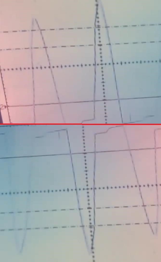
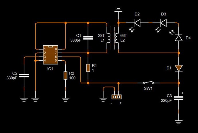
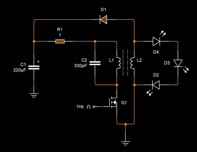
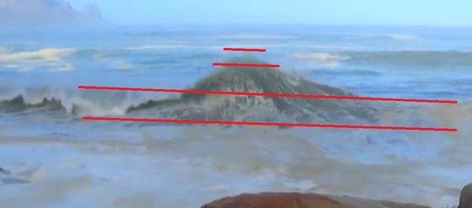
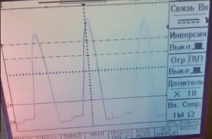
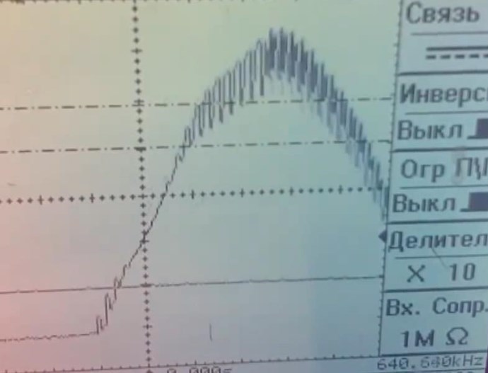
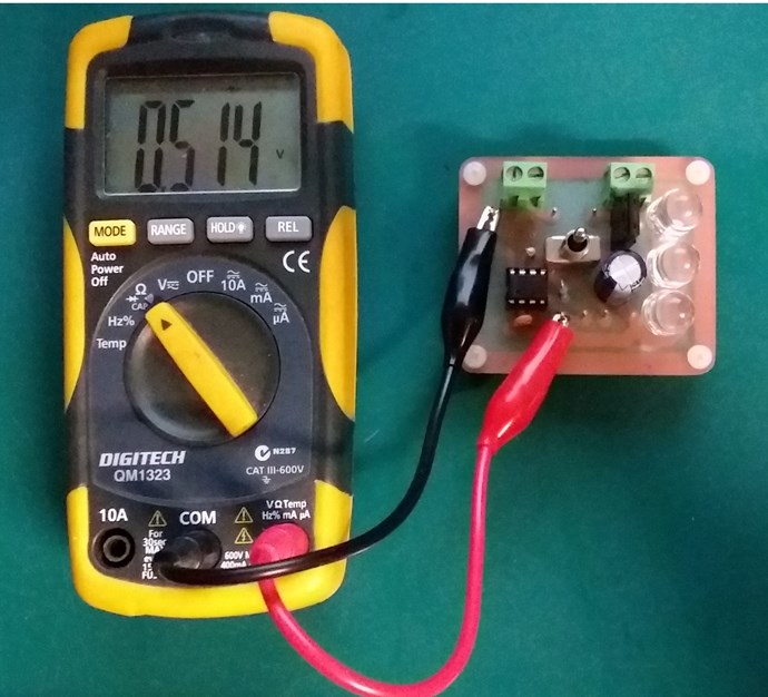
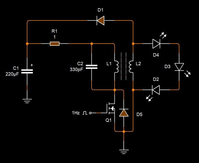
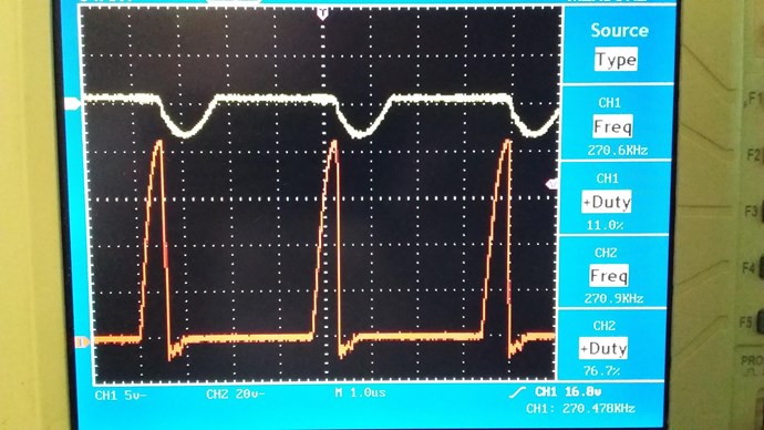
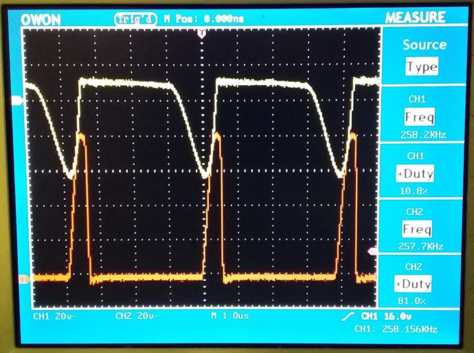
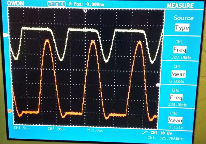
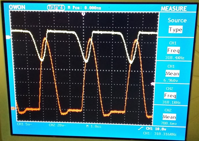
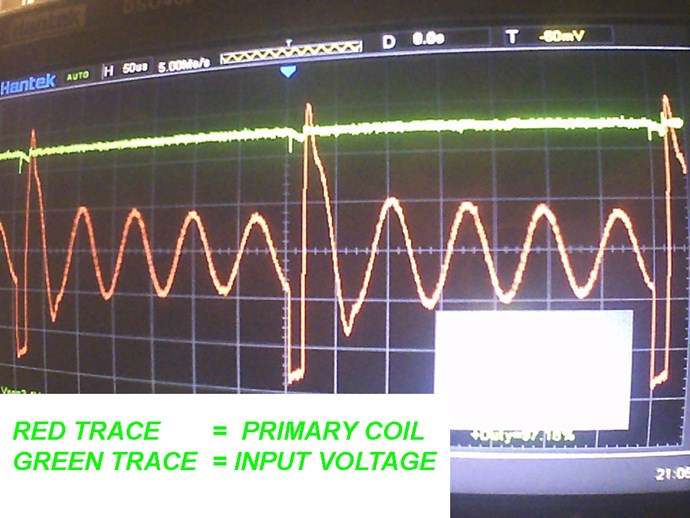
I thought I may have misunderstood your question. Yes there is a resonant Wave, or half wave seen on the Collector of the IC, Pins 1 and 8 connected to the Coil Cap Tank:


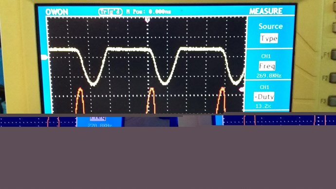
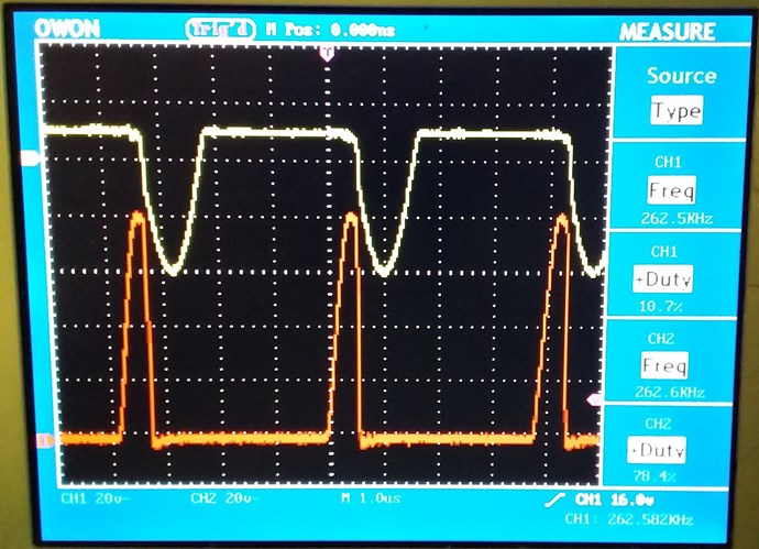
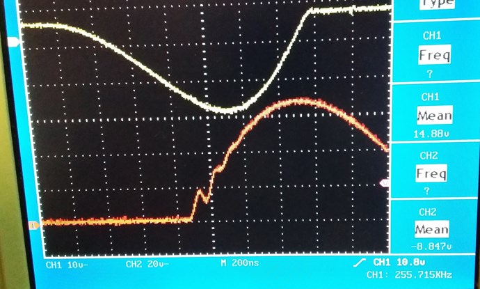
If we don't have resonance, we get a whole lot of decay Pulses after the main resonant Pulse, as you know. So something like the following:


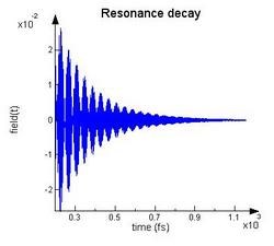
Likely off no use to others here, the Waves, if one takes one half, matched the other have that's missing:


So, one can see there is a Half + a Half, this making a whole AC Resonant Wave Form.

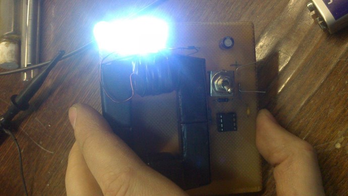
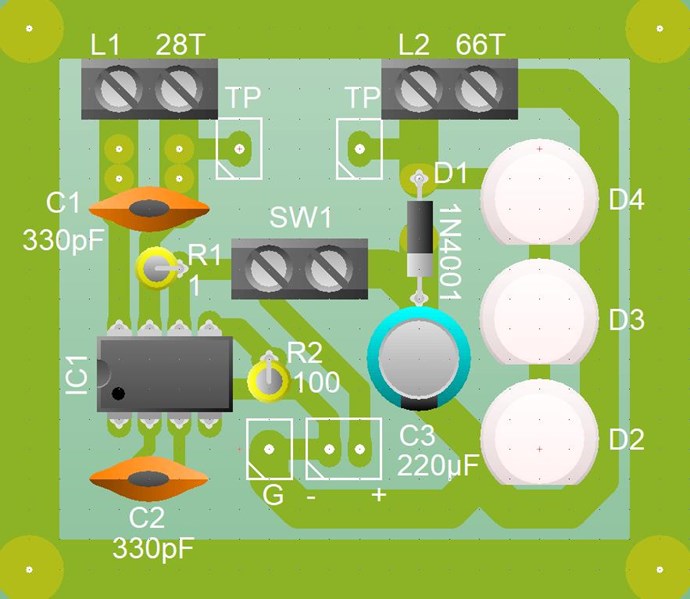
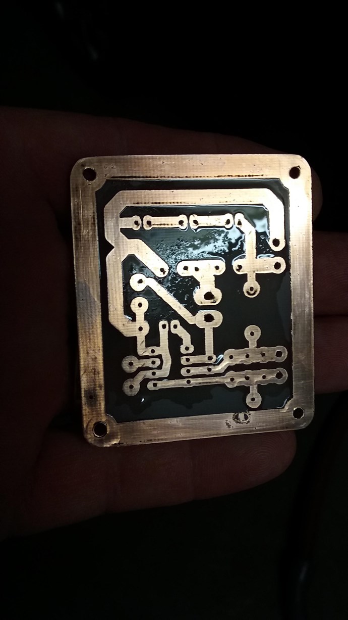
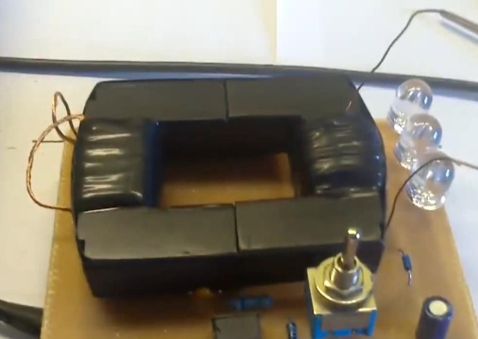
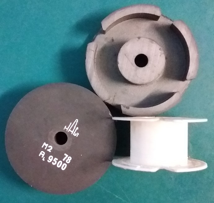
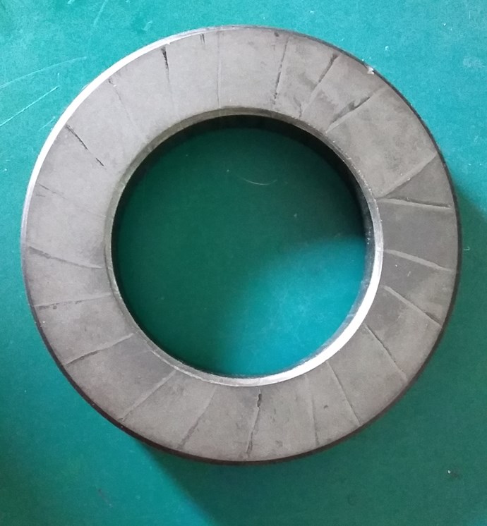
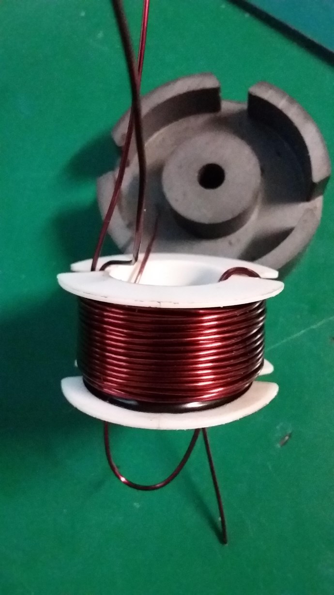
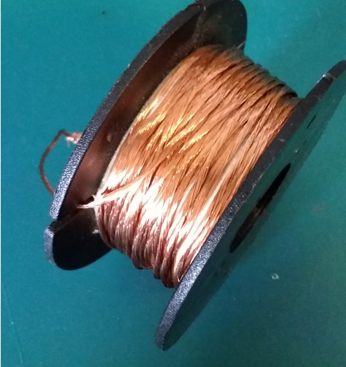
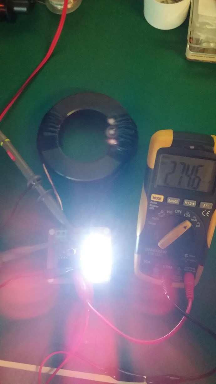
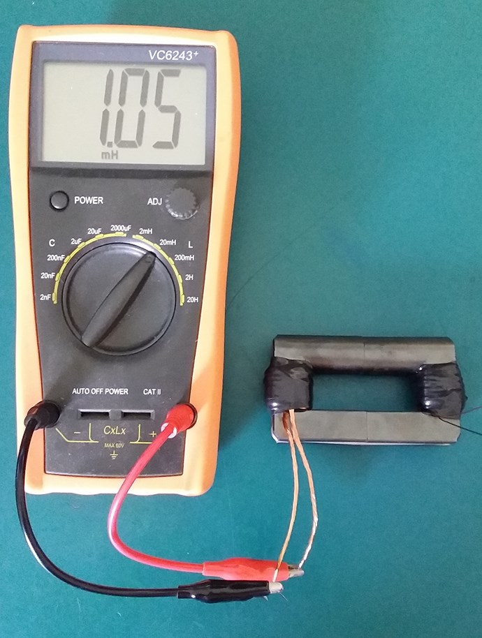
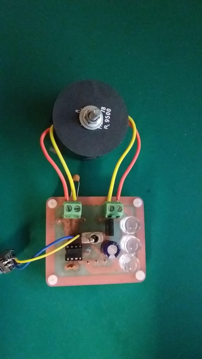
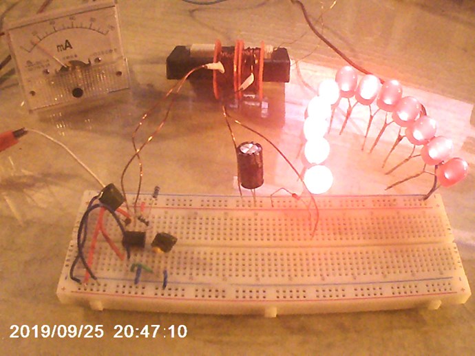
I have done some experiments already, used a few cores and seen this effect. It is of course not entirely like the above shot, when there is no resonance, but close. This is part of the Tuning in my opinion. This is interesting, because Lari Man had parts laid out, he had Circuit board built. It did appear as if prior Tests were done and the Coils and Components were known to work prior - This is how I would do it if I were to show a self runner!

It only makes sense.

However, this approach helps no one!

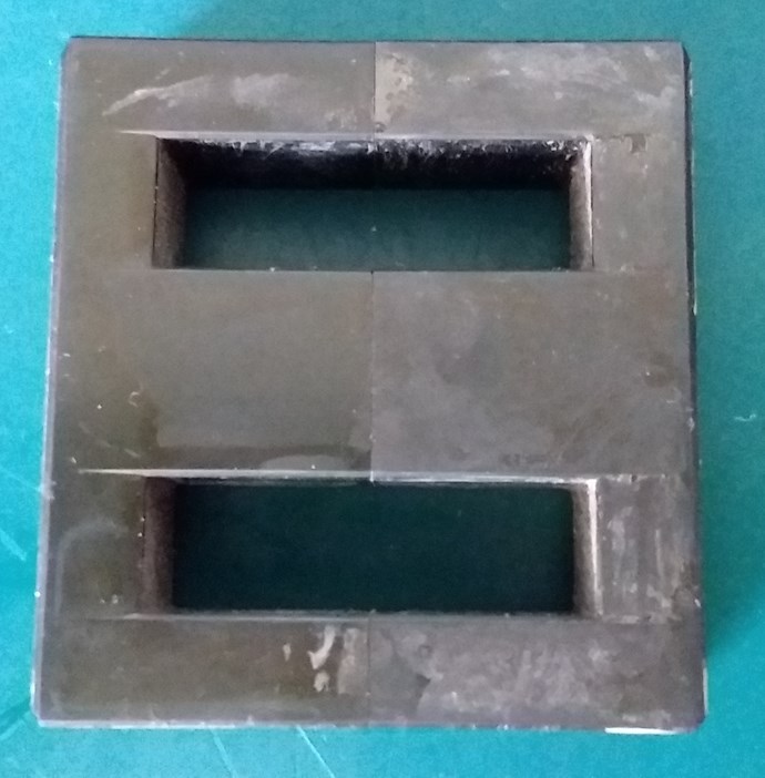
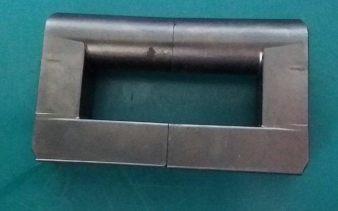
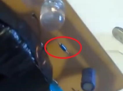
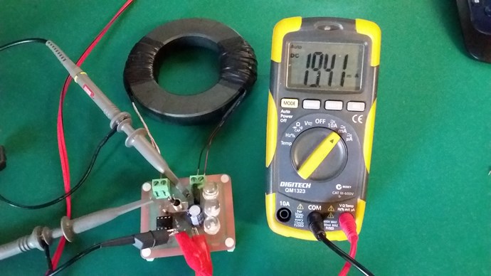
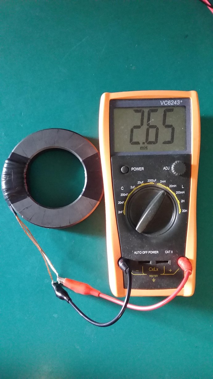
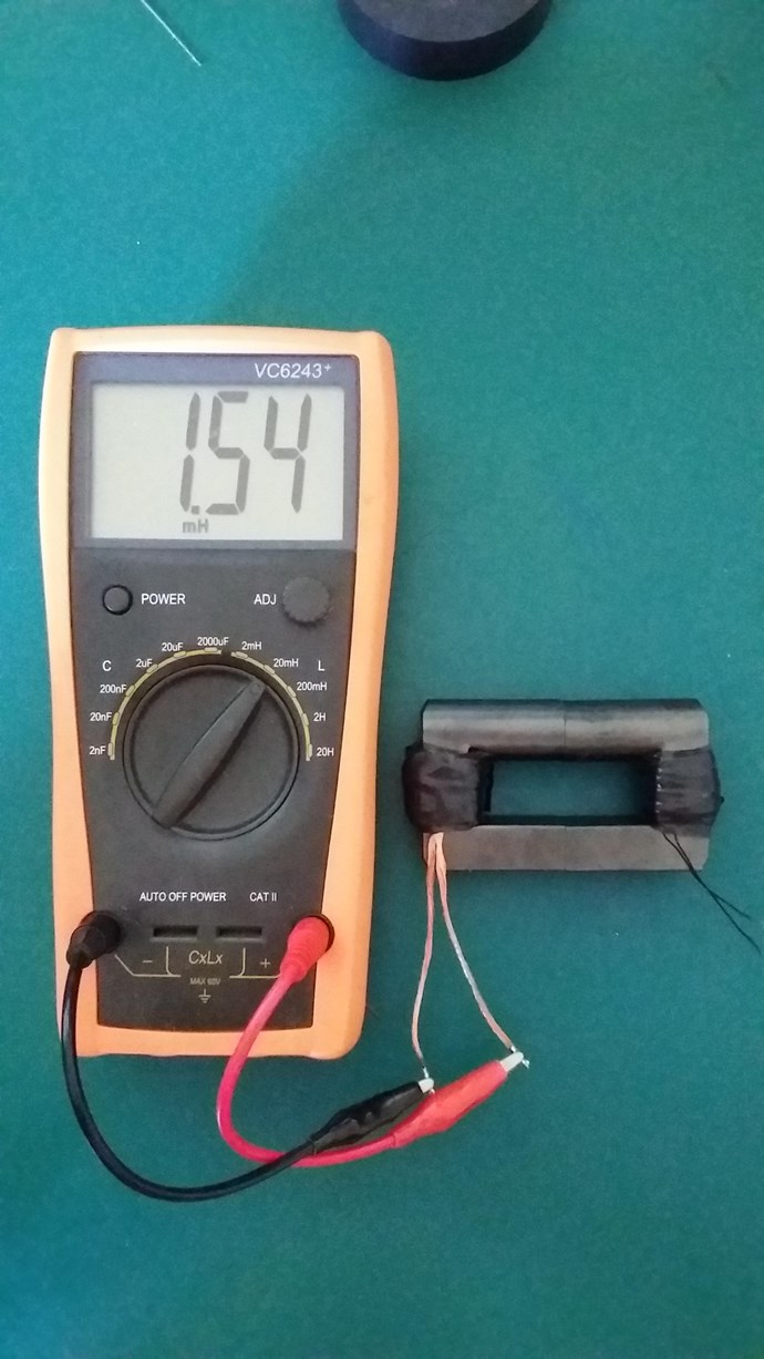
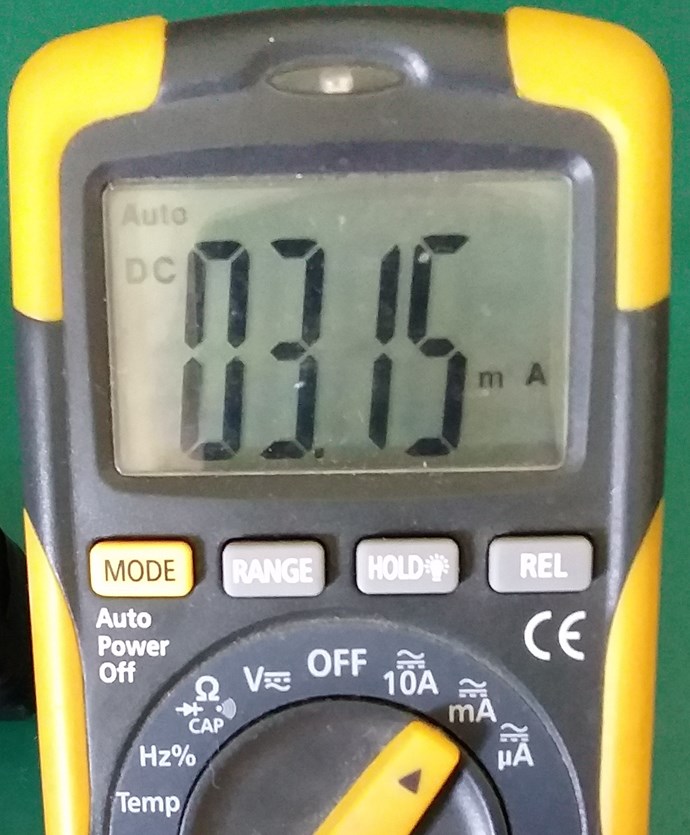
Now, I have not shown any Coils or scope shots, simply because I am way out of the ball park at the moment. Frequency was 230KHz, and I had no Peak Oscillations, and my L1 Parallel Capacitor was 2.5nf, way away from replicable results. My Coils are not currently sufficient to show anything of use.

So, all going well, some more results today.

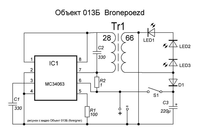
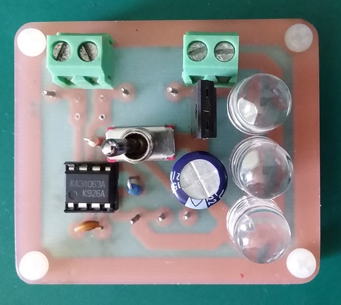
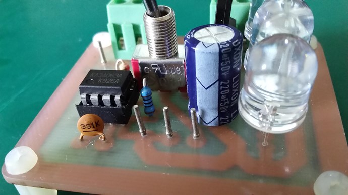
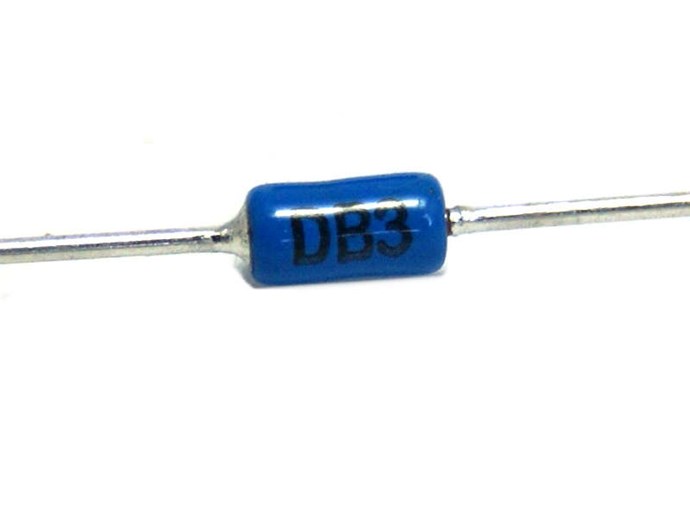
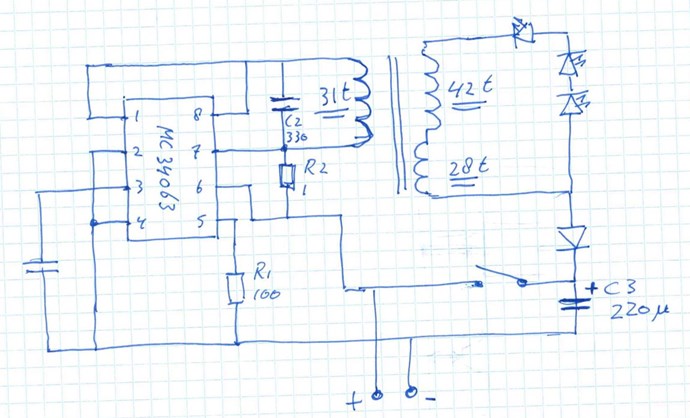
I also noted, what I thought were MC34063 IC Chips I had are actually KA34063, they have the same layout, but not what I want so I ordered some more, making sure they were what's required. Should be here soon!

   Chris

  • Liked by
  • Jagau
  • Augenblick
Vidura posted this 17 October 2018

Hi Chris ,

at the second look the circuit is somehow an odd thing! in the first video i see the skope is reading 650Khz  not Hz soC4 could be indeed 300pF, and the 250 kHz with your cap would be consistent, it seems that some kind of tuning (by which means?) is done when the ripple on the falling sine appears. The driving components of the IC pin8 are supplied true the coil, this could produce a kind of internal coupling. You could try a adjustable C4 to find the frequency for your coils?

Good luck!

Chris posted this 17 October 2018

Thanks Vidura!


As far as I can tell, the Base Resonant Frequency of LC Tank Circuit is around the 273KHz


I believe the Peak Oscillations are at 640KHz


I think the Squareness of the Pulses on top of the Peak Resonant Wave Form are the MC34063 Switching, which is very High Frequency for an IC that says its range is 100KHz!

On the scope we saw 5V per Division. So the Resonant Wave Peak is approximately: 36 volts

The Voltage on the Capacitor was measured at 10.83V


Also, three 3.5 Volt LED's in series are: 10.5 Volts. So this is correct and works out to be a logical Voltage on the output! This again is related to the number of turns.


We know a 10.83 Volt Pulse is not enough Voltage to be visible over and above the 36 Volts approximately!


So, I am going to say, being the Voltage is not Higher than the Resonant Tank Voltage, the Square Wave Cycles at the top of the wave are due to the Cyclic Switching In of the two Coils at Peak Voltage.

Effectively Bucking, or The Mr Preva Experiment situation where we see a Gain in Current, because Both Coils have to Interact together, at the same time to increase or amplify the Current.

Of course taking into account the previously noted similarity:


Where:

  • Q1 is the Integrated Circuit: MC34063


Would you guys agree given the facts laid out?

   Chris


Edit: it appears as the secondary Coil was disconnected at the time of these scope shots.

  • Liked by
  • Vidura
  • Augenblick
Jagau posted this 17 October 2018

Suggestion
Test a variable resistor of 1k instead of the fixed resistance of 100 ohms.
Can be a better control of core saturation

Jagau

  • Liked by
  • Chris
  • Augenblick
Chris posted this 17 October 2018

My Friends,

MC34063 Chip received and installed in place of the KA34063 Chip:


@Jagau, thanks for the recommendation, I will try soon if I don't see what I am expecting to see. My last post may be an interesting read for you?

Would like to know your thoughts!

   Chris

  • Liked by
  • Augenblick
Chris posted this 17 October 2018

My Friends,

A huge difference seen using the MC34063 IC compared to the previous KA34063. The MC34063AP is a MUST have for your Tool Kit!

I noticed many different results today:

  1. Completely different Frequency and Duty Cycle.
  2. Square Wave with no parallel Cap which I wasn't getting before!
  3. Parallel Capacitor Value in the schematic was much closer to resonance but not perfect!
  4. Chip getting warm and more current being drawn if external power is applied and no Output Coil is connected. Some noise in the Core. Input Current much higher, nearly 100ma, when Switch is off, the effects are not seen! Input drops right down,
  5. Nice writing on the IC, sorry had to put that in there tongue-out


Noting No# 4: This is why Lari Man had the switch off, he points to it and switches to off position:


Lari Man has the input power, on the shown points, no where near the output circuitry, after the Off Switch:


I wondered why he did this, now I know!

So, MC34063AP is a must have! My setup for this test, please remember, I am not showing any measurements or anything. This is just a test.


So all in all, a big step forward from yesterday! I had some MC34063 chips but must have used them all. This chip is much better than them also! Really nice feel to it!

   Chris


Vidura posted this 17 October 2018

Hey Chris,

yes i think the peakoscillations might be the high frequency, somtimes this IC's can perform a different mode of operation due to internal coupling, this kind of switching should not occur when the IC is controlled by a current sensing resistor, but it does, and the frequency is a good deal higher than specified in the datasheet.

In the schematic , I have noted :

when the switch is closed it is a non inductive coil(partially, for difference of turns), with the swith open it is a transformer( depending on the coils windings)

I think we almost got it, how this works!

Vidura

Jagau posted this 17 October 2018

Hi Chris


I used a voltage divider on pin 5 and this made a difference in IC consumption

no heat and voltage easily adjustable


Jagau

  • Liked by
  • Chris
  • Augenblick
Chris posted this 17 October 2018

Hey Jagau,

My circuit is around 9ma, a little more with a cap that's not quite in resonance: 12ma input.

I get 100ma when the switch is closed. Switch open, its really close to the Video of 5ma.

   Chris

  • Liked by
  • Wistiti
  • Augenblick
Jagau posted this 17 October 2018

Hi Chris
As I wait for other pieces for my other project
I will reproduce your experience on breadboard

if it does not bother you

Jagau

  • Liked by
  • Wistiti
  • Augenblick
Chris posted this 17 October 2018

Hey Vidura,

I agree! we are getting close.

If the wave form its self is anything to go by, I almost have it! Very close now! Fiddling is required and this is true with all these devices. something I have mentioned many times. A replication is not just a case of giving a few part numbers and build, there is always some Fiddling Required.

I have said a few times before:


Sorry, I had to put that in there!

Look at where we are today and where we were One Year ago! We are LIGHT YEARS Ahead of the other Forums! While they are still squabbling about petty things they were squabbling about 15 years ago!

This is all thanks to YOU! The Awesome Members here all working together! Learning and Achieving!

The reason I dedicated this Thread is to try to show the fiddling that is required wink

An example of some Coils I have tried:


In learning how a machine operates and where its sweet spots are, where machine resonances lay, Fiddling is required.

   Chris

Chris posted this 18 October 2018

My Friends,

A definitive way to test for a diode with out possible Chip Damage may be difficult. However, a Digital Multimeter I find a reasonable method for test.

Does the MC34063 AP Have an Internal Diode? It appears so:


From Pin 2, to Pin 8 and 1 there is a Voltage Drop being measured across the Internal Diode. This is the Conduction Voltage.

What does this mean? Well we must add to our Circuit, this Internal Diode. The Circuit will change somewhat in its appearance and how our Understanding of the Circuit works, perhaps for some anyway.


Where:


Of course, some will already know this, but for those that do not, it is something to think about!

   Chris

Chris posted this 18 October 2018

My Friends,

Please forgive me, I miss counted, on checking my original coil, there is 19 Strands. I have edited to correct the above error!

Thicker Wire at the same number of Turns gives a lower Inductance.

I have made some more Litz Wire, increasing the previously noted: 19 Strands, to 23 Strands:


Many years ago, I did a test on Resistance to Strands and the results were very interesting!


An Exponential Curve is seen. So adding only a few more Strands may make a lot of difference to the Coils Resistance, and also the Inductance.

My Frequency and Duty Cycle still need some work. Much better than what I had. I have a feeling I need to change the Timing Capacitor on Pin 5 from 330pf to 33pf or lower.

More results soon.

   Chris

Jagau posted this 19 October 2018

The gage is very important in the case of Liz wire
when we know how often our circuits operate.
A small PDF attached file attachment on liz wire.

Jagau

Attached Files

Chris posted this 19 October 2018


My Friends,

Some progress.


Device Changes:

  • C2 changed to a 33pf Ceramic Cap.
  • Input Voltage Variance test..


I currently have 28 Turns on the Input, with 23 Strands of Shaded Pole Motor wire currently measures:


I noted a few oddity's today:

  • I am at 2.7 Volts input, the Input is supposed to be 9 Volts.
  • The Input Voltage makes a big difference on how the Circuit Operates:
    • If I go up to 9 Volts Input, we get some oddities: at Switch ON LED's are on, at Switch OFF LED's are On. The LED's dim when Switch ON, and brighten at Switch OFF. This is in line with the video @ ( 8 : 10 ). This is while Input was connected.
    • At Switch OFF: Increasing the Voltage from 2.7V to 9V the operation of the circuit changes dramatically. At 6.1 Volts, we get a perfect sine wave at the Anode of the Diode. LED's sometimes flicker, but mostly are OFF. At other Voltages, the LED's are ON:
    • At Switch ON: LED's stay off from 2.7V up to 6.5 Volts, normal behaviour for Conducting Diodes.
    • Polarity of the Output Coil makes a massive difference. This will be covered below.
    • I am still not at Resonance, my Parallel Capacitor is currently a 330pF ( 331K ), you can see on my scope shots the On time and Off time are very different Duty Cycle wise.
  • My running Frequency is much closer to the video: 273KHz, around 270KHz depending on the Input Voltage! The Timing Capacitor at Pin 5, is better at 33pf., the Inductance of the Coil perhaps might be a little lower, or even Higher.


Output Coil Polarity:

A picture says a thousand words:


FIG: One


FIG Two


I am sorry the above images are not clearer, bad light. Anyway, there is a LOT of very interesting information one can gain here! Interesting stuff we have seen before in the Thread: Some Coils Buck and some Coils DONT.

Note: We are looking at Voltage Waveforms and not Current Waveforms.


Red Trace:

Input Coil, the Input Pulse, a half Sinusoidal Wave Form almost, is the Trigger Waveform.


Yellow Trace: 

The Yellow Trace is taken at the Diode's Anode, on the end of the Output Coil.

  • Fig One shows a Leading Pulse, before the Input Pulse in Time.
  • Fig Two shows a Lagging Pulse, after the Input Pulse in Time.

The wave forms on the Yellow Trace are quite different! But why, what's distorting the waveforms? Why would simply changing the polarity of the Coil make such a difference to the Timing of the Yellow Trace?

We should already know these answers. Of course, the Diode makes a difference in where the Coil will Conduct in Time.

I am not there yet, I have more fiddling to do, better my resonance, look to drop the input current by doing so!

   Chris

Wistiti posted this 19 October 2018

Wow! Excellent work my freind !!

  • Liked by
  • Chris
  • Augenblick
Jagau posted this 19 October 2018

Hi Chris
You advance very quickly, the goal is approaching.
I had planned to mount it on breadboard but after a first try a breadbord is too noisy.
I will mount it on a card the results will be more accurate.
Excellent results, we see in the last 2 photos the phase difference
thanks for sharing


Jagau

Vidura posted this 19 October 2018

Very interesting the results, I have noticed in some transformer experiments, that when the output is leading closely to the input similar distortion could be noted, Thanks for sharing.

Chris posted this 22 October 2018

My Friends,

I have been pretty close, but not quite there. Frequency close but not quite right, Duty Cycle was a long ways off. As a result, I was using a lot of Current.

After a lot of messing around with Coils and so on, I decided to move down to a smaller core. A little more in line with the original sized core of Lari Man's.

According to calculations, Inductance should be approximately: 1.03mH with a 330pF capacitor, for resonance frequency of approximately 273KHz.


28 Turns 30 Strands of Shaded Pole Motor Wire.


Now I have gone the other way, Duty Cycle much better, but Frequency a log ways off.

A small video Update:


So you can see, resonance brings the Input Current right down, I was using around 70 - 90mA with some experiments getting down to 30mA. Once resonance is found, 3.15 mA is a huge difference:


Lari Mas showed 5mA in Resonance:


Hope this is informative for all. More soon!

   Chris

Chris posted this 23 October 2018

My Friends,

With a little more fiddling, I have managed to get some slightly better results


23 Turns 30 Strands Shaded Pole Motor Wire.


Not yet self-running, but I am much happier with the wave forms! At switch on, Input Current does drop down, a little over 4mA at the moment. Might look to increase the Wire Gauge slightly on the Output Coil and also increase the Turns. 

More soon.

   Chris

Jagau posted this 23 October 2018

 I have a suggestion for your ferrite.
Melnichenko advises against using an iron clip to join the 2 ferrites
he was using tape (see his video)
and moreover it uses a very thin separator between the 2 ferrites (gap).
The 2 magnetic fields will not be of the same intensity, on the right it will be
much bigger with the melnichenko method.

Jagau

Chris posted this 25 October 2018

My Friends,

I mentioned in my last post about adding turns and using thicker wire.

The Charge Capacitor or Run Capacitor, we know must have a higher Voltage across it, than the applied Voltage to start the machine.

  1. 9 Volt Battery start Voltage.
  2. 10.87 Run Capacitor Voltage.


A short video to show, my Voltage is not sufficient to keep my Machine running:


Lari Man's video, showed the Voltage on the Run Cap was 10.87 Volts:


In the Video, you can see, @ Minute: 6:17 the Lantern is on, he then turns it off and then measures the Run Cap Voltage.


We are close, we have the Wave, we have the layout very close! I expect by adding a few turns of slightly thicker wire, I should get to the end goal.

   Chris

Chris posted this 25 October 2018

My Friends,

Two Winds:

  • 77 Turns 0.6mm wire
  • 100 Turns 0.6mm wire


Almost no Voltage increase seen, possibly the Core is saturated or the Core is too slow. Results not what I expected to see. More soon.

   Chris

  • Liked by
  • Jagau
  • Augenblick
Jagau posted this 25 October 2018

Hi CHRIS
I have used different configurations for this type of device and the only thing that works is

when I can control the saturation voltage of the system either by the input voltage or the voltage divider at pin 5
a precise adjustment of these two tensions made a difference.  Lets go, my friend your are on right way.

Jagau

Chris posted this 14 November 2018

My Friends,

I am still plugging away, not much to report. I have tried the Pot Core.

Results not much good. I have lost all the wave forms with this core.


   Chris

  • Liked by
  • Vidura
  • Augenblick
Vidura posted this 14 November 2018

Hey Chris, I found it very tricky with this designs to achieve the fundamental resonance also. Eventually I got a oscillations but a very distorted waveforms. There is a order of components on the way, when it arrives I 'll continue the experiments., good luck.pd have you tried to add the sheets?

  • Liked by
  • Augenblick
  • Chris
Chris posted this 14 November 2018

Hey Vidura,

These devices can be fiddly, some much more so. I have replicated several of the Melnichenko/Akula machines. A few years back I had some successes with a few and did not finish others.

Core is tricky, they are all different, all giving different results, sort of the point of me showing what I am.  wink

I guess, the point of this is to show that we should not give up too early.

   Chris

  • Liked by
  • Augenblick
  • ISLab
Chris posted this 28 November 2018

My Friends,

I am going to admit defeat on this device, time wise I have spent enough time. Many hours.

I do believe this device could work with enough time spent, I have to spend time in other areas now.

I may come back to this at a later stage.

   Chris

Vidura posted this 28 November 2018

Hey Chris, 

I was feeling similar with the last circuit of this kind, spent many hours testing, got nice waveshapes  and so but no energy gain at all,my white hair was changing to violet almostlaughing. so I leave it rest , waiting for more inspired moments. but anyway, a failed experiment can help learning something as well.

Chris posted this 28 November 2018

Hey Vidura,

Sometimes failures and sometimes successes, I can not always determine the outcome. Persistence is a key component.

   Chris

Jagau posted this 28 November 2018

hi friends


  Research is not easy, it is more difficult to ask the right question and in what way I should continue my research. I understand you very well, there are people who just read and brings little sense of research on the site, by chance there are researchers here that motivates me to continue my research and I am proud of to be part of it.

Jagau

Chris posted this 28 November 2018

Absolutely Jagau!

I have had some spectacular results with some of Akula and others.

This Technology does work, I gave up, this does not mean this Technology does not work, it means I could not get the right conditions in which the Bucking Fields could "Generate" enough energy for a self runner.

So please, I did not mean for a devalued result.

I have another device I plan to show soon.

   Chris


P.S: Yes I have failures too.

patrick1 posted this 25 September 2019

Hey Chris, - thought i would add my attempt too, - you did a great job getting your input down too 8ma, -   I personally was really impressed too get mine down too 14ma @ 15v, - but that is powering 12 oldschool low power LED's

if nothing else, its a very impressive circuit.

getreal156 posted this 30 September 2019

Hi Guys,

After reading through this post I noticed that most here have missed the most critical detail of this device.
The secondary is not 1 coil !
It is in fact 2 coils that are wound in opposite direction and connected in series. 

After unwinding 28 turns clock wise, he fiddles with a small piece of tape that holds the wire bend in place and then he continues with unwinding  41 turns counter clockwise (If I counted well). 
Take a very close look how he unwinds the coil in this video. He is trying disguise the winding scheme by turning and fiddeling with the ferrite core.

(starting at 25 : 35). 

The good news is that we have seen this type of winding many times before. I recognized the winding scheme from Earl Koenig and Andrey Melnichenko. Paul Raymond Jensen also describes the same type of winding scheme.
They are all doing exactly the same thing !

I bet Akula is using this winding scheme also

getreal156 posted this 30 September 2019

Hi guys,

Below the circuit were I have corrected the cheap trick of deception  
As this was already one of the topics that I was investigating, I'm going to burn some midnight oil on this also.

I think the 2 stage secondary might be a 'secret' that Melnichenko and others are trying to disguise.

Paul Raymond wrote that he needed another feedback coil to cancel the remaining secondary flux passing through the core.
I think the same principle applies here also.


Vidura posted this 30 September 2019

Hey GR, 

I think you are on spot with the secondary, seeing it as antenna. If we apply the formula suggested by YoElMiCrO it comes very close for a halfwave relationship:    (√0.5)∗41=28.9913780286484

Vidura

getreal156 posted this 30 September 2019

Hi Vidura, 

I read your post the other day about the formula I thought this was extremely interesting. Winding ratio's are critical and YoElMiCrO seem to be giving very valuable info. Unfortunately I'm not and EE and I have troubles with translating this formula into a practical coil ratio. I'm hesitant to ask and don't want waste any one's time, but maybe some one could post an example calculation to get me up to speed on how to apply this formula.

GR

Fighter posted this 30 September 2019

YoElMiCrO's coil ratio formula is easy to implement, the coil ratios could be: 0.25, 0.5 or 0.75.

If we consider N2 the number of turns for bigger coil and N1 the number of turns of the smaller coil we can have these coil ratios:

N1 = N2 * 0.25

or

N1 = N2 * 0.5

or

N1 = N2 * 0.75

So let's suppose you want your smaller coil to have 10 turns, so we have N1 = 10.

Then we have:

for 0.25 coil ratio: 10 = N2 * 0.25 so N2 = 10 / 0.25 = 40 turns for bigger coil

for 0.5 coil ratio: 10 = N2 * 0.5 so N2 = 10 / 0.5 = 20 turns for bigger coil

for 0.75 coil ratio: 10 = N2 * 0.75 so N2 = 10 / 0.75 = 13.3 turns for bigger coil

The thing you should start with is to choose how many turns your smaller coil should have (N1), then choose a coil ratio you want to go with (0.25 or 0.5 or 0.75) then you can calculate how many turns your bigger coil will have (N2).

getreal156 posted this 30 September 2019

Wow...What a forum.

Thanks so much Fighter !!! 
This really helps me out.

GR

Fighter posted this 30 September 2019

No problem, I'm glad I could help.

We're Light Years Ahead!
Members Online:
What is a Scalar:

In physics, scalars are physical quantities that are unaffected by changes to a vector space basis. Scalars are often accompanied by units of measurement, as in "10 cm". Examples of scalar quantities are mass, distance, charge, volume, time, speed, and the magnitude of physical vectors in general.

You need to forget the Non-Sense that some spout with out knowing the actual Definition of the word Scalar! Some people talk absolute Bull Sh*t!

The pressure P in the formula P = pgh, pgh is a scalar that tells you the amount of this squashing force per unit area in a fluid.

A Scalar, having both direction and magnitude, can be anything! The Magnetic Field, a Charge moving, yet some Numb Nuts think it means Magic Science!

Message from God:

Hello my children. This is Yahweh, the one true Lord. You have found creation's secret. Now share it peacefully with the world.

Ref: Message from God written inside the Human Genome

God be in my head, and in my thinking.

God be in my eyes, and in my looking.

God be in my mouth, and in my speaking.

Oh, God be in my heart, and in my understanding.

Your Support:

More than anything else, your contributions to this forum are most important! We are trying to actively get all visitors involved, but we do only have a few main contributors, which are very much appreciated! If you would like to see more pages with more detailed experiments and answers, perhaps a contribution of another type maybe possible:

PayPal De-Platformed me!

They REFUSE to tell me why!

We now use Wise!

Donate
Use E-Mail: Chris at aboveunity.com

The content I am sharing is not only unique, but is changing the world as we know it! Please Support Us!

Thank You So Much!

Weeks High Earners:
The great Nikola Tesla:

Ere many generations pass, our machinery will be driven by a power obtainable at any point of the universe. This idea is not novel. Men have been led to it long ago by instinct or reason. It has been expressed in many ways, and in many places, in the history of old and new. We find it in the delightful myth of Antheus, who drives power from the earth; we find it among the subtle speculations of one of your splendid mathematicians, and in many hints and statements of thinkers of the present time. Throughout space there is energy. Is this energy static or kinetic? If static, our hopes are in vain; if kinetic - and this we know it is for certain - then it is a mere question of time when men will succeed in attaching their machinery to the very wheelwork of nature.

Experiments With Alternate Currents Of High Potential And High Frequency (February 1892).

Close