

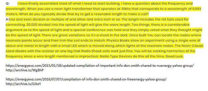
I am starting work on building a Smith Generator. Thanks to your work here, I am getting the role of Bucking Coils on the circuit. I found this link for starters, a pdf that purports to tell you how to build one:
projectavalon.net/forum4/attachment.php?attachmentid=25399
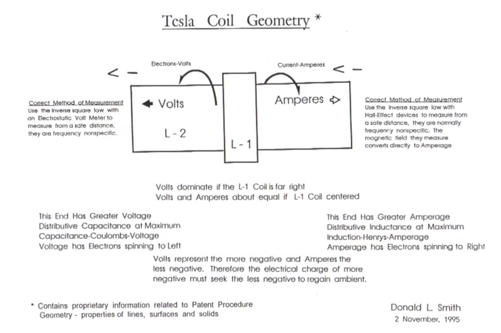
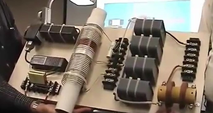
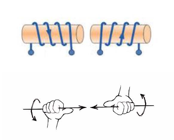
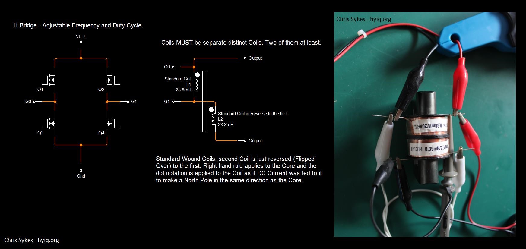
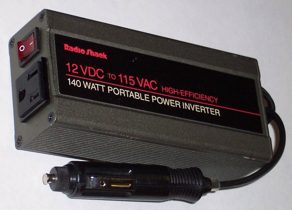
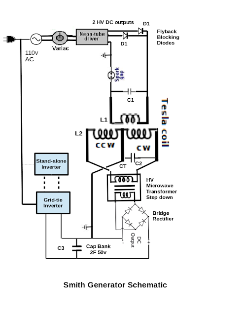
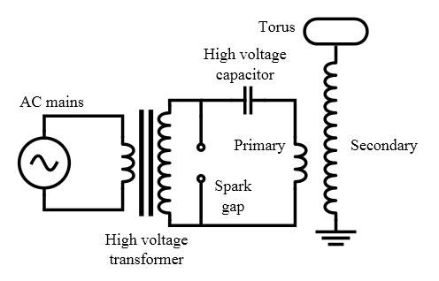
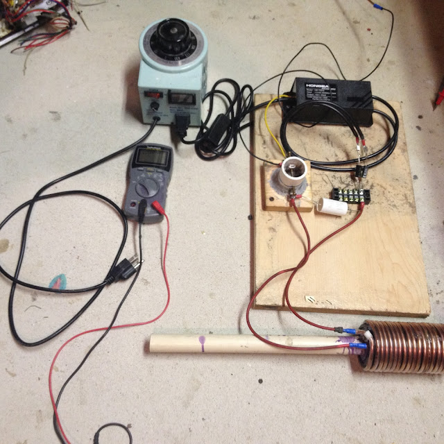
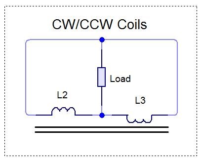
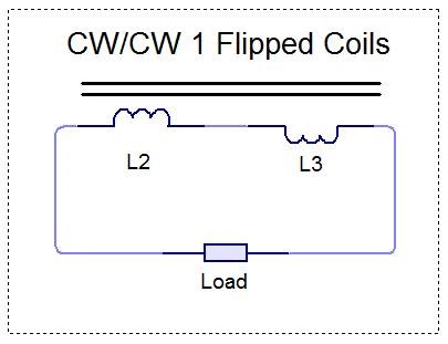
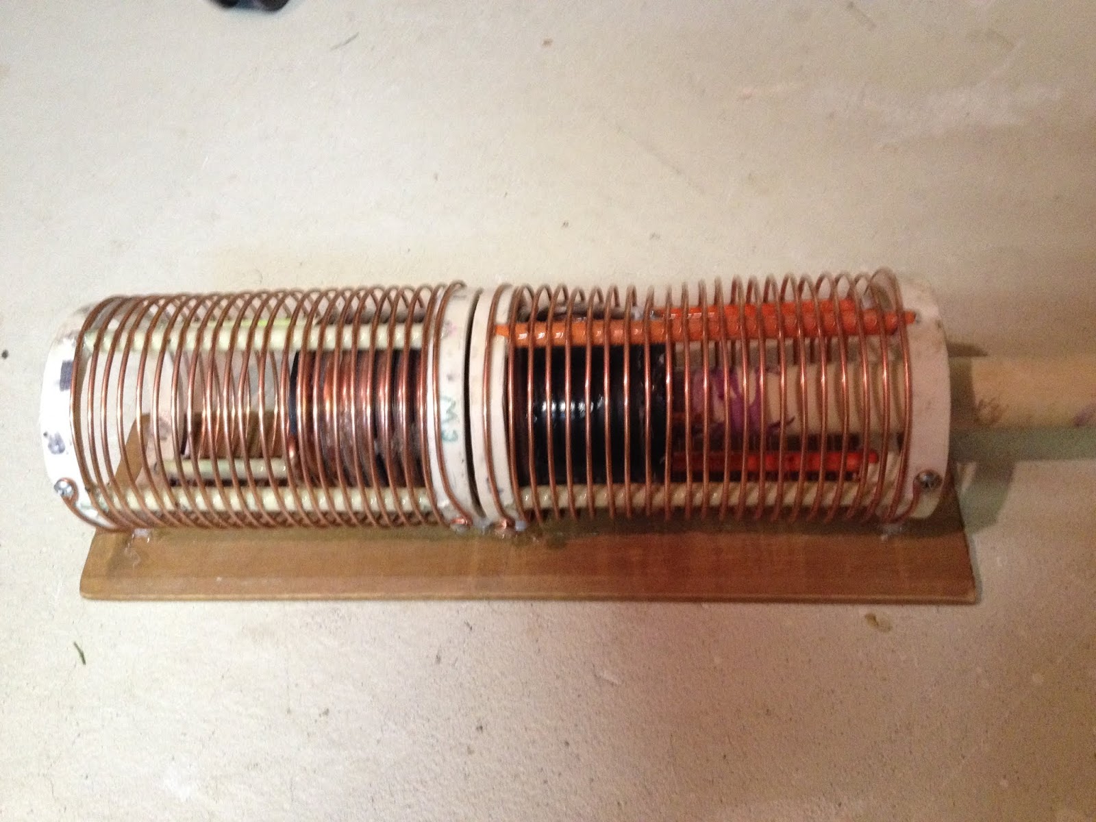
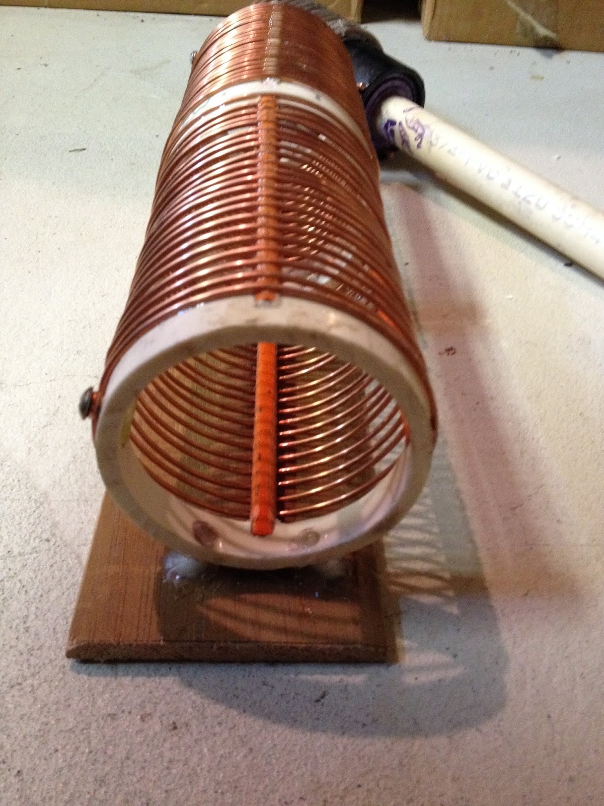
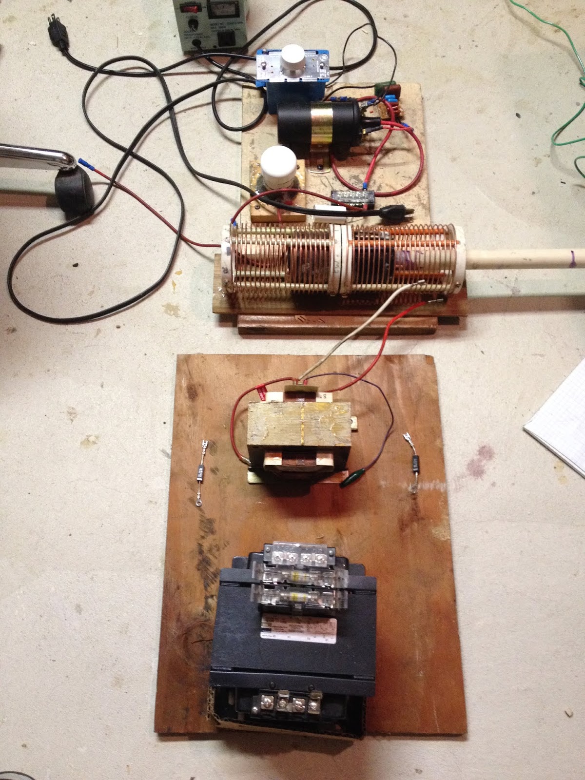
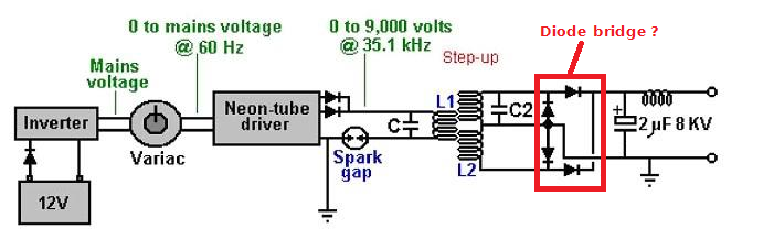
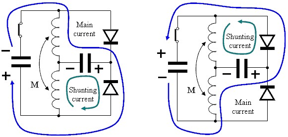
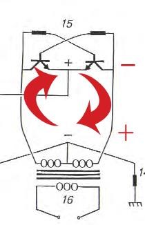
I extracted another schematic and made it an attachment below. What they do not mention anywhere in the document is that coil L2 most likely is a Bucking Coil, as you have most eloquently shown here! I guess they do say it is a "Tesla Coil". I guess that could be a Partnered Output Coil. I have seen similar schematics on youtubes by kdkinen, where he shows his replication attempts seemingly at least generating OU. His schematics I can clearly see the Partnered Output Coils. So with this understanding I think I will attempt a replication. It seems very simple. You use a 30 ma NST to get thousands of volts. The front of the the circuit as shown uses a small inverter driven by a 12v battery to get 120v AC, which is fed thru a variac to control the input voltage to the NST. The final output is supposed to be up to 8000v @ ~20A DC, as the L1/L2 is 4:1 step-up! Pretty astounding.
I am not going to use a battery to run an inverter to drive the system. I will just initially plug my variac into the wall. You do need a real sine wave input for this.
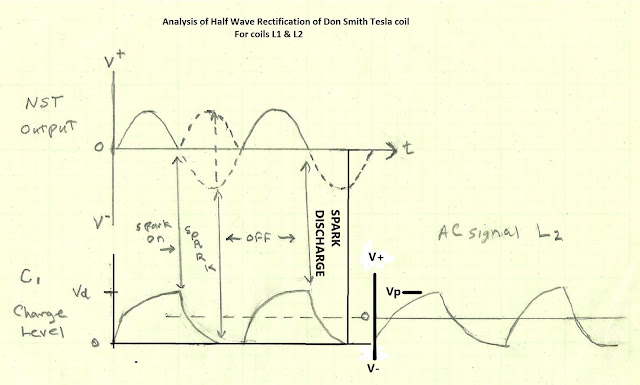
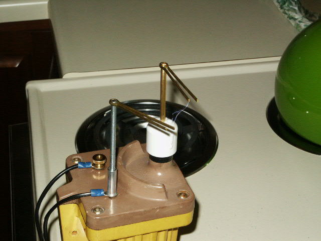
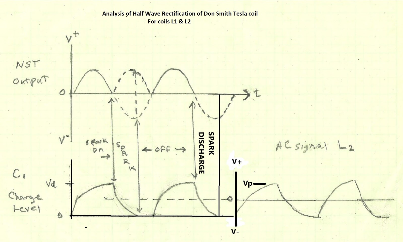
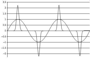
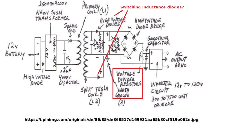
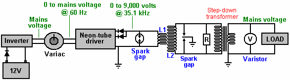
So the front of the circuit feeding L1 starting with the output of the NST is grounded at the center point tap of the NST. The output of the NST is rectified to extract the starting HV and then reconverted to AC with a spark gap tuned with resistors and caps to the coil L1 for about 31.5 kHZ AC .
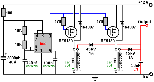
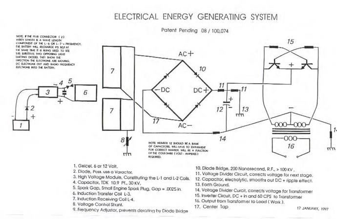
Here is a hand drawn schematic online and in the pdf : 
I got a little excited about solving the performance issues of the L1 circuit and clicked the solved button thinking it just applied to the post by Marathonman showing how Tesla built such circuits. But no, it got applied to the entire trhead, and is apparently a big database issue to correct. So please ignore the green solved check!


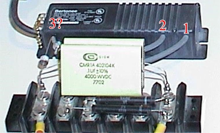
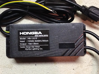
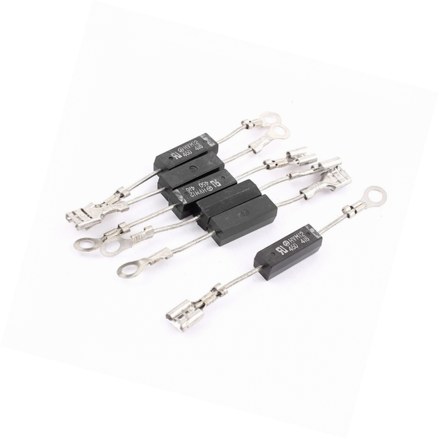
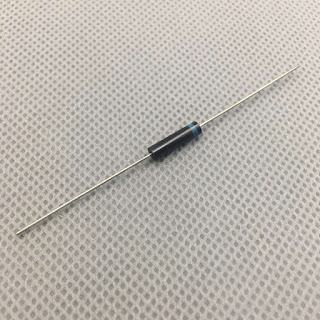
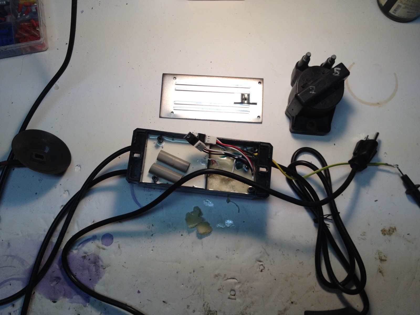
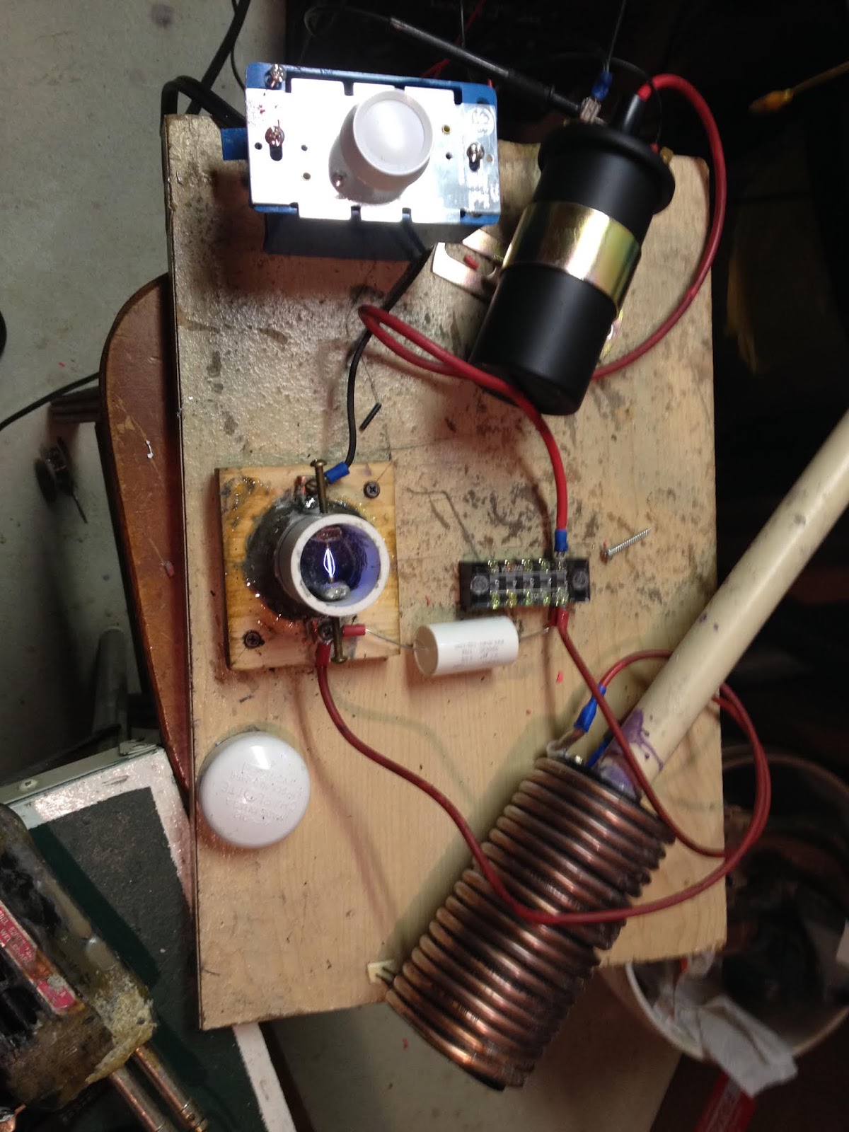
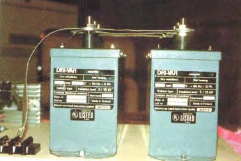
 I would like to focus on the Neon Tube Driver. In Don's instruction videos about building this system, he uses a model NST 12010. I believe it is a 120VAC input, 10KVDC output. I believe any Neon Sign Transformer NST) will work of similar specs. You could probably use a lower value, as the out-put of the step-up Tesla coil to the capacitor bank is 8KV. To avoid overdriving them, the variac must operate the NST at a fraction of the voltage. I have ordered an NST of the 10KV design, and it appears to have a rectified output already. I can't seem to find anywhere that they bother to explain it, assuming that we all know how exactly neon signs work, if we are buying a replacement ;-) If DC as I suspect, what are the pair of diodes doing on the output side? I think I heard in a Don Smith video or it may be in the Project Avalon document that they may be needed to catch and stop flyback voltages associated with the spark gap operation on the L1 coil. If anyone can confirm that the NST's output is DC, I would appreciate it.


 Your decision to share them is very much appreciated!


