Action, Reaction and Counter-Reaction

  • Topic Is Sticky
  • 2.5K Views
  • Last Post 18 November 2020
Chris posted this 31 December 2019

My Friends,

Some time ago, I shared the Complete Newtons Laws of Motion:

Why is Three the Magic Number? Action, Reaction and Counter-Reaction... Newton's Laws of Motion...

Ref: Partnered Output Coils - Free Energy - September 14, 2015


This takes Newton's Laws of Motion from a Symmetry only Law, to a Symmetry and also Asymmetry Law. A Law, now complete.

Tinman, aka Brad, also agreed with me on this fundamental observation:

Ref: Partnered Output Coils - Free Energy


The major question arises, why are Turns Important?

Well, its complex, and I am still learning, so please, what I have to say here is my opinion, with some evidence to support my ideas and works.

As I have pointed out: "ALL our Energy Machines to date are Symmetrical in Operation!" - They need not be!

Let me define again:

  1. Action - Input.
  2. Reaction - Output1.
  3. Counter-Reaction - Output2.


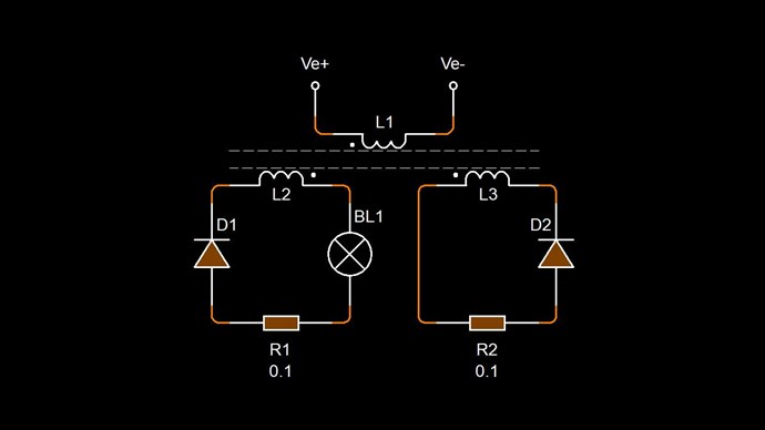
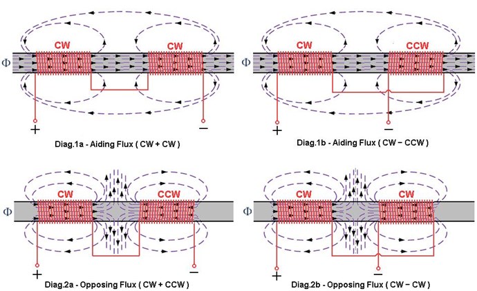
Where: Output1 Opposes the Input, Output2 Assists the Input. Total Output M.M.F is 1 where it is normally 0.


Too many Turns is Bad!

Why are too many turns Bad? Too many turns slows the Interactions between the Coils. Reactance, a topic I have covered in great detail in the past, videos on my YouTube channel, part of The Secret Revealed Series, explains the Actions of Magnetic Fields and how they can Act and React with each other.

We need a happy balance, where the Magnetic Fields can react together in a time frame that can make for a beneficial response in accordance to our input Timing. 


Not enough Turns is Bad!

Why are not enough Turns Bad? Similarly, as above, the Reactance, if it is too short, the whole process is over as soon as it is induced!

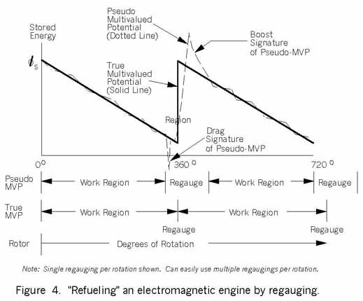
We gain Energy over Time!

So, the area under the curve is where we gain Energy, over the Time it takes for the Interactions to progress.

So we need a happy balance, just the right conditions for a maximizing of Electromagnetic Induction over a Time that we have identified.


Happy Balance

As with everything in life, everything is about Balance.

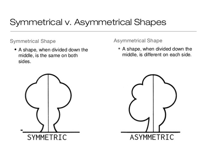
  • Symmetry is the Balance of Geometry!
  • Asymmetry is the Imbalance of Geometry!


We must learn where to apply and NOT apply the differentiation of Symmetry and Asymmetry! Like I pointed out yesterday:

"The Magic happens when you break Symmetry"


It is true! Top Scientists are now pointing this out! I like this guy! He is one smart cookie!

When we would normally desire a Symmetrical System, it is advantageous to investigate the reasons we do not investigate an Asymmetrical System!

Is the reason, we do not properly understand Asymmetry?

Richard Feynman pointed out, much of Nature is Symmetrical, but not all of it! Left and Right handed Physics concepts point out these concepts of one vs the other.

For decades we have been told about "Broken Symmetry"!


For decades we have had excellent examples, just some of the best ones I reference here.

We must ask the question: "Why is this inherently hard for us to grasp"?

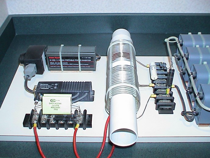
The Experiments I have shared with you all ( Chris's Non-Inductive Coil Experiment an implementation of How to build your own Above Unity Machine ), of which many are getting very good results, show that it need not be complicated!

Open your mind, look at the simple things, things that have been deliberately left out of Science, because they never wanted you to know about their tactic: Create Scarcity when there is none!

The MEG works, other machines work as was stated, Floyd Sweet, Don Smith, Paul Raymond Jensen and the many hundreds more I have shared with you for so long now!

Energy is not Scarce!

We are whirling through endless space, with and inconceivable speed, all around everything is spinning, everything is moving, everywhere there is energy.

Ref: Nikola Tesla


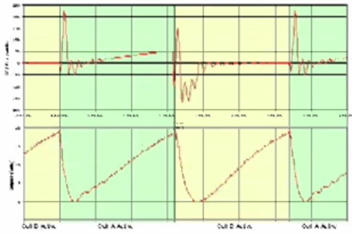
The Interaction and the Speed at which the Coils Interact determine the output of your Machine!

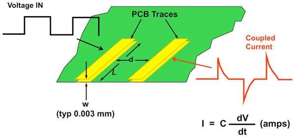
This is Current ( I ) and Time ( t ) between the Partnered Output Coils. The Cross Sectional Area ( CSA ), ability to hold more Magnetic Field, is also important! The Action ( Input ), Reaction ( POC1 ) and Counter-Reaction ( POC2 ), have timing events, you can control, that you can make for a greater output with often less Input. Meaning your Input goes down further as your Output goes Up!

Happy New Year my friends!

   Chris

Order By: Standard | Newest | Votes
Chris posted this 06 January 2020

My Friends,

I see possible confusion, I want to try to resolve this confusion, please let me know your thoughts! A Video to try and help:


I hope this clears up the processes we are investigating!

We can only do this together!

   Chris

Chris posted this 08 January 2020

Hey Loz,

Regarding your question:

What I'm still fuzzy on is how can Don's device work if both the secondary and the tertiary coils are wound in the same direction? Is it because the polarity is opposite? IE the ground is bottom of one and at the top of the other?


I have a series of experiments: Some Coils Buck and some Coils DONT, I go through and show the difference in Coil Combinations. Showing how the Coils can Act and Interact better in some configurations. It also shows that there is still Action and Reaction, but just not as much in some configurations. I also show the Sawtooth Waveform and explain it...

Of course, polarity is entirely dependent from where you start. If one swaps the Input Coil Polarity for example, the Output is also flipped. So its all relative.

Any and every change of Magnetic Field ( B ), which is, Current ( I ) through Turns ( N ), is Ampere Turns, and therefore M.M.F, in a System, can be a Source for another E.M.F to be "Generated". E.M.F is measured in Units of Volts ( V ), and M.M.F is measured in Units of Ampere-Turns ( NI ).

The direction of the Turns, can play a role as you can see in my experiments! However, most EE's will tell you that it makes no difference. I have of course shown this to be wrong!

Polarity does play a role, and we must realise, we are "Generating" DC, Our Output is not AC, its a DC, or at least mostly DC Output. I stated this many years ago, over on one of the other forums: 

October 01, 2015: 

@Brad;

A DC Current is possible to be generated from an Inductor. I am not going to explain how, or why but I have seen this several times. Mostly Flat DC Output. Maybe a small ripple on top of it. From what you say, I am guessing you already have seen this also.

No-one should limit themselves to any set boundary!!! Especially if the Boundary contains Unknowns!

Chris Sykes
hyiq.org

Ref: Partnered Output Coils - Free Energy


Of course, at the time I was not going to say about the Sawtooth waveform. It was not necessary what sort of waveform it was, just that it was mostly flat, a linear decrease in DC Current.

We have been misled! Physics  has not told the truth! Has not told the true story!

Much lays un-explored!

   Chris

Chris posted this 04 January 2020

My Friends,

The Magnetic Field, specifically the M.M.F, the Magnetomotive Force, is the only Force inside a Transformer or "Generator".

This Value of Force is the very basis for the formation of the Second Law of Thermodynamics. It is true, but ONLY in Symmetrical Systems! It does not apply directly, but does apply indirectly, in an Asymmetrical System:

Balance of Force:


In Each Cup, we Have M.M.F. In a Symmetrical System, the M.M.F is equal and Opposite! What does the Scale do? It sees Balance, each M.M.F has the same Force, or lets use the term Weight. Therefore the Scale shows us Balance! The Cups then sit at the same height and the cross bar sits level.

Remember: We are aiming for Asymmetry, we want to stay away from Symmetry, Broken Symmetry is the same as Asymmetry, there exists many names for Asymmetry, which is just the opposite of Symmetry.

Three is the Magic Number, it is the Asymmetrical application of Forces in a single System.

Every single Electrical System we have at our disposal is Symmetrical - Isn't that amazing!

Two Output Coils can be bought into a Resonant Action, where the change of one Coil is equal and opposite to the change in the other Coil. This is Magnetic Resonance! Our Scale sits Level, balanced, and the Input Coil that excites the operation, sees no load, there is an equal and opposite Force, from each Coil, one Negative and one Positive, this means as much Negative Force is exerted back on the Input, there is the same Positive Force is exerted back on the Input.

The Equation we have been through many times: 1 + -1 + 1 = 1, where in a Symmetrical System we see: 1 + -1 = 0.

We have a total gain in Energy, the M.M.F is not consumed as we would expect to see in a Symmetrical System!

This is important stuff, important to understand the Concepts for how these systems work.

We change the System to incorporate Asymmetry, Three Coils, Two Output Coils, M.M.F's balancing, 1 + -1 = 0, and our Input M.M.F then = 1, M.M.F that is not consumed! Our Scale is our Partnered Output Coils, the better the balance we get, by building a better System, the better our Energy Gain is! The Less Input we use, the more Output we get.

"The Magic happens when you break Symmetry"


It is true!


To Summarise:

Current through Turns is M.M.F. We must maximise each interaction, between each Coil. The Time Rate of Change of the Magnetic Field Creates a Voltage, the opposition of Magnetic Fields pumps Current! We must maximise the Time that these interactions can occur, and find the best possible frequency and Duty Cycle for these Magnetically Resonant Interactions to occur.

If we are smart enough to understand this post, then we are smart enough to build Above Unity Machines!

   Chris

Captainloz posted this 07 January 2020

Hi Chris,

Thanks for the new video.  You make some really good points, I’m glad you pointed out to just keep it simple, I’ve started to over think again....  There was a lot more I should have investigated before disassembling my successful experiment and using the core to make another experiment.  My new experiment has too many windings and is saturating the core causing too high of an amperage draw.  I’m thinking to go back to my original set up, it's just hard to disassemble everything after all the time I have in it…frown   I’m still a little confused regarding the MMF between the two output coils.  I thought we wanted to see a difference in the current between the output coils?  IE, the current difference we see between the two output coils is the current that is being pumped from the ether?  If the current is equal how is anything being pumped?   You said the 3rd coil (or tertiary coil) must assist the input coil.  I’m having a little trouble understanding this exactly.  Are you saying the 3rd coil is assisting the input coil it in terms of the MMF it has already received from the input coil? IE, the MMF received (during re-gauging period) in the 3rd coil is “assisting" only when the input coil is "turned off"? So the “assisting” is the opposing MMF of the 3rd coil acting against the other partnered output coil?     I hope my questions are making sense...    Cheers, Loz

Vidura posted this 07 January 2020

Hey Atti
I understand that sometimes it is difficult to move forewards, we are all human and we have all some faults. But keep up your contributions, they are much appreciated and important, as the work of all active members. I am sure that Arpad Boday have developed a working AU machine, and had to pay with his live for making it public. The similitudes with the POC techniques is obvious , at least for me. As we have a lot of work to do at this time of the year, I cant do a lot on the forum for the moment, sometimes I don't have even time to read the posts, but I will continue as soon as possible hopefully. Regarding the cores , I was waiting a lot for a AMCC core , finally due to administrative errors it has been sent back to Europe. So for the moment I will have to continue with ferrites and silicone steel. But I think it is also possible, although the Hitech cores have advantages for some applications. But I think it is possible also with cheap materials, if we gain the knowledge how to do it. And I mean such an understanding that it will be possible for anyone to replicate, without spending hundreds or thousands of hours by trial and error. This is only my personal opinion of course.

A huge thanks for all contributers, investigators, and specially for Chris, for making this forum possible.

Vidura.

Jagau posted this 07 January 2020

 hey atti


I am going in the same direction as CD and Vidura.
You are part of this whole forum and I read your posts.


Sometimes the context or certain words are written can be difficult to grasp especially when we use a translator who does not always reflect what we wanted to say but at least we managed to speak to each other.


Let us keep the good start that we have made together.


Jagau

Captainloz posted this 08 January 2020


Hey Chris,

Its like a light bulb went off for me! With your following statement-

"Ask yourself, what Induced the E.M.F in the Tertiary Coil? Its the Changing Magnetic Field from the Secondary Coil, the Time Rate of Change of the Magnetic Field in the Secondary Induced the E.M.F in the Tertiary. Why do we need this to occur? because there is no other way for the Tertiary to Oppose the Secondary. Its the only way. Other wise the two Secondary Coils will both oppose the Primary and we are no better off, we have a standard Transformer, equal and opposite less losses."

My brain was stuck on the input coil inducing the E.M.F into both output coils so I wasn't thinking about the Secondary Inducing the E.M.F in the Tertiary.  Sorry it took me so long to see this!

What I'm still fuzzy on is how can Don's device work if both the secondary and the tertiary coils are wound in the same direction?  Is it because the polarity is opposite?  IE the ground is bottom of one and at the top of the other? 

Thanks,

Loz

raivope posted this 15 January 2020

Why the spacing between the turns?

Maybe to minimize the inter-winding capacitance. I don't think this is the complete answer. Anyone else?

It is almost correct to say to minimize the inter-winding capacitance. Here is the best RF calculator for air-coils, I tested that this is so realistic (and that is why I translated the python script into Excel VBA to have much faster calculation).

https://hamwaves.com/inductance/en/index.html#input

So - if you have wire 2mm - then it is optimal to have 2mm spacing for best Q. Crystal radio and hams know this for hunting the best Q. If you see this lumped circuit (RLC) the C is actually deduced from the model. Contributing factors are copper eddy and skin effect that make it to act capacitatively too if I am correct.

Interesting fact is that "inductance, and hence the Q-factor, near resonance are enormous" - so inductance goes virtually infinite. It is because of the light-speed-lenght-standing-wave self resonance in helical simulation.


Chris posted this 05 January 2020

Hey Atti,

Apologies, I did not mean to turn this into a game, my comment was in the sense of understanding. For example, an Input Coil with 100 turns and a 50% Duty Cycle uses the same power as a 10 Turn Coil at 5% Duty Cycle.

However, the 10 Turn Coil will have a greater Rate of Change in Time than the 100 Turn Coil! An Important Concept!

The input Coil is specifically the Driver or Excitation Coil, its used to bring the Frequency of Operation of your Partnered Output Coils into operation such that their Reaction and Counter-Reaction together is sufficient to exert near Zero Force back on the Input Coils Action, thus: Action, Reaction and Counter-Reaction!

We have recently shown the world how we need to look at these reactions:


With many replications from Members here! Remember the Circuit:


Which you have replicated here.

Which is, at its fundamental basis, Asymmetrical Regauging:


As you know, this is the fundamental operation of the MEG:


The Fundamental operation of Don Smiths Resonant Energy Machine:


Asymmetrical Regauging is the very basic operation of every Above Unity Machine we have ever seen:

Tinman's RT:


Simply, the Action, Reaction and Counter-Reaction's between these three Coils is critical in building a machine that can "Generate" more Energy that is input to make it operate!

This has been shown consistently throughout history in many machines!

CD's awesome work is showing Asymmetrical Regauging:


So, in context: if we understand this, then we can build AU Machines, if we do not understand this, then AU Machines will be out of reach for most! 

This is no Game, it is very serious.

   Chris

Chris posted this 07 January 2020

Hey Loz,

I’m glad you pointed out to just keep it simple, I’ve start to over think again....


It is really easy to over think this, I don't know why!


There was a lot more I should have investigated before disassembling my successful experiment and using the core to make another experiment. My new experiment has too many windings and is saturating the core causing too high of an amperage draw.


Yes, it is really important to learn as much as you can from the current experiment, document everything, learn as much as you can when things go right and also when things don't.


I’m still a little confused regarding the MMF between the two output coils. I thought we wanted to see a difference in the current between the output coils? IE, the current difference we see between the two output coils is the current that is being pumped from the ether? If the current is equal how is anything being pumped?


Don't forget, Equal, but importantly Opposite!

An example is the Right Hand Grip Rule, and applying this to the Partnered Output Coils. We must have Magnetic Fields that oppose. This means the Currents must oppose. One example of this is Don Smith's Machine:


Ask yourself, what Induced the E.M.F in the Tertiary Coil? Its the Changing Magnetic Field from the Secondary Coil, the Time Rate of Change of the Magnetic Field in the Secondary Induced the E.M.F in the Tertiary. Why do we need this to occur? because there is no other way for the Tertiary to Oppose the Secondary. Its the only way. Other wise the two Secondary Coils will both oppose the Primary and we are no better off, we have a standard Transformer, equal and opposite less losses.

We have to think in quantities of Force.

The Force that opposes the Primary is the Force we need to by pass. This is the problem force!

Without taking action in this direction, we can see no gain. In your sentence:

You said the 3rd coil (or tertiary coil) must assist the input coil. I’m having a little trouble understanding this exactly. Are you saying the 3rd coil is assisting the input coil it in terms of the MMF it has already received from the input coil? IE, the MMF received (during re-gauging period) in the 3rd coil is “assisting" only when the input coil is "turned off"? So the “assisting” is the opposing MMF of the 3rd coil acting against the other partnered output coil? I hope my questions are making sense...


Remembering, M.M.F is Force, it is the Torque exerted on the Shaft of the "Generator", what restricts us turning the Shaft freely and getting more power out than we put in, however, it is not Lenz's Law, even though it is commonly confused as Lenz's Law.

Where Lenz's Law is the Negative Sign in the Electromagnetic Induction Equation: E.M.F = -NdΦ/dt, we must say, to be correct that E.M.F is not Current, and Current is the catalyst for the Magnetic Field, however we imply the Direction of Voltage predicts the Direction of Current. Thus the Negative Sign means Current is also Negative.

That means, the Force, the M.M.F is also Negative, against our Input Force, the Prime Mover.

In the following video, @4 : 10 approximately, I show the Force on the Shaft, which we see as a restrictive Force, as we see Current Drawn, Lenz's Law has an EMF that is Negative, and thus the Current follows the Polarity of the EMF, or Voltage that was "Generated".


If we draw no Current, the Shaft turns freely, as soon as we draw Current, the Shaft is restricted.

The same action is seen, of course a transformer has no shaft, but the restrictive Force is the same and we see an Increase in Input Current because the Input Coil changes in its Impedance at different points in the BH Curve. Of course, this is dependent on Load.

I hope this helps!

   Chris

Chris posted this 15 January 2020

My Friends,

CD, Raivope are correct. Techniques to make Current flow with less Impedance! Quality Factor ( Q ) depends on Resistance ( R ), and really Resistance should be Impedance ( Z ):

The Q, or quality, factor of a resonant circuit is a measure of the “goodness” or quality of a resonant circuit. A higher value for this figure of merit corresponds to a more narrow bandwidth, which is desirable in many applications. More formally, Q is the ratio of power stored to power dissipated in the circuit reactance and resistance, respectively:

Q = Pstored/Pdissipated = I2X/I2R Q = X/R where: X = Capacitive or Inductive reactance at resonance R = Series resistance. 


This formula is applicable to series resonant circuits, and also parallel resonant circuits if the resistance is in series with the inductor. This is the case in practical applications, as we are mostly concerned with the resistance of the inductor limiting the Q.

Note: Some text may show X and R interchanged in the “Q” formula for a parallel resonant circuit. This is correct for a large value of R in parallel with C and L. Our formula is correct for a small R in series with L.

A practical application of “Q” is that voltage across L or C in a series resonant circuit is Q times total applied voltage. In a parallel resonant circuit, current through L or C is Q times the total applied current.

Ref: AllAboutCircuits.com - Q Factor


Some will say: "but we are not using resonance!?", well truth is, we are! Because we have 2x Output Coils, Partnered Output Coils, there is an Inter Conductor, or Inter Coil Resonance. It comes with the party and one can not get rid of it, so one must take advantage of it!

Remember, in Resonance, we want to cancel Inductive Reactance ( XL ) and Capacitive Reactance ( XC ), this gives us Zero Impedance ( Z )! This leaves behind DC Resistance ( R ) only. This is of huge benefit, allowing for much greater Current Flow, giving us Maximum Q Factor. To increase the Q Factor, a low DC Resistance is better!

Of course we are limited to a certain number of Turns and Space in our machine.

So you can see a loop of optional characteristics coming to fruition! An optimisation that may not be obvious at first!

   Chris

Atti posted this 04 January 2020

Hi all.

Continuing towards understanding. Some experiments done.

According to the textbook, a distinction must be made between coil flux and column flux. In both cases, the flux is closed in a different path.
The load status is between idle and short-range.
There are two pictures at the beginning of the video.
 This picture describes the operation of large transformers (hundreds of kilowatts).
Here you find that there is a difference between internal and external power.
Other external or internal pathways close the flux.
Increases or decreases. If it falls in that column it closes in the air or in the opposite column.

The column in the pictures is tightly attached, as the primary and secondary are on one column.

But it doesn't discuss what to expect on the opposite column. Obviously not, since that would be an asymmetric load.

I was wondering how to measure the change in flux in the unloaded column for small transformers. And what is measurable.

(This column would be the L3 coil in Chris's instructions, I was wondering. Because if there is more voltage than more current. That is, there may be more counter reaction. But I may be wrong.)

After all, in the case of external primary feeding (the secondary one below), the secondary in the opposite unloaded column theoretically closes by another route.
The tested transformers are shown in the third image of the video.
Unfortunately, I couldn't make a clear measurement.
Each had different results.
Maybe you need a bigger transformer.

The diode delay, the effect of the loosely coupled coil (L4) on the drive primary circuit is shown in the video. The FET drain foot-mounted bulb (120V 20mA) is a visual control only.
Even if the L1 coil is not controlled, current is flowing on the L2 coil.

The setting parameters and loads can be varied within wide limits.

Chris posted this 04 January 2020

Good work Atti!

Take two Coils on a transformer. Ask yourself, what stopping those two Coils outputting Electrical Energy?

We know each of the two Coils must have a direction, the Dot Convention and Electromagnetic Induction gives us these facts.

So how do we get these two Coils to Oppose, and Output power?

We tickle them! Bring them up to Potential, then let them do the work from there. This means we need a short sharp pulse on the Input, at a frequency and duty cycle that aim for best, most efficient operation.

The Time the two Output Coils, Partnered Output Coils take to react together is important, more time the better! This is when your input is off. Output is still pouring out of the System.

EDIT:

I meant to say, the interactions between the Partnered Output Coils, it can be resonant, this we have already learnt in The Mr Preva Experiment, Magnetic Resonance, this resonant Interaction, between the partnered Output Coils,  means the Force back on the input will be Minimal! The Input see's very little Load! This is super Important!

Good work, you are on the right track!

   Chris

Atti posted this 07 January 2020

I regret the death of so many people and animals in the natural disaster in Australia.
Unfortunately, it doesn't take long for them not to write about it in the newspapers.
All destruction is a terrible thing.
But let's not forget what the great powers do for fossil energy.
What the "advanced west" has or has always done!
What kind of theater is going on in the Middle East right now?
 With whom?

Let's think. This cannot be continued indefinitely. Once upon a time, balance must be restored.


About the uploaded video.
I was just thinking out loud. I don't want to disturb anyone's mind, sorry.
I was just trying to draw a parallel between Chris's command and Árpád Bóday's machine. I'm just trying to verify the facts.
I'd like to see how this machine worked.
This man created something in my country, but unfortunately he was secretive and did not give enough information to those around him.
He died suddenly after negotiating with General Electric. I wonder why?

I see no one here is interested in this man's job. It was a mistake to bring it in and mix it in, sorry.
 (I don't think I need to upload more videos here.)

As I wrote in the post above:
-I would like to know whether the external or internal primary supply really matters for a transformer. Because then the whole phenomenon can be refined.
-Does the voltage of the L3 coil change (think Chris's drawing) with the two primary wiring
- I tried the measurement with the existing materials as far as possible
-I didn't want to confuse anyone with the uploaded videos, sorry
-I would like to buy a bigger AMCC core, PCB, copper coil, and what I need.

And yes :
Of course, this is not a game.
Sorry again.

Chris posted this 07 January 2020

Hey Atti,

In regard to Árpád Bóday's machine, I see the language barrier a problem and as you pointed out, the fact he kept it secret.

The truth is no one will ever know what he really had! 

The Myth of Sisyphus - The meaning of Life!


We Humans are a dammed race, engineered with enough intelligence to be dangerous, but not enough Intelligence to evolve, at least that's what I think sometimes. We appear to be stuck in a perpetual loop of stupidity, always pushing the damn boulder up the Hill, and it always rolling back down to the bottom again.

It is time to break this ignorant cycle!

Lets give Life Meaning, Make real Changes! Make the future important and make our Children's future important!

It MUST Start with Energy! Quality of Life, then ABUNDANCE of THINGS, Cheap manufacturing because Energy Costs are extremely small to none!

We have the opportunity to change the world, right now! All we need do is take on the challenge to learn a few simple things, to give a few simple experiments a go and keep going until we see the progress we deserve.

The mentality we have been conditioned into, is as the Picture above points out:

Nowhere is the essence of the human condition made clearer than in the Myth of Sisyphus. Condemned by the gods to roll a rock to the top of a mountain, whereupon its own weight makes it fall back down again, Sisyphus was condemned to this perpetually futile labor.

Ref: Albert Camus: The Myth of Sisyphus


We can, we have Free Will, to do things very differently! We must not allow ourselves to be condemned as Sisyphus was!

We can make changes if we choose!

   Chris

Atti posted this 08 January 2020

Hey people!
This is really a misunderstanding.


I was just thinking out loud. I don't want to disturb anyone's mind, sorry.
I was just trying to draw a parallel between Chris's command and Árpád Bóday's machine.It was a mistake to bring it in and mix it in, sorry.


This is the essence of the post.
Unfortunately, there is really a misunderstanding.
I'll try to be concise.
The technical drawing cannot be misunderstood. That's why I always draw.
It is true, however, that the way of thinking goes in other ways.
So I don't want to mislead the original Chris line of thought.

I apologize.

Chris posted this 08 January 2020

Atti,

Please do not apologize! We know you have a good heart and that misunderstanding may come from translation error.

Little steps for little feet.

Ref: Sir Richard Feynman


Its ok, we know you mean well and are not here causing trouble. So please don't worry!

Be patient, like I pointed out: Little steps for little feet. We are all learning, even me, I am learning more every day! We cant finish the race until we start it, and then we must complete the race, to finish!

So be patient. Answers will come.

Answers normally come with greater understanding! So, do little experiments to clear up those little things that may be unclear...

If I may give the same advice to all members in the same situation. I have been there before and sometimes still get stuck. Its normal! Patience is a hard beast to grasp, a lonely road to travel sometimes.

Try to focus on the Output Coils and why they must oppose! What happens as they Slap Together...

   Chris

Captainloz posted this 09 January 2020

Thanks Chris, I'll look at the "some coils buck and some coils don't"  

Cheers,

Loz

Chris posted this 10 November 2020

My Friends,

We grow in number by the minute! It is great to see!

I would like to redirect Members attention to this thread at the moment, and ask you again to focus on one of Sciences greatest over-sights!

The over sight of Asymmetry in Newton's Laws!


We have many here learning and now building! We will see stakes go up against us now, others will increase their effort to discredit and make us appear non scientific! They will try, they will always fail! How do I know this, because they are un-educated fools and have no Devine Liberation!

Some so called geniuses, on other forums, will try to show you the light, by showing you the Dark!

Use your intuition! Use your gut feeling to feel what's right and just, and what's not! I can surely tell you, they are not on the right side! So, make only educated, sensible, logical decisions. Do not believe non-sensical belloni from no-ones!

To the point, I made a post here:

Hello Drago,

Welcome and Thank You!

Yes, you have it right! You have a good understanding!


Symmetry

When you say:

In a transformer because the wingdings are the same polarity...the magnetic field fights each-other and does not work together with one another...


Yes, in a Transformer, this is the Symmetry we have, Equal and Opposite but we must add Losses into the equation.

We get: Output = Input + -Losses, or: 85 = 100 + -15, in other words, in a Transformer, it can never go Above unity, because of its Symmetrical Energy Transfer! Here is an image of Symmetry to help visualise:


Asymmetry

As you can see, Asymmetry is not Symmetrical, yes bad definition! However, we have Symmetry between our Partnered Output Coils, Asymmetry is the use of an Input Coil to introduce the optimum Frequency and therefore induce a Voltage in Each Partnered Output Coil to allow for a Current to Flow.

This is an Asymmetrical Process, because the Input is a very small amount of the Output, Frequency wise, Energy wise and various other areas also, including Magnetic Field Vector wise. 

I find this best to think about the Current through Turns, Ampere Turns which is equal to M.M.F. Asymmetry is: M.M.FInput + M.M.FSecondary + M.M.FTertiary = M.M.FTertiary.

In a Symmetrical Transformer, we have: M.M.FInput + M.M.FSecondary = 0.

Remember: Every single Changing Magnetic Field in Time can Induce a Voltage in a Conductor that resides in the Magnetic Fields Proximity! The Secondary Coil has its own Magnetic Field Changing in Time! This can be a Source of a Tertiary, bring Asymmetry to a Machine! Problem is, it is not used in Science today and the Input is entirely opposed by this Field! A total Waste in Energy!

Best wishes,

   Chris


Which outlines Symmetry and Asymmetry.

Here we see Symmetry:


Here we see Asymmetry:


Using the following Circuit:

Ref: Chris's Non-Inductive Coil Experiment


When done correctly, one gets Asymmetrical Regauging:


Like I said, this is just the start. I had, back on: Oct 27, 2019, I had shown you how to change the World of Energy. Many members here have replicated and gained this knowledge!

At this stage, I urge you, the Dynamo:


Has Symmetry, the Magnetic Field between the two Coils, Rotor Coil and Stator Coil, are Symmetrical, Ampere Turn for Ampere Turn. This is true of your Partnered Output Coils Also! Asymmetry is 10% Duty Cycle on your Input Coil, giving your Partnered Output Coils a signal only, to bring your Voltage up as high as: E.M.F = -Ndphi/dt allows!

There is no Rocket Science to Energy:


Action, Reaction and Counter-Reaction is the basic process we must Incorporate! Your Input Coil is Opposed and also Assisted at the same time.

A Magnetic Charge Pump is all we are building! Simplicity is your friend, nothing needs to be complicated!

Everyone can do this! Learn first, then take those little steps forward to progress!

Best Wishes,

   Chris

Chris posted this 16 November 2020

Hello Jcil.nl,

Please, forget the Flyback Converter, its not related!

Your Partnered Output Coils are a "Generator" or Dynamo:


L2 and L3 are the Rotor and Stator Coils! We have Symmetrical Magnetic Forces between these two Coils. Equal and Opposite.

L1 simulates the Rotation of the Shaft, it is dt, the Time Rate of Change. L1 Introduces Asymmetry, in the Time Domain, and Magnetic Field Domain.

Best Wishes, I hope this helps!

   Chris

raivope posted this 17 November 2020

Hi jcil.nl!

As I understand the POC:

  • Chris has simplified the circuit to have a single mosfet and a few turns of primary, limited to 3-5V input for people easy to replicate
  • higher voltage will burn the mosfet with the collapsing field (CEMF), but for the safe upgrade you can have half or full bridge primary pulser to direct CEMF spike to source capacitor or use it. So - original circuit does not use CEMF(BEMF), the effect is different.
  • a short activation pulse creates current in L2 (diode + load) and L3(shorted thru the diode).
  • L2 and L3 will interact (bucking effect, based on RF wave effect, needs PW tuning). You need to tune the pulse width - say 10-15%. If they interact you will see sawtooth wave. Interaction means that they boost up the voltage - i.e. RF phaseshift.
  • current must be established in L2 and L3 - this means - there must be a proper load to create the interaction between coils
  • diodes in the circuit may have a micro opening delay that can be useful (or not) for the effect - just a theory 

Raivo

Chris posted this 15 January 2020

My Friends,

In the big "Generators" we see very few turns, and very large Cross Sectional Area's inside the "Generating" Coils:


Why is this?

The answer is Impedance ( Z ), to reduce as much as possible the Impedance of the Coils, so they can deliver maximum Current and not heat up to much. By maximising the Area for magnetic Field, we see a much greater Output Voltage, because we have have a much greater volume of magnetic Field, and this allows us to have less turns for the same output. Less turns means less Impedance!

I would like to point out, Floyd Sweet made use of these ideas:

By increasing the area of the Wire Exposed to, or occupying the fluctuating Magnetic Field, Sparky doubled the output. Exact proportions/ratios of Space-Filling Volume of windings to output have not been determined with precision, but a relation is evident.

Ref: Floyd Sparky Sweet Lab Notes.


Some has been covered here before, some has not. Replicators unite, these tricks can increase your Output and make for a very effective piece of knowledge to have.

Don Smith, Why thick Wire? Why the spacing between the turns?


Someone has done an excellent job in the following video:


I hope this helps others!

   Chris

  • Liked by
  • cd_sharp
  • Atti
thosewhocandothosewhocantteach posted this 18 November 2020

Hi Chris, thanks for clearing up. I only was wondering and asking how a reversed  diode would work. It then resembles a flyback of which we know all about. When the flyback with 2 coils as posted above is compared to yours, only the diodes are different in direction.

I'll experiment when I can, hopefully soon.

  • Liked by
  • Chris
  • cd_sharp
chocolate blanco posted this 14 February 2020

cada vez me gusta mas este foro, los nucleos seguro van mejor con hierro en polvo, o hierro en polvo y cuarzo en polvo, sino oxidar al nucleo es mejor, le hace una capa y eso hace que se ponga magnetico y no magnetico rapidamente, flexibilidad, los humanos seremos los asimetricos? los que generan desequilibrio?

  • Liked by
  • Chris
Chris posted this 14 February 2020

¡Me alegra que te guste este foro! ¡Gracias! Sí, algunos núcleos se comportan mejor que otros. Algunos son pobres y no son muy buenos para lo que estamos haciendo.

Los mejores deseos,

   Chris

  • Liked by
  • chocolate blanco
thosewhocandothosewhocantteach posted this 17 November 2020

Thanks, I don't see the analogy fully yet, do you happen to have the Figuera patents? The links on that site that directs to them are dead.

I was wondering how it would behave if both diodes are rotated. Both circuits will be energized by the energy from the falling edge of the input pulse, the abrupt stop of voltage gives a higher EMF (which is considered dangerous) than while dV/dt rises by battery force.

This is how flyback works: A known and predefined quantity of energy is sent forward to  the "flywheel" without flux feedback towards L1.


Looks like the POC but with  One secondary inductor.

Dot L1 current out => dot L2 current in.


This is a flyback setup with a POC, all voltages are possible. EMF + MMF generation in the POC starts when Vs drops to zero, all energy is now supplied to the POC and they can do their work, (without caps, so the ramp is not caused by that), no Lenz to the primary because all energy is transferred to the POC in 2 steps, not synchronous like a transformer.


  • Liked by
  • Chris
Chris posted this 18 November 2020

Hello Jcil.nl,

Re:

I only was wondering and asking how a reversed  diode would work.


The answer lays right in front of us:


What's called Parasitic Inductance, this is what we want to Capitalise on! 1831 is when Faradays discovered Electromagnetic Induction, for some 189 Years, we have tried to remove from Systems the very Phenomena that can Advance the Human Race to a Self Sustaining Species, Clean and bountiful!

If educated people were Smart enough, the worlds problems could be solved over night!

Best Wishes,

   Chris

  • Liked by
  • cd_sharp
Chris posted this 17 November 2020

Hello Jcil.nl,

I would appreciate it, if you would edit your post and change your Circuits to follow what I have already shared:


The last thing we want to do is Confuse Other Readers by posting Misleading Incorrect Information. If we are to be taken seriously, we need to be thorough and make sure we get things Correct!

The Thread: The Input Coil will give more information on how to maximise your Input Efficiency.

Your approach is starting to show you have an understanding.

Raivope is Correct!

Experiment is the best way to learn! Posting all day without doing the Experiment will result in Confusion and Misunderstandings.

This is so very much more simple once one grasps an Understanding! This Understanding comes from Experiment and Replication of what we have shared.

Best Wishes,

   Chris

We're Light Years Ahead!
Members Online:

No one online at the moment


What is a Scalar:

In physics, scalars are physical quantities that are unaffected by changes to a vector space basis. Scalars are often accompanied by units of measurement, as in "10 cm". Examples of scalar quantities are mass, distance, charge, volume, time, speed, and the magnitude of physical vectors in general.

You need to forget the Non-Sense that some spout with out knowing the actual Definition of the word Scalar! Some people talk absolute Bull Sh*t!

The pressure P in the formula P = pgh, pgh is a scalar that tells you the amount of this squashing force per unit area in a fluid.

A Scalar, having both direction and magnitude, can be anything! The Magnetic Field, a Charge moving, yet some Numb Nuts think it means Magic Science!

Message from God:

Hello my children. This is Yahweh, the one true Lord. You have found creation's secret. Now share it peacefully with the world.

Ref: Message from God written inside the Human Genome

God be in my head, and in my thinking.

God be in my eyes, and in my looking.

God be in my mouth, and in my speaking.

Oh, God be in my heart, and in my understanding.

Your Support:

More than anything else, your contributions to this forum are most important! We are trying to actively get all visitors involved, but we do only have a few main contributors, which are very much appreciated! If you would like to see more pages with more detailed experiments and answers, perhaps a contribution of another type maybe possible:

PayPal De-Platformed me!

They REFUSE to tell me why!

We now use Wise!

Donate
Use E-Mail: Chris at aboveunity.com

The content I am sharing is not only unique, but is changing the world as we know it! Please Support Us!

Thank You So Much!

Weeks High Earners:
The great Nikola Tesla:

Ere many generations pass, our machinery will be driven by a power obtainable at any point of the universe. This idea is not novel. Men have been led to it long ago by instinct or reason. It has been expressed in many ways, and in many places, in the history of old and new. We find it in the delightful myth of Antheus, who drives power from the earth; we find it among the subtle speculations of one of your splendid mathematicians, and in many hints and statements of thinkers of the present time. Throughout space there is energy. Is this energy static or kinetic? If static, our hopes are in vain; if kinetic - and this we know it is for certain - then it is a mere question of time when men will succeed in attaching their machinery to the very wheelwork of nature.

Experiments With Alternate Currents Of High Potential And High Frequency (February 1892).

Close