100w coils challenge

  • Topic Is Locked
  • 3.4K Views
  • Last Post 23 June 2022
editor posted this 30 December 2021

Hello everybody!


I decided to try to make a replication of Chris device with the 3 coils.

This is more or less the  thread to remind me to go with the flow and experiment.

The metglas on the photo will be used for the device, it was lying around,

dimensions 100x30x50mm, 1.5kg

Next step is to make coil nubbins from paper and the to wind some copper.


br

Order By: Standard | Newest | Votes
Melendor posted this 31 December 2021

Hi Chris and a happy and healthy 2020.


Hello @editor and welcome to the forum.
May I please ask if you are a Time Traveler ?
2020 is like 2 years in the past ........LoL

Now , getting serious.

What Chris and Cd told you above are true Facts.
This forum is not like any other forum.
This forum has direction , and a correct path straight to success.

All you have to do , is do the work and learn.There is no easy way around it and there is no spoon feeding on this forum.
This forum is like a " book " where everything is in its place , so people can search easy and have success with the builds.

-  Chris's Non-Inductive Coil Experiment
-  Kritischer's Non-Inductive Coil Experiment
-  Ourbobby's Bucking Coil Experiments
- OriginalSkywatcher's Version of Partnered Output Coil Generator
- drago Bucking Coils Experiments
- Munny's Non-Inductive Coil Experiment
- John's Non-Inductive Coil Experiment

and many many others , including CD_ , Captain-Loz etc

As you can see above in those titles , there is a pattern you must follow.
Your title is " 100 w coils challenge "

This is the reason @Chris told you all the things above.
When Chris tells you "It is easy and cheap "  , please do not get his words wrong.
It is Easy for the people that invested hours and hours and months , into learning.

I am here since 6 months , learning and reading like a madman , and I still did not get it 100% .
I sleep with a piece a paper and a pencil ,and in the night I dream things , ( resonance , phase shift , what is opposing what etc ) ,
I open my eyes and I write those things as fast as I can on the paper , because the Matrix deletes my dreams / memories in about 2-4 minutes after I open my eyes.

About your coils:

Every winding talks to each-other.You do not want to have a long coil , because the 1 winding , can not talk very good with winding number 40 for example.

1 mm wire is very good for the POC , but if 160 turns is all that you have for 1 POC , than I would suggest 4-5 layers.

Because you are doing it in 4-5 layers , you will get good result with the windings talking to each-other.

Please do not forget that 1 mm wire is not very easy to wind , and in your situation where you got paper as a bobbin ,I do not imagine how will that work when you try to tighten the windings.

We have on the forum MR PREVA experiment .

You have 2 windings on a small toroid core , and and some point in time , at some frequency those 2 coils will oppose each-other , and you will get x2 current in the circuit. (when you have magnetic resonance )

I would highly suggest that you start with that experiment ,because 100 W as you wish , that is a whole other level of experimenting and power.
You must start slow , and pulse 4-5 Volts into the circuit.

Stay safe and protect your life and your equipment.

I wish you all the best.
~~~Melendor the wizard


editor posted this 31 December 2021

Hello Melendor.


LOL about the 2020, excuse my bad typing.

I was half way on my daily walk when i read your post.

Fantastic, thanks 1000 times. On my walk I was talking with my "other" smart one thinking about the machine, forum... you know the drill...

Looking at the Chris videos on YT, and listing him, " easy cheap...). I looks it's like you wrote, an open book, you have to read everything, even if you start with one thread, you will end up reading the whole forum, it is all important, links everywhere to every thread. Kind of I understand him, spending all those years experimenting, writing, making videos, answering people, and I even don't have a clue what is going on behind the curtain. So i got it now, if you are alone without and family and a job then this  could be done in few months, otherwise years, or forget the kids and get divorced, expect if you are  smart one and you understand completely  how the machine works so you can explain it to a 10 year old child how to do it for a school project in 1 week. About the "cheap" for now it is cheap i bought so many stuff during last years that i could pay for my electric bill for 20-30 years. So I just take the stuff from my previous projects, that is cheap then.  But this is not a point, I took the "red" pill and i want to learn, and pass this to my kinds.  Well this is just my opinion, i hope i did't make somebody angry, it was not my attention to do that.

Melendor, tnx again for the tips, this is what i was looking for on the forum.


Stay safe, e


editor posted this 17 March 2022

Hi again.


It took some time to get back to the project. Unfortunate I'm not far from Ukraine so we did some preparation and normally then other things get behind. I was waiting to get all the parts to build the switching board, and I still make a mistake not ordering 4x parts but just 1 piece, so I ended up with 1 full channel and three on hold. The good news it that the switching is working from the smoke test on,very happy with it (there was no smoke)cool
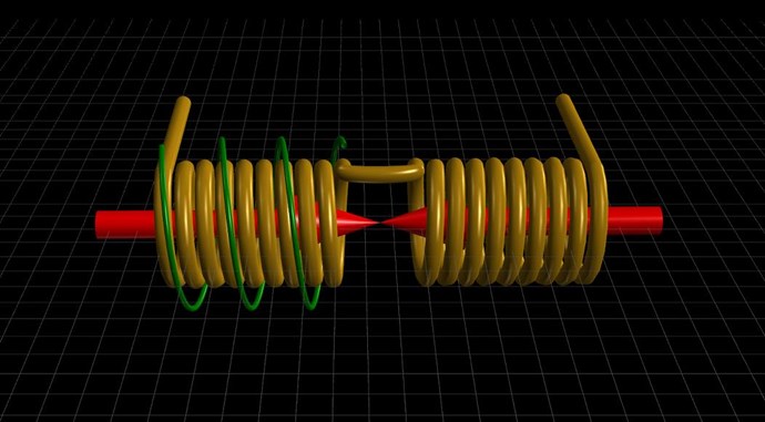
.  I spend some time plying with the device, nothing special so I will have to invest some  more time, changing the diodes drop the current from 1.25A to 0.75A which is a good sign, But a lot of noise as you can see from the photo (L3).

Have a nice day.

Chris posted this 30 December 2021

@Editor,

I see no plan here, no goal! What are you trying to Replicate? Which Machine, What Circuit? What Results are you looking for? What Waveforms are you aiming for?

What understanding have you achieved by reading the Threads here on this Forum? Do you know what we have achieved? And How we have Achieved it?

The Name of the Thread: "100w coils challenge" tells me you're here to make some sort of Community Challenge, but reading your content, shows me you have not yet read any of the Content in My Pages, so effectively you're wasting your time.

I will help you, if you lay out a path that clearly shows where you want to head, what machine you're trying to replicate and what your Goal is!

I would respect a thread name, something like: "Editor's Non-Inductive Coil Experiment Replication", then I would be able to see direction, and intention.

My Patience grows short, 2022 is going to be many peoples Worst Year Ever, and no one is preparing! It is already too late for most people, massive issues come very quickly and no one can see it, or if they do, they don't care!

Without Energy Machines, most of Humanity will be gone in a Year! Food Shortages are already occurring, and this is just the start! Food Prices are at all time High for some items! Some Items are simply not available!

I want to see Intent, Direction and clear set of Goals, please make an effort so I can see that, and help those wanting to help themselves wink Other wise I can not help thinking we have another Troll and I do not want to believe 9 of 10 new members are Trolls!

@All Humans, please take this Seriously!


A Professional, Determined Approach is the difference between Success and Failure!

Best Wishes,

   Chris

Chris posted this 31 December 2021

Hello Editor,

Your question:

What is the goal?


Learning how these machines work, so one can Build these Machines, with very little Effort and Minimal Cost, is the Goal!

Power P = Voltage V x Current I x Cos( Theta θ ) and Energy J = Power P x Time t. In the Pages on this Forum, I show how to achieve this very Simple Task! Those not willing to put in the Effort to Research and Learn, are doomed to Failure!

I can not help those not willing to help themselves!

Researchers that have taken the time to learn, should be able to build working Machines after a few tries, some here have achieved this task! Captainloz is one example!

Some people have searched for decades, right in front of them, all answers are here on this Forum, but no one wants to accept the Truth, evidence is not enough! Instead Bathing in Arrogance and Falsehoods is more desirable for them!

The Goal is, Learning what's Required to Build these Machines Easily and Cheaply!

Best Wishes,

   Chris

P.S: I just Upgraded My Power System, and you guys are going to be so amazed when you see the Actual Realization! Simple and Cheap, and you're being Ripped off soo much by the Power Companies! It amazes me how most people can not see such simple things!

editor posted this 31 December 2021

Hi Chris and a happy and healthy 2020.

Learning how these machines work, so one can Build these Machines, with very little Effort and Minimal Cost, is the Goal!

Completely agree, and the other quote that i have and teach my children is " help your self any you will be better". Currently it looks we are it the same room. Looking forward to see your upgrade in the power system.

The coil bobbins are made and painted. Today i I will wind some copper.


by


cd_sharp posted this 31 December 2021

Hey, @editor

If I may be of a little help, don't start with the bobbins. The bobbins are serving a specific purpose and define how your coils will look and work. Please have a serious read of Chris' threads and draw some conclusions about what the coils are supposed to do!

I hope you don't mind my intervening.

Stay strong!

"It's just the knowledge of the coils and how they interact with each other" (Stephen Mark)

editor posted this 31 December 2021

cd_sharp!


I don't mind, that's why it is a public thread.

All are welcome to post their opinions.

The info is everywhere on the forum, a bit confusing for me.

Sometimes it looks complicated, but the comments are " don't complicate, over doit"

Have fun!


editor posted this 05 January 2022

Hi,

i small update, as you can see on the photos how i manage to get the wooden shaft with the Plexiglas holders to secure the paper bubin so they can get lose during the process. Sorry about the mess.

I did't count the turns, but as you can see I have a neodymium magnet on the shaft to trigger the phone and 

count the turns ( Turns counter app). I took the 1mm wire and measure 20m long 2 times for L3 and L2.

L1 will be 1/4 lambda so 5m. Still waiting for some current shunt and then  i will wire all together with the  

gate driver IXD614.


by


editor posted this 16 January 2022

Hi Alexelectronic and all.


Sorry i did't see your previous comment. 

I did't test the coils with nothing, they are both wind with 1mm wire, 20m long.

For primary i use 5m or 2,5m wire. Then i play with the right tumb rule and changing the diode polarity.

It is far from anything, Currently I'm waiting for pcb's and other parts for sure it will not cost 20$, but i can add another zero to that.

It is simple they say,like riding a bike. On start it is almost impossible, but when you know it is is very simple, like everything in life.

Start at the beginning. Then you will probably have a few years of reading on the forum, then you will probably find out that it is not just 3 coils and a mosfet, the bulb will light but it will not be the name of the forum. Then you will probably have to spend years of reading on the forum.

Then you start researching further and you see that the smallest thing from the noise on the mosfet gate is important, which of course is not cheap. If you don't have a built-in oscilloscope in your head, you need this and a lot of other things, prepare the wallet.  Please don't take this comment of mime to seriously. It is just how i feel.

So good luck.


br


editor posted this 08 May 2022

Hi, everybody.


Time flies and some new progress. Finally got the core so the next step is to build the cores,for me one of the worst jobs is to build a nice coil former. I managed to draw and print one coil.The other one is still in the printing process. It takes about 4h for one pair.The two halves go nicely together since this is my first print and sketch.I needs just a bit of grinding, and it fits perfectly, will see how I will manage to wind the 1 mm wire and not to break something.

For some reason I cant add a photo... it is attached.


Attached Files

Chris posted this 20 May 2022

Hello Editor,

Yes, Delta B / Delta t will give you an approximation of Voltage V in POCTwo. POCTwo's Voltage will give you the Current via Ohms Law: I = V / R, therefore the MMF, can also be calculated, Turns N x Current I x Length l.

Now you can work towards increasing the MMF in POCTwo to assist your Input Coil, every increase in POCTwo reduces your Input for the same Output.

If only the other Forums were smart enough to work out this very simple, very basic set of Rules to Electrical Energy! They may be further ahead if they were just a little smarter 🤡

Best Wishes,

   Chris

editor posted this 30 December 2021

Hi Chris.   yes maybe you are right, maybe it is a challenge, for sure it is for me. What is the goal? The goal is to achieve above unity like the name of the site, I was thinking we are all here because of that, well maybe I'm not thinking in the right direction. If you don't like the name of the thread then changing it, you are the boss, and if you think that I'm a troll then delete my account immediately For sure I have some problems regarding the language, yes english is not my  primary language, but that is my issue. So to be a bit shorter, I will try to replicate a non inductive coil experiment and just maybe I can finally heat up the house with electricity, and not use any kind of  meter. It should be obvious that the machine is working. I was asking you before about what can be expected from the experiment, and your answer was, hmmm, no answer . Well that's how I got it. I hope i clear up some basic stuff.    have a nice day or night

cd_sharp posted this 31 December 2021

You're right, it is confusing for a newcomer. This is the best I can say and I'm repeating:

Please have a serious read of Chris' threads and draw some conclusions about what the coils are supposed to do!

Stay strong!

"It's just the knowledge of the coils and how they interact with each other" (Stephen Mark)

Chris posted this 09 January 2022

Hey Editor,

Thanks for sharing! Nice to see some experiment going on!

Set your goal: Power P = 100W = 10 Volts x 10 Amps

Setting your Goals:

  • "Generate" 10 Volts.
  • Pump 10 Amps
  • through Resistance: 1 Ohm


Then your Thread name will be realised!

Remember, the Electric Generator is a Machine that was never fully Engineered, they stopped before it was complete!

Let Partnered Output Coil One be your Armature Coil, and let Partnered Output Coil Two be your Rotor Coil, let your Input Simulate Delta t, the Time Rate of Change, very little current is required in this Coil! All Current is in your Partnered Output Coils!

Best Wishes,

   Chris

editor posted this 22 March 2022

Hello,

some new progress in between of other projects. I can tell you it is not fun when F16 are flying over your head few times a day.

Some people here are preparing for Mad Max scenario, buying gens, solar, long term food... and some live their lives like usual.

Nobody knows what is the best, but the realty is, that we went from one business to another in one day and the prices go up.

In the last post you can notice that I have big noise on the scope shot. After a little reading I added the 33000uf and put the ground. out, except from the scope. Happy with the result, now I just to figure it out how to get the triangle.

The small dry battery is for the driver and the big one ( not in the picture) is for the L1.

editor posted this 19 May 2022

Hello!


It looks like i finally finished the the device and now the first test.

As you can see on the photo, measuring the L1 the spike looks good but it is very height.

I'm putting in 2V and i got the the voltage on the coil 280v-300v. For IRFP250 this is the max voltage.

I have to limit the spike with 1nF capacitor attached to the coil to lower the spike to 230V (not on the photo). So guys what mosfets are you using?

My power to for the driver and the coil is from the battery but the scope is on the mains. Are you also using the battery to power the scope, regarding the ground?

have a nice day, e


Chris posted this 19 May 2022

Hello Editor,

WOW! Nice Work!

POCOne, as its magnetic Field Changes in Time t, will have a Magnetic Field of Density B. Have you calculated this Value by any Chance?

The δi / δt in POCOne produces POCTwo's Voltage, and therefore the Current in POCTwo is determined by: I = V / R.

The Magnetic Field from Each Coil must interact in a totally Asymmetrical way. If you think of this as a Balance of Force:


Imagine the Grey Box as a Current, its natural state is at rest. We want to move it, and as fast as we can! So, Our input Coil gives it a Push! As it stands, this is entirely Symmetrical! There is a Balance of Force: Equal and Opposite minus Losses, a Below Unity System! However, if we add another Force, Pulling the Current down the Wire, this gives us an Asymmetrical Force, we have: MMFOne + MMFTwo + MMFThree = MMFThree. We have assisted the Input Coil by a Factor of Magnitude, thus our Input Coil does Less Work, for the same Output!

The more MMF that POCTwo Adds to the System, the less work our Input Coil needs to do, all for the same Output, and thus the more Above Unity our System becomes! We must make up losses before we can break over the Unity Barrier.

I will help you along on this project! This is a very nice Build, very professional! I am Impressed!

Best Wishes,

   Chris

Chris posted this 21 May 2022

Hey Editor.

Yes, know where you are!

But, all Magnetic Fields, POCOne and POCTwo need to be increased, not just one, remember Equal and Opposite...

As your POC Magnetic Fields increase, your Input will Drop, the Input moves in the opposite direction! Your Input Coil moves in the other direction, because the Input Coil Impedance is Changed compared to what it normally is, its send in the reverse direction, instead of Reducing its Impedance and more Input Current Flowing, as a Conventional Transformer does, the Input Coil Increases its Impedance and the Input Current Drops as a Result.

If you read Floyd Sweets Notes, this is pointed out, and we know why and can explain this in Experiment:

Current limited by wire impedance only which increases dramatically in the oscillating field to several hundred KΩ (Calculated) – from impedance external to field of 2-3Ω (measured) at 400hz (loads down Oscillator). . No Explanation.

Ref: Floyd Sweet Lab Notes


Well, we, and only we, have an explanation for this, while other forums still haven't even noticed this statement even exists 😳

Yes, your Magnetic Fields and the Change of them in Time, is very important!

 Best Wishes,

   Chris

editor posted this 22 May 2022

Hello!

It is nice that you guys are taking the time and wrote here on my thread, thanks again.

Today I have again a few hours available to work on the 100 W challenge. I will see what can I do, 

honestly I'm not sure what exactly to do. 


Malendor, tnx, for explaining your ground system I have the same, regarding the large spikes I hope I have to plug in the 1000x probe.

Well see.

Nobody commented on the Mosfet that you are using!!

It is possible that I already blow up my mosfets and I even don't know it, or the diodes. It is possible that they are working fine on lower frequencies or if you measure one with the meter, but on high frequency they are not working us they should.


After spending some time in the lab some small progress.

I measure the L2 and L3 inductance at 10khz and the resonance frequency is at 10khz.

After changing the diodes at the measuring block and direction of L3 

The current went from 0.7A to 0.33A and I have a little light


br, e

Chris posted this 25 May 2022

Hello Editor,

Those mixed emotions come from unrealistic expectations from first experiments. I did warn you of this here.

If I may, please don't give up! keep working on this!

Measure the Input with POCTwo Connected and then Disconnected, watch the assisted force of POCTwo and calculate the difference.

Understanding why POCTwo is Assisting your Input is the first steps! Improving on this is the next steps!

Again, please don't give up! Your Goal is well within reach if you understand what it is you have achieved to date and keep improving on it!

Down Wind Faster then Wind, the same principles apply here:


POCTwo Pushes your Input right down, but this is a function of your Magnetic Field Strength and Density!

You can do it! And I will help you do it, but you have to stick at it and not give up!

Best Wishes,

   Chris

Melendor posted this 13 June 2022

Hello @editor

"" There are people here , that are so far ahead , that you wouldn't believe how far ahead  they are ""
Chris Sykes

The statement above, trust me , it is as real as it gets !!

10 x Current is not realistic for your / mine setup at the moment.
Try to use COP instead.
Cop 1.2 will be a good start.

Also , please decide where you want to place the load.
The coil with the load , will oppose your input coil , Equal and Opposite !

If you have L1 TRIGGER and L2 with the load on it , that means L1 and L2 are 180 out of phase , because of LENZ law.

Now ,  ..... Logic dictates , that if the 2 coils fight , if you place a 3rd coil into the setup  ( L3 ) that coil  MUST Oppose / HELP one of the L1 / L2.
There is no other way.
The flux in L3 can go either left ...or right . opposing or aiding.

!!!!!!! There are lots of Cases where the Voltage in L3 is 0.1V . That means , the Current in POC 3 , is so low , that it will not do anything.

Investigation of L3 must start after you get L1 and L2 correct.

My personal opinion is that you disconnect L3 ,  and try to get a good transformer with L1 - L2.
Over 90% efficient.

This was just my 2 cents Editor.
I wish you good luck with the journey.

~~~ Melendor the Wizard

editor posted this 30 December 2021

The coil bobbins will be finished tomorrow.

Dimensions of the bobbin is 80x30x30mm, i will use the wire that i already have 1mm. 

What do you guys think of winding L1 2 layers ( 1 layer 80T) all together 160 turns.

On L1 coil then L3 winding with 40 turn, to use 1:4 ratio.


br


Chris posted this 31 December 2021

@Editor,

The guys are right! In Faradays Equation: E.M.F = -N dΦb / dt, it can be calculated that b / dt is partly dependent on Coil Geometry. This is covered here on this Forum, Here. Also in other places. Magnetic Field BMax is dependent on Coil Length l. This is a VERY Important factor in the "Generation" of Voltage! As is Cross Sectional Area CSA!

I hope you can see we are only trying to help, give Direction and a Path forward?

Best Wishes and Happy New Year! Please prepare for 2022 like no other year!

   Chris

editor posted this 09 January 2022

Hi all.


Connecting the experiment, and play a bit with the device, before connecting to the scope.


have a nice weekend.

br


Alexelectronic posted this 16 January 2022

Hi all.


Connecting the experiment, and play a bit with the device, before connecting to the scope.


have a nice weekend.

br

Hello greetings can you give the data with which you tested the coils please
And how did the tests go, you can comment on them

Alexelectronic posted this 16 January 2022

Hello, I read your good comment

Chris

P.S: I just Upgraded My Power System, and you guys are going to be so amazed when you see the Actual Realization! Simple and Cheap, and you're being Ripped off soo much by the Power Companies! It amazes me how most people can not see such simple things!

You already published it, I would like to know it, I am going to start doing your projects, where to start
Thank you

Melendor posted this 21 May 2022

Hi Chris!


.If I'm correct you are just traying to say that I have to 

increase the current in L1 to get the proper ( large)  magnetic field so that the  L2 and L3 can start singing.

in this case my L1 is to long, has too many turns. 

Hello Editor and thank you for posting.

I was in the same situation as you and Chris has helped me to understand.

It is the CHANGE in current in the L1 that decides how much Voltage will have on POC1.
You can have 10 Amps in L1 , but if the change of that current is very very slow , you will get 10 V on your POC's ( for example )

As a beginner , you could keep the current between 0.3 - 0.5 A on the trigger L1. ( Not to damage your equipment )
As Chris has said in his YouTube videos "" You need some Current to make this work ""

Are you also using the battery to power the scope, regarding the ground?

I personally use the Scope grounded to mains.
I am trying my best not to blow it up.
The power supply is not grounded , because it will form a Ground-loop ,and that will damage the equipment.

I wish you all the best.
~~~ Melendor the Wizard


editor posted this 24 May 2022

Hello!


After 2 days of intensive work some progress. For now i just burn 2 bulbs.

I did loft of experimenting with the device, make one big mistake that  took me some time to figure it out.

Measuring problem, but i fix that.

Later on i was playing with the device with:


  • different loads, 2w, 5w, and 20w bulb
  • different voltage on L1 from 3 to 12V
  • different turns on L1
  • gap or no gap on the core
  • measuring the natural frequency of the coils ( 11khz, 31khz, 130- 150khz)
  • polarity of diodes and L1 current flow direction

I can get the triangle waveform measuring the current on L2 ( bulb) but I'm far from 10v and 10A.

When the light is nicely bright!

Any ideas how to increase the triangle?


b,re


Chris posted this 24 May 2022

Hey Editor,

Very Nice Work! Well Done!

To answer your question, one needs to know what we are looking at.

The Oscilloscope reads this Amplitude on the scope is the Voltage Difference between Ground and Positive on the Probe Tip.

We know from Threads here on this forum, that Voltage is "Generated" in a Conductor when:

  1. Magnetic Field Density B - From initial to Max.
  2. Time Rate of Change of this same Magnetic Field - Time in Seconds.
  3. Number of Turns N - That are exposed to this same Magnetic Field.


Of course Lenz's Law gives us the Sine, or polarity, of the "Generated" Voltage, which will be opposite, if one applies the Right Hand Grip Rule.

Now, one needs to figure out what the exact process are to Induce this Voltage Amplitude. 

Of course, as B increases as does V, so making your Coils Voltage Higher means increasing your Magnetic Field or Turns.

Some years ago, I came to the conclusion that, we must do this for ourselves to help ourselves! No one is ever going to help us!

Best Wishes,

   Chris

editor posted this 25 May 2022

Hi Chris!


Currently I have very mixed emotions how to proceed with the project.

Maybe I need some time off and see what the universe will bring.


have a nice day, e

leonel posted this 25 May 2022

Nice Editor and thank you for all your efforts. 

Those word mean...The objective was achieved? 🙃

editor posted this 11 June 2022

Hi!


the forum was down for the last day at my location, try it from 3 different ip-s, with no luck.

But today is another day and it is working, great. I got electrocuted yesterday, and that shock bring

the smile on my face. As I can see i got my voltage up, with 6v and 0.6A at the L1. I did quickly try the diode and the bulb 

but no juice, yet...

Here is a short video, till now i was just reading that is possible to get such a high voltage, but no video or photo.

editor posted this 13 June 2022

Hello Everybody


Here is a short video with the load on Poc1 and Poc2.

Nothing special. There are some better results because of the lower load. ( both bulbs after the diode)

The current goes down on the POc2 if i short the coil (poc2) bub just a little bit.

But I still did't hit the resonance or the superconductivity where the current can be 10x higher that on the »normal« mode. I looks I'm fare, fare away from lightning a 100w bulb.

I was reading a lot lately, making notes from the forum, but I notice that nobody eventual got out even 50W. Maybe it did, please If you know who and where remind me please.

Chris posted this 13 June 2022

Hi Editor,

Melendor is accurate in his post, wise advice was given!

About 4 Weeks ago we spoke about calculation of your Magnetic Fields, did you get around to doing this?

Of course, it is the Magnetic Field Interactions that are key to making this work, as has been advised for many years:


The "Bucking Magnetic Fields" Pumps Current. A COP of 1.7 is not a hard target if one is to follow the advice given and accurately replicate the procedures given. Many here have achieved various different results, some better than others. The degree of success depends entirely on the Magnetic Field Density and Strength. Which of course is the same Variable that defines an Electric "Generators" Output.

Electromagnetic Induction is Incomplete, currently it is entirely Symmetrical! We, www.aboveunity.com have added the Asymmetrical part to Electromagnetic Induction, giving Faradays Law the other half of Electromagnetic Induction that was missing!

Best Wishes,

   Chris

Melendor posted this 19 June 2022

Hello editor , Chris and everybody.

It is true ,that we can not talk about over-unity , if one has not learned the basics.
One must keep the Equipment safe and himself and others safe , and for that some basics are required.

The transformer , it looks easy , but is it ?

The learning material on transformers , is not that great on the internet.
Chris was right when he said , that nobody talks about the CURRENT in the secondary.

You will find lots of people from India with youtube videos ,  where they talk and talk and talk about :
- Dots , + , - , step up - step down , grid frequency 60 Hz , polarity change  etc 

All the information above , and you will not learn one thing about the Current in the secondary.
Also the information above is valid , and talked about . with a SINE wave , that is Positive 120 V and negative 120 V.

We are using pulsed DC that is positive and 0.

This forum is light years ahead from any other forum on the Internet !!!! ,
In this situation , why not be the first forum ,that INVESTS in his members ??
Why not make a Transformer Thread ( 2 coils ) , to see scope shots , current flow , diodes direction etc. ??
If one understand the interactions between the 2 coils , that one can add the 3rd coil , 4 coil etc

All I want to say friends , is that with information from other forums , Wikipedia , google images , etc a standard member from TRIER 1 , will never ever get good results , not now , not in 1 century.
I am not he Owner here , and I do not make the rules ,but hell Yea , I would love to see step by step material on whatever subject.

Stay safe everybody !


!!! Melendor the wizard


Chris posted this 20 June 2022

Hey Melendor,

Regarding your statement:

This forum is light years ahead from any other forum on the Internet !!!! ,
In this situation , why not be the first forum ,that INVESTS in his members ??
Why not make a Transformer Thread ( 2 coils ) , to see scope shots , current flow , diodes direction etc. ??
If one understand the interactions between the 2 coils , that one can add the 3rd coil , 4 coil etc


I completely agree!

I have shared many hundreds of hours of experiments on Electromagnetic Induction:

https://www.aboveunity.com/thread/simple-electromagnetic-induction-experiment/

https://www.hyiq.org/Page/Details?Name=Support


Pretty much every video I have released includes information on how to make this work. Includes information on Electromagnetic Induction!

Many hundreds of hours of detailed information, including my Series: Chris's Non Inductive Coil Experiment:


There is no need for Tier II or III they are irrelevant and not of any use, no secrets in those threads! All information is shared openly!

It only takes Minds which are ready to learn something new! That's All!

Any one can do this! Any one!

Best Wishes,

   Chris

Chris posted this 23 June 2022

Hello Editor,

Didn't want to mention before, but Itsu was telling me that this will happened and it did.


Thank You for letting me know! I appreciate one thing about your approach: "Reading between the lines is very informative!" I had a feeling you were part of that crowd! My Gut Feeling proved true again!

We have had immense trouble with Trolls starting back in 2015 when I bought out this Technology in the Public Domain, we have dealt with them with a swift stern hand, sweeping them away as fast as we can, this is why we have been so Successful, more Successful than any other Forum Ever!

You see, we have a very good image depicting this behaviour:


You don't have to wait for seven days, lock it now. It is better for everyone, especially the new members seeing the important questions not answered. 


I will proceed and lock this thread as you wish!

Its a real shame you failed to follow any of the guide we provided! It is so easy to fail when one chooses to!

This should be a Very Enlightening Read for many many Readers! Very Enlightening!

   Chris

Chris posted this 17 March 2022

Hello Editor,

Best wishes to you and all. Stay safe and well!

Great work Thanks for sharing!

Best wishes,

   Chris

  • Liked by
  • Jagau
  • Augenblick
editor posted this 20 May 2022

Hi Chris.


Thanks for you kind reply. No I didn't calculate the magnetic field density B.

I presume I need to use the you calculator?

I was checking the Permeability of the core Amcc320 and i didn't fine the info, unfortunate

My L1 is 4m long 1.5mm2 the current is 0,3A, 24 turns.


br, e

  • Liked by
  • Chris
  • Augenblick
editor posted this 21 May 2022

Hi Chris!


Really appreciate your input on my build, thanks again.

I will be honest I'm good in building but not math and the staff,

so i will try to translate this to my head language. If I'm correct you are just traying to say that I have to 

increase the current in L1 to get the proper ( large)  magnetic field so that the  L2 and L3 can start singing.

in this case my L1 is to long, has too many turns. 


have a nice weekend everybody, e

  • Liked by
  • Chris
  • Augenblick
editor posted this 25 May 2022

Hi Leonel!


No the objective was not achieved. The words meant, hmm better not to write something that I will regret. 

I'm a bit sad since here are 575 members and maybe you can count in two hands successful aboveunity devices with very low output power of course. Well see...


br, e


  • Liked by
  • Chris
  • Augenblick
editor posted this 26 May 2022

Hi Chris.


I did what you told me to do. When I have this small triangle on the scope withe the large spikes

the current on L1 is 0.850A when the L3 is connected. When L3 is NOT connected the current drops to 0.755A.

So it is obvious  that L3 is not assisting the L1. The difference is almost 100mA. Afterwords I also again swap L3 

cw/cww and diode change. The difference was triangle and no triangle. One more thing that I notice, the current can slightly

change depending on the position of the L3 on the core ( midle, far left or far right)


br, e

  • Liked by
  • Chris
  • Augenblick
Chris posted this 26 May 2022

Hey Editor.

Sounds like you have the L's interpreted differently, either way, one Coil assists your Input Coil if you work through the Magnetic Field Vectors:


If POCOne and POCTwo Oppose each other, then one must always assist the Input Coil, right?

So, if you have the configuration correct, and your L's are interpreted differently, then:

  • 0.850A / 0.755A = 1.125 x 100 = 112.5%.
  • 0.755A / 0.850A = 0.888 x 100 = 88.8%.


So you can see a difference between the Coils Connected and Disconnected, which is one of the effects that is important to observe on the path forward.

Wistiti shows you how to do it in this video:


Experiment and looking for the right effects is how you will succeed!

Best Wishes,

   Chris

  • Liked by
  • Jagau
  • Augenblick
editor posted this 28 May 2022

Hi Chris!


I was playing again with coils, and also change the primary with 2.5mm wire.

Here are the results, measuring the voltage and current on the DC-DC inverter at the battery.

Poc2 OPEN TERMINALS

8.2V

0.405A


Poc2 diode connected (measuring block)

8.2V

0.455A


Poc2 change the polarity of diode

8.2V 

0.450A


Poc1 (load) changing the diode polarity

8.2V

1.325A


I don't get it, the lowest current is when the Poc2 is not  working ( open terminals)!!

Still thinking about it, I got the triangle effect, but from the input current it looks like my Poc2 is not helping

the primary at all.


br, e


  • Liked by
  • Chris
  • Augenblick
editor posted this 09 June 2022

Hi,


Some new progress. I print a couple of new coil former's and make new version of it.

Basically I started from the beginning, ending up with some new pair of coils and use all of my 5 kg copper wire.

The last pair is nicely wound with the natural frequency of 266 Khz on the spot for both coils.

Today I just wound the primary and check the switching. The scope shot is taken on primary with the open L2/L3,

to me it looks good!


br, e


  • Liked by
  • Chris
  • Augenblick
editor posted this 11 June 2022

Hi Chris!


Is there any short manual, cheat code hot to find the magnetic resonance? 

I already sweep the coils almost from 0 to few 100 khz, but no V8.


br, e

  • Liked by
  • Chris
  • Augenblick
Chris posted this 11 June 2022

Hey Editor,

Its very easy, POCOne and POCTwo must be 180 degrees out of Phase and Approximately Equal in Amplitude. Thus Bucking Magnetic Fields, where the Vector Sum of POCOne and POCTwo equals Zero. No net effect on your Input Coil.

A Voltage is "Generated" ( Charge Separation ) and a Current is "Pumped" ( Magnetomotive Force ), its worth focusing on this very easy to prove fact.

Best Wishes,

   Chris

  • Liked by
  • Augenblick
  • Melendor
editor posted this 14 June 2022

Hi Melendor and Chris!


Nice to see some good replay. I will investigate and do some more testing.

When I got some good news I be back.

Just watch the Above Top Secret - The Technology Behind Disclosure documentary, nice if you have a chance watch it.

br,e

  • Liked by
  • Chris
  • Augenblick
Chris posted this 16 June 2022

Hey Editor,

I want to invite you to join in on the thread: "Melnichenko's Effect"

I believe this will help you in the Effects of the Coils on this thread.

Best Wishes,

   Chris

  • Liked by
  • Melendor
  • Augenblick

Topic Is Locked

We're Light Years Ahead!
Members Online:

No one online at the moment


What is a Scalar:

In physics, scalars are physical quantities that are unaffected by changes to a vector space basis. Scalars are often accompanied by units of measurement, as in "10 cm". Examples of scalar quantities are mass, distance, charge, volume, time, speed, and the magnitude of physical vectors in general.

You need to forget the Non-Sense that some spout with out knowing the actual Definition of the word Scalar! Some people talk absolute Bull Sh*t!

The pressure P in the formula P = pgh, pgh is a scalar that tells you the amount of this squashing force per unit area in a fluid.

A Scalar, having both direction and magnitude, can be anything! The Magnetic Field, a Charge moving, yet some Numb Nuts think it means Magic Science!

Message from God:

Hello my children. This is Yahweh, the one true Lord. You have found creation's secret. Now share it peacefully with the world.

Ref: Message from God written inside the Human Genome

God be in my head, and in my thinking.

God be in my eyes, and in my looking.

God be in my mouth, and in my speaking.

Oh, God be in my heart, and in my understanding.

Your Support:

More than anything else, your contributions to this forum are most important! We are trying to actively get all visitors involved, but we do only have a few main contributors, which are very much appreciated! If you would like to see more pages with more detailed experiments and answers, perhaps a contribution of another type maybe possible:

PayPal De-Platformed me!

They REFUSE to tell me why!

We now use Wise!

Donate
Use E-Mail: Chris at aboveunity.com

The content I am sharing is not only unique, but is changing the world as we know it! Please Support Us!

Thank You So Much!

Weeks High Earners:
The great Nikola Tesla:

Ere many generations pass, our machinery will be driven by a power obtainable at any point of the universe. This idea is not novel. Men have been led to it long ago by instinct or reason. It has been expressed in many ways, and in many places, in the history of old and new. We find it in the delightful myth of Antheus, who drives power from the earth; we find it among the subtle speculations of one of your splendid mathematicians, and in many hints and statements of thinkers of the present time. Throughout space there is energy. Is this energy static or kinetic? If static, our hopes are in vain; if kinetic - and this we know it is for certain - then it is a mere question of time when men will succeed in attaching their machinery to the very wheelwork of nature.

Experiments With Alternate Currents Of High Potential And High Frequency (February 1892).

Close