Zanzal's MultiTapped Transformer Test Platform

  • 1.3K Views
  • Last Post 05 March 2019
Zanzal posted this 20 November 2018

So here is a little thing I shared with Chris earlier. He thought others might benefit from it and asked me to share it with a larger audience. I'm not making any claims at this time, but this device has done some strange things. I managed to destroy several 12-15W loads with it in under a second. I would urge caution and remind would be experimenters that this device will generate alternating currents that can be hazardous to one's health...

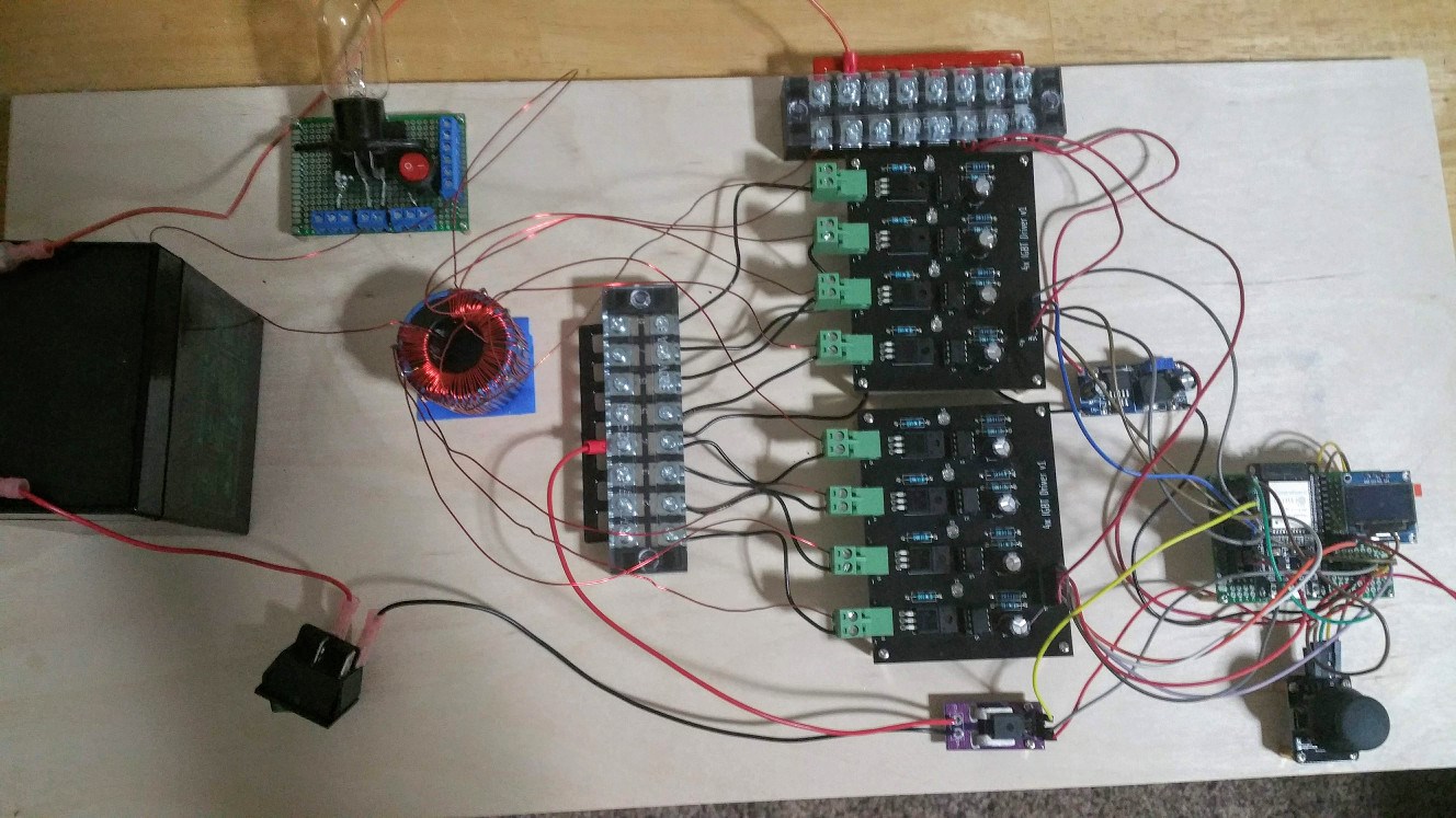
Here is my circuit summarized:

JS Circuit

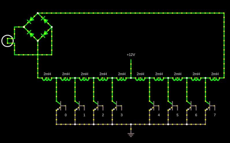
I'm not sure what to call my device or even if its worth naming at this point. The long string of inductors is simply a multi-tapped transformer wound on two stacked "nanoperm" toroids. I'll be experimenting with different configurations for the transformer piece so there may be better designs, but I'll include a picture to make it more clear.

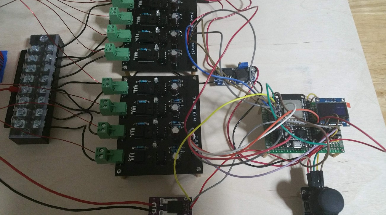
The transistors shown in the schematic are IGBTs that do not have a reverse diode..They are controlled by an ESP-32 MCU. 

There is a special firing order involved with the IGBTs. It is:

3 -> 4 -> 2 -> 5 -> 1 -> 6 -> 0 -> 7

When 4 is turned on 3 gets turned off, etc. For a given frequency f, a complete cycle would be completed. So at 60Hz this cycle is completed 60 times in one second. The on time for each step is not equal. The inductors close to the voltage source are on the least time. The timings are:

0 = 0.20, 1 = 0.15, 2 = 0.10, 3 = 0.05, 4 = 0.05, 5 = 0.10, 6 = 0.15, 7 = 0.20

I may also experiment with linear timings, but I don't think they will give better results. There is also an oscillatory version I am using that cycles back:

3 -> 4 -> 2 -> 5 -> 1 -> 6 -> 0 -> 7 -> 0 -> 6 -> 1 -> 5 -> 2 -> 4

To correct for the extra steps each timing is divided by 1.6. To explain this with integer math, lets say you were using an 8Mhz CPU and you could control timing by delaying for a certain number of clock cycles, if you ran this at 1000Hz, you would complete a full cycle in 8000 clocks. So you would turn 3 on for 0.05 * 8000 = 400 cycles. but when using the oscillatory version 3 would be on 0.05 / 1.60 * 8000 or 250 cycles. Anyway this is pretty much all there is to this thing. 

Feel free to build it and experiment. If you do this I recommend starting with the oscillatory pattern, it seems to be the better one. I also have tried other patterns but they are not giving good results. Still there are a lot of permutations possible so feel free to play around with other ideas.

Order By: Standard | Newest | Votes
Zanzal posted this 20 November 2018

Some pictures:

Attached Files

Zanzal posted this 20 November 2018

One difference between the picture and the schematic. I switched to an AC microwave oven bulb since my 12V DC bulbs were getting destroyed. The hardware specifics don't really matter all that much IMO. The main element here is: Timing (and maybe the transformer core). I'm still trying to figure out how important the transformer design is, and also if IGBTs without the anti-parallel diode (but turn off slower) work better than mosfets.

The device has some quirks. I can actually render it non functional by using certain firing patterns. It seems to cause some sort of issue with the transformer cores. If I leave them alone for a bit they reset. Very strange stuff. I may go into detail about some other patterns, but for now I'll just put out helpful information. I thought it worth mentioning though in case people decide to experiment, permanent breakage could be possible, and may be in line with other experimenters who encounter issues after long durations.

Jagau posted this 20 November 2018

Hi Zanzal
Congratulations very nice setup
Just a question, I did not understand what the device does
when you have time, can you explain to me again?


Jagau

Vidura posted this 20 November 2018

This is a interesting device Zanzal. I just want to comment that I had a similar setup in mind for a solid state version of figueras part G(not the switching orders you used) . As Aetherholic used this type of material in his built and had very good results. It might be worth to make a test with equivalent switching patterns(make before break, at least two switches active simultaneously), this would produce a coilshorting in a sequencial manner. I will not build it for the instance, as I have to many proyects for complete now . Regards Vidura

Zanzal posted this 20 November 2018

Hey Jagau,

For me this is a good platform for research. I can swap out transformers and test different ideas on a single board. I think perhaps my answer to Vidura may help make it more clear.

Hey Vidura,

In my firmware I created 5 basic programs and derived 5 oscillatory versions. By oscillatory I mean the sequence reverses once before stopping at the place it started. The 4 sequences I didn't include above are:

0 -> 1 -> 2 -> 3 -> 4 -> 5 -> 6 -> 7 (Sweep)

3 -> 7 -> 2 -> 6 -> 1 -> 5 -> 0 -> 4 (Interleave+Sweep)

3 + 4 -> 2 + 5 -> 1 + 6 -> 0 + 7 (Twin)

3 + 7 -> 2 + 6 -> 1 + 5 -> 0 + 4 (Twin+Sweep)

All my patterns are reversible, can be oscillated, and can be given linear or weighted timings. I believe weighted is the better approach and so far no testing has revealed differently. I believe what you are describing with coil shorting may be similar to the pattern I named "Twin" above. It causes power to flow through both branches at the same time. This is not necessarily the same as shorting though. It may be possible to implement shorting through bipolar transistors but I don't see this as possible using mosfets or IGBTs since they turn on based on a voltage differential between the source and the gate. I could be wrong though. Something to experiment with later...


Chris posted this 21 November 2018

My Friends,

Thank you all for supporting Zanzal's work as you have! Seven Thumbs Up is the most I have seen.

This is very important work! Massive potential lays in this device and Zanzal deserves all the credit for his genus!

@Zanzal, perhaps a few Parallel Caps may increase the output some more. Reactive Power can be used to increase the Current well beyond the standard Current Level by applying a 12 volt potential across the winding.

I will do a post on this later on.

Awesome Work Zanzal and thank you so much for sharing! Awesome!

   Chris

  • Liked by
  • Zanzal
Zanzal posted this 21 November 2018

I added another variable to the mix, a duty cycle. If 100 the device operates as described, otherwise it stops the flow of current early for each step. This led to a new discovery. The operating mode twin, actually is potentially more powerful than I had thought, at 100% twin is easily the worst mode, but at between 50% and 75% it appears to outperform the other modes in some respects.

This is a very strange result. I am not sure why this is. I was not entirely surprised when I first started playing with this thing that twin seemed bad since for AC one might expect the voltage potentials to be equal since current is flowing symmetrically.. But something is happening when the duty cycle is reduced. There is of course a slight timing difference because my microcontroller doesn't turn them both on at the exact same time there is a small offset perhaps 1.5us or so.

  • Liked by
  • Chris
  • cd_sharp
Chris posted this 21 November 2018

Zanzal and all,

Youre right, I cant prove this but have suspected this before several times.

It does appear a timing delay, where the switching is not 100% perfect, can increase the chances of coils becoming more advantageous!

I have used a H-Bridge as you know, and the old one gave me better results most of the time, and I believe that's because the switching was not clean and smooth, leaving somewhat of a delay on one or more Coils.

Excellent observation Zanzal!

   Chris

  • Liked by
  • Zanzal
  • Aetherholic
alohalaoha posted this 21 November 2018

Hey Zanzal

Good work man. You have reinvented the bycles. In positive mean of course. This configuration has remembered me of one very old extraordinary device invented by Japanesse EE Shinichi Seike "Gravity strain energy absorber". Same cyclotrone configuration setup like yours, but he used only 3 transistors switching cycle. He used 3 indpendent signal generators for each transistor with tunable phase shift adjustments.

Maybe you could find some new ideas from his work

http://www.rexresearch.com/seike/PrincipUltrarel.pdf

There very probably could be some unknown process of energy extraction. Simillar configuration used Stiven Maprk in his TPU and Inogda in his TPU replication. From Inogda's work (i had knew him) i know he had succeed to release very big amount of infra red radiation at output of his TPU with very small current consumption. Simply incandescent light bulb had gave very weak ligh but enormous IR radiation. Then he has simply disappeared several month later. Never heard any news from him because he has lived in Donbas (DNR republic). In that time there was a civil war made by American Cabal Neocones. One one their bloody games in Matrix's virtual reality whre we all live.

Best wishes

Aloha

  • Liked by
  • Zanzal
  • Chris
alohalaoha posted this 21 November 2018

About the strange cycling of energy flow i have just remembered some beautiful words from Arktika Arvet (Arctic Vedas).

Quote"When the the AR penetrate the darkenss OM, the vortexes are born, which tear from the darkness, many stagnant substances from the frozen Fire, from which were produced all worlds of matter and throw them outside (of darkness). This movement is accelerated by the aspiration of the AR, attracted by infinite abyss. This is how the new center of AR take place in the infinite abyss.".

Maybe one the best remoteview pictured by Charles Leadbeater and Annie Besant.

Zanzal posted this 21 November 2018

I think I've done all the testing I can with this setup. Lots of issues identified and solved, but lots more I cannot solve. Main issue is that the peripherals attached to the MCU are proving unreliable. The OLED screen on the i2c bus flickers and goes in and out of readability when the IGBT drivers are in use. This happens whether power is flowing through the transformer or not, but is worse when it is being tested. I am not getting reliable power readings from the hall sensor so it needs to go. I believe a large portion of the fault is with the microcontroller itself. It is a version 1, there have since been made many other versions. I am going to upgrade to the latest design and see if that solves the problems before continuing.

Part of what I wanted to do with this project is come up with a design for reliably measuring input and output power when the device is in use. Not having a reliable i2c connectivity is going to completely ruin that idea. But if I can find a new ESP-32 board design that doesn't have these issues I may design some isolated i2c current sensors based on ISO1540 and INA260. This would allow me to measure power (input and output) without sharing a ground. Being able to compare input and output power from within the MCU allows for many other wonderful ideas.. like having the device automatically adjust settings to the power requirements of the load, or auto-resonance tuning, etc. If anyone has serious experience with electronic design and is willing to help or take up the challenge let me know, otherwise I'll be working on this over the next few weeks or months. This project is entirely an open source effort everyone is welcome to ignore or participate as they wish. 

To be continued...

  • Liked by
  • Chris
  • Aetherholic
Zanzal posted this 22 November 2018

This is very important work! Massive potential lays in this device and Zanzal deserves all the credit for his genus!

Thanks Chris, I guess I missed your post earlier. Yes, I don't think its as much my idea alone but rather a product of the hard work of many of the people who contribute to this body of knowledge we've collected here. The work is inspired by Figuerra first and foremost. As Vidura had mentioned it looks like something he imagined for a solid state part G. Vidura is of course correct. This is how the idea started for me as well, a solid state version of Figuerra's part G.

Part of the reason I posted it outside of the EBC is that I think it deserves to be set free so that others can experiment with it freely. My hope is that others freely give as they have freely received. That can only happen when people start by sharing. While its always great to acknowledge individuals for their contributions, which perhaps in my case is the timings and in the future some PCBs and firmware, its not necessarily entirely my own idea and it would be wrong of me to claim otherwise.

@Zanzal, perhaps a few Parallel Caps may increase the output some more. Reactive Power can be used to increase the Current well beyond the standard Current Level by applying a 12 volt potential across the winding.

I'll give that a try when I can, the problem I'm having ATM is the system is increasingly unstable which is largely a microcontroller problem since the issues are encountered at rest. Hopefully I can resolve this issue without having to switch microcontrollers. In the meantime I need to research a better bridge rectifier. My device is operating well into the 10-20kHz range and if I want to convert it to DC efficiently I'll need a beefier bridge rectifier that can handle those frequencies. So plenty of research to do.

Zanzal posted this 28 November 2018

Good work man. You have reinvented the bycles. In positive mean of course. This configuration has remembered me of one very old extraordinary device invented by Japanesse EE Shinichi Seike "Gravity strain energy absorber". Same cyclotrone configuration setup like yours, but he used only 3 transistors switching cycle. He used 3 indpendent signal generators for each transistor with tunable phase shift adjustments.

Maybe you could find some new ideas from his work

http://www.rexresearch.com/seike/PrincipUltrarel.pdf

There very probably could be some unknown process of energy extraction. Simillar configuration used Stiven Maprk in his TPU and Inogda in his TPU replication. From Inogda's work (i had knew him) i know he had succeed to release very big amount of infra red radiation at output of his TPU with very small current consumption. Simply incandescent light bulb had gave very weak ligh but enormous IR radiation. Then he has simply disappeared several month later. Never heard any news from him because he has lived in Donbas (DNR republic). In that time there was a civil war made by American Cabal Neocones. One one their bloody games in Matrix's virtual reality whre we all live.

Hello Aloha, though initially I did not understand where you were going with this, I re-reviewed JL Naudin's G-Strain research and I think I understand it a little better now than last I looked at it.. Very interesting indeed! I think see why you associate that work with the TPU. I had not made the connection until I re-reviewed JL Naudin's research. JL Naudin did replicate the G-Strain device and his was able to achieve a COP of over 1.5. I am not saying I agree that this is similar to the circuit I am using, in fact it is very different to me, but I understand why it reminded you of that. In fact JL Naudin's replication has no coils at all, except for the two conductive rings which would probably have some small mutual inductance. I'll consider these interesting things as I do more research. Thanks!

  • Liked by
  • Chris
  • Aetherholic
alohalaoha posted this 03 March 2019

Hey Zanzal

after long time of analysing Floyd Sweet VTA and Auto-Chip BTG, G.T. Kasyanov Electron Accelerator, i can see a high similarities with your circuit design.

If you still have working circuit at your lab workbench i can give you some of my observations and remarks.

I think you are very close to full working example of free energy generator.

Best regards

Aloha


  • Liked by
  • Chris
  • Zanzal
Zanzal posted this 04 March 2019

Hey Aloha,

I've not been able to get the results I was looking for out of this or any of the other multi-coiled systems I was working with so I'm taking a break from it for awhile. I've got some other research I want to do, but will likely pick this up again later. Feel free to share your ideas.

alohalaoha posted this 05 March 2019

Hey Zanzal

Your schematic is very interesting for me because it has many joint points with my idea. Probably you have missed something important. For example external time varying B-field perpendicular to your coils. If we imagine magnetic field like a stream of etheric energy flow, cycling in the infinite cycles, perpendicular to your switching coils, than precise time sequency of coil shorting behave like an etheric compressor due to primary current flow through them. Switching has cummulative compression effect on extrenal field which could be imagine like a squeezed spring. This make great disbalance effect in ether which i think would very violently try to remade disbalance, injecting high energy pulse into your swithing coils, releasing the spring until next compression cycle.Maybe i am wrong but i am sure that process of generating AU energy must be extremely simple, because all high compexity systems tend to simplycity. This is my understanding of process, which Floyd Sweet had described in his work like change of energy flow aspect ratio. Or to say mch simple, changing geometry of etheric field in the visinity of disblance source.

Regards and good luck

Aloha


We're Light Years Ahead!
Members Online:
What is a Scalar:

In physics, scalars are physical quantities that are unaffected by changes to a vector space basis. Scalars are often accompanied by units of measurement, as in "10 cm". Examples of scalar quantities are mass, distance, charge, volume, time, speed, and the magnitude of physical vectors in general.

You need to forget the Non-Sense that some spout with out knowing the actual Definition of the word Scalar! Some people talk absolute Bull Sh*t!

The pressure P in the formula P = pgh, pgh is a scalar that tells you the amount of this squashing force per unit area in a fluid.

A Scalar, having both direction and magnitude, can be anything! The Magnetic Field, a Charge moving, yet some Numb Nuts think it means Magic Science!

Message from God:

Hello my children. This is Yahweh, the one true Lord. You have found creation's secret. Now share it peacefully with the world.

Ref: Message from God written inside the Human Genome

God be in my head, and in my thinking.

God be in my eyes, and in my looking.

God be in my mouth, and in my speaking.

Oh, God be in my heart, and in my understanding.

Your Support:

More than anything else, your contributions to this forum are most important! We are trying to actively get all visitors involved, but we do only have a few main contributors, which are very much appreciated! If you would like to see more pages with more detailed experiments and answers, perhaps a contribution of another type maybe possible:

PayPal De-Platformed me!

They REFUSE to tell me why!

We now use Wise!

Donate
Use E-Mail: Chris at aboveunity.com

The content I am sharing is not only unique, but is changing the world as we know it! Please Support Us!

Thank You So Much!

Weeks High Earners:
The great Nikola Tesla:

Ere many generations pass, our machinery will be driven by a power obtainable at any point of the universe. This idea is not novel. Men have been led to it long ago by instinct or reason. It has been expressed in many ways, and in many places, in the history of old and new. We find it in the delightful myth of Antheus, who drives power from the earth; we find it among the subtle speculations of one of your splendid mathematicians, and in many hints and statements of thinkers of the present time. Throughout space there is energy. Is this energy static or kinetic? If static, our hopes are in vain; if kinetic - and this we know it is for certain - then it is a mere question of time when men will succeed in attaching their machinery to the very wheelwork of nature.

Experiments With Alternate Currents Of High Potential And High Frequency (February 1892).

Close