Zanzal's Longitudinal Wave Research

  • 2.4K Views
  • Last Post 23 May 2020
Zanzal posted this 19 May 2018

Greetings Friends,

After my puzzling adventure with the Lenz Free Pickup coil I was somewhat exasperated by all of the anomalous behavior I witnessed. I did attempt to describe some of it, but I am no Tesla. I have a very dim grasp of what I am dealing with and while I enjoy hearing the tales of people who talk about mysterious phenomena when I go to do an experiment or replication I put on my scientist-wanna-be hat and attempt to approach things as objectively as my human nature allows. I came to the conclusion that conventional circuit theory simply doesn't do a good job of explaining how electricity can propagate through a single wire. Even if I pretend I have a virtual capacitance which converts my single wire to a closed circuit I am at a loss to explain why this phenomena occurs only at a resonance frequency. Does my selected frequency cause a capacitor to appear in my circuit where I have none? While it may be a great tale to tell your children, any reasonable person should challenge ideas like that. There must be something else going on here. So I decided I'd jump in the deep end and research longitudinal waves. I must admit with some surprise not only do these things appear to exist they are in fact the phenomena which allows for "single wire transmission." The primary challenge has been to de-tangle these things from Transverse EM Waves (Hertz Wave theory). Tesla was convinced that his system was not based on Hertz waves and while I somewhat dismissed his ideas many years ago, I realize now I was wrong to have done so.

You'll have to forgive me here if you are a Tesla fan (i.e. personality cult member), I'm half-skeptic half-true believer, oscillating between the two as a manic bi-polar. Finding balance has always been hard, giving people the benefit of the doubt while at the same time not really going all in on their claims until I could prove them. I'd like to think this is actually the very best way to be, but observations of my fellow man convinces me that this is a rare philosophy. I have to credit Jesus here for his wonderful teachings on how to treat our fellow man without which I'd be an utter pain in all of your backsides. Even more so than you might find me to be at times.

While I would love to go on for some time of all the wonderful things I've learned over the past few weeks I'll wrap up this post with only a few bits for now (more to come). Here Tesla writes in The True Wireless:

It will be of interest to compare my system as first described in a Belgian patent of 1897 with the Hertz-wave system of that period. The significant differences between them will be observed at a glance. The first enables us to transmit economically energy to any distance and is of inestimable value; the latter is capable of a radius of only a few miles and is worthless. In the first there are no spark-gaps and the actions are enormously magnified by resonance. In both transmitter and receiver the currents are transformed and rendered more effective and suitable for the operation of any desired device. Properly constructed, my system is safe against static and other interference and the amount of energy which may be transmitted is billions of times greater than with the Hertzian which has none of these virtues, has never been used successfully and of which no trace can be found at present.

A couple interesting points, Tesla dispensed of spark gaps finding them inefficient. Not something we should dwell on too much, but to keep in mind in the future. Spark gaps may be useful but following Tesla's path we may find eliminating them to be beneficial. Tesla describes Hertz waves as useless, which shows that while he may be a genius he's also got his own unique perspective which many people would rightly point out is incorrect in some respects. The last 20 years has seen great leaps in wireless technology based on Hertz waves. At the same time we see, he is a big thinker, because he views power transfer as the most important benefit but also indicates that his wireless system is superior in every way while at the same time reinforcing what modern science confirms that transverse EM waves have extremely limited range for a power transfer application.

Of course theory without experiment is pointless theory-crafting, but before we experiment we should know what the goal is. Here is what we know about Tesla's Wireless Transfer system:

  • Can propagate faster than the speed of light (under some circumstances?)
  • Can transmit power to any distance connected via earth ground (his wireless system actually requires an earth connection, no getting around it, in this respect his system could be claimed to be not "true wireless" which I think is a fair but for our purposes single-wire/ longitudinal, Tesla Wireless, power from planet earth, etc. is all the same stuff.)
  • Can transmit using a method which allows for the construction of "multi-frequency resonance" circuits.

So can the first claim be proven - I was skeptical but Patrick Kelly's book made reference to a video by Ming Cao:

If you are an expert I invite you to share real knowledge and practical experiments to verify various concepts regarding longitudinal waves. Keep in mind a bunch of theory without any practical testable claims is not really useful to the average researcher (certainly not useful to me). If you are not an expert feel free to share and ask questions but keep in mind that I am not an expert and I am simply sharing my research. There will be concrete claims, that can be testable in this thread at least from my posts...

Recommended reading: 

Tesla's article The True Wireless
JL Naudin's Research: Longitudinal Waves and Transverse Waves Tests
Jack's Thread: LMD Experiments
Roberto Handwerker: LONGITUDINAL DIELECTRIC WAVES IN A TESLA COIL
Monstein and Wesley: Observation of scalar longitudinal electrodynamic waves

I found the above to contain helpful information. Perhaps you will too.

Attached Files

Order By: Standard | Newest | Votes
Zanzal posted this 23 May 2020

While looking for something else I came across a document by Alan Payne. Payne's research indicates that the apparent faster than c velocity is affected by the pitch of the windings in a single layer coil. This applies to the λ/2 and λ/4 resonance mode of single layer coils and I'm not sure how well it could be applied to any other coil geometry. But for those who are interested they may find this paper to be of interest.

The document can be found here: http://g3rbj.co.uk/wp-content/uploads/2014/07/Self-Resonance-in-Coils.pdf

Attached Files

Zanzal posted this 30 April 2020

For those who are interested in this subject this is essential reading:

Monstein and Wesley: Observation of scalar longitudinal electrodynamic waves

The above answers a most important question: how do you know if your EM waves are polarized longitudinally or transversely? This is essential to read and understand for anyone who wants to study the subject objectively.

alohalaoha posted this 01 December 2018

Once when any inventor get silly idea (from the devil) to protect his intelectual property (patent) in offices which belong to enemies of mankind and haters of free energy HE WAS QUIT. This is main reason why no one has not shown working free energy device and gave it free to the people.

ps: Stay out of all patent offices, they are always blind-alleys for open mind people. !

Reg

Aloha

Vidura posted this 01 December 2018

Hi Zanzal,
dont worry about this, i am aware that building a AU-device is not the most important, actually i have several times stated that we have to understand the principals and make them available for everyone, I believe this is the goal, which will open the doors for this technologies. After all what is it worth all the devices shown by many brilliant experimenters if almost nobody is able to understand how they works, and much  less how to built it? In most cases I dont see any intention from the "inventors" to share the knowledge  , in some other cases Fear might play a rol as well. I dont think that it is so difficult that only a few persons on earth can understand it.

Regarding the theories of some inventors I agree with you , sometimes the use pseudoscientific terminologies and theories to explain there work, which is quite ok if it helps also others to understand the principals. This is not a problem as one term can be exchanged by another, the real problem in my opinion is just the selfishness, not to share, thinking only in the own benefits, this is why so many inventions have been patented just to be falsified  or hidden from public after. I really whish that we can make a difference as a team on this forum and disclosure the knowledge for the benefit of humanity.


Chris posted this 30 November 2018

Zanzal is exactly Correct My Friends!

I have said it before: "Look for the Effects", very simply, without looking for the Effects, a loop of endless NON-Adventure will ensue!

Its so true, the Effects are where we can Learn!

   Chris

  • Liked by
  • Zanzal
  • Augenblick
Zanzal posted this 30 November 2018

Hello Vidura,

I hope you don't focus on overunity so much you ignore the more important discoveries. Many have built overunity devices, but people don't have a good idea of the working principles which make them overunity. If they did, they would not need to replicate others designs, they could make a completely unique device that uses the exact same principles. Only those who understand the underlying principle can do this. This year I started focusing on understanding the principles and pay less attention to designs and replications and my knowledge has grown by leaps. Now when I see a device I don't concern myself with things like, how many turns the coil has or what transistor did they use. I know now these things are meaningless. Instead I now ask myself, by what method could this design achieve its goal? What kind of odd behavior does it exhibit, why does it do that? 

Another thing to consider, you might remember that many different inventors have odd theories about how their devices operate. It is not important that one's own theory is true, what is important is whether one's own theory enables one to predict an outcome. If I imagine that my device is powered by Unicorns it matters not if you believe it, it only matters if through my understanding I can force the Unicorns to run in whatever direction I wish at whatever speed I desire. It is better though if one plans to help other people to stay grounded in reality. I am not advocating intentionally making things difficult for others to understand.

Vidura posted this 30 November 2018

A couple of years ago i found the posts from cao ming and his replication of a solid state version of don smiths device. He was asked about details of driving the coils, Using PLL or fixed frequency , his reply he used both tecniques with the same result, and pointed out that the phase is most important to get it working.At this moment i didn't understand this statement. Now with the latest information about standing waves ,LMD waves  and the electric and magnetic component of both it becomes all to make sense. It all indicates that if the coils (in conjunction ) are constructed and tuned  properly, the excess energy is a consequence of the constructive interference(in phase) of both components TEM and LMD , regardless with which tecnique they are driven. I hope we can proof this experimentally soon.

Chris posted this 30 November 2018

Hey Zanzal,

Thanks!

I have a Thread here, already showing the workings: My simple Inertial Mass Displacement Experiment

It is very simple, perhaps too simple to make sense of the practicalities?

   Chris

Zanzal posted this 30 November 2018

Yeah that video is pretty cool. You should publish a paper on that or create a step by step tutorial. Turning electricity into momentum (assuming its not moving due to being magnetically attracted/repelled) is the future of space travel. Nice work!

I think the physical manifestations of sound and movement vs a standing wave and photon emission make it different enough that I don't want imagine they are related. What you are showing is very unique and has a completely different practical purpose and is not at all something one would expect from a scalar wave device. I like it though.

Chris posted this 30 November 2018

Hey Zanzal,

I believe I have already tested this theory with some rather encouraging results:


The Polarisation of a Mass, and when the Mass is Polarised in two separate distinct directions creates Inertial Mass Displacement.

My Experiment has been a partial replication and verification with results being obtained in excess of the initial experiment. This was part of the Papers of: Ioannis Xydous - Aether Control

Some Papers:

I think we, Science, has way over complicated a simple thing.

I hope I am not wrong, but my experiments and other independent research supporting the ideas are available.

   Chris

Zanzal posted this 30 November 2018

Sorry Chris, some of these ideas are hard to test, but while I talk about theory I contemplate how to test the theory. As long as I don't know how to test the theory, I cannot offer proof. Competing ideas would also need to be testable. I'm afraid I don't know the subject you referenced well enough to even speculate. If that is what your gut tells you it is then you should go with it that's pretty much what I do.

Outside the coil though we know there is going to be photon emission. We also know what a photon is, a force carrier that propagates kinetic energy through space. To imagine how a coil must generate photons we might imagine the properties of the metal conductor not as we would a solid but as a liquid we might imagine the potential wave as a wave of kinetic energy propagating through that liquid from one end of the the tiny thin pool that constitutes the wire to the other end. When this wave then hits the dielectric boundary of the conductor where it dramatically shifts from being conductive to non-conductive we might imagine it transfers its kinetic energy into the surrounding medium the way a wave hitting a cement wall must also transfer its energy into the wall and we hear the sound it. When the wave does this is loses some inertia but continues bouncing until the energy is dissipated.

If this is true then the potential wave is not the electrons that move along the conductor. Not unless they move at c or faster as the experiments show.

Experiment: If we terminate the ends of our coil with 50ohm resistors we should eliminate the standing wave. The resistors will dampen the kinetic energy and eliminating reflections. Our coil should not radiate significant energy and should not attain a resonant standing wave under this condition.

Chris posted this 30 November 2018

Hey Zanzal,

Excellent Post!

If I may put forward a new and unbalanced possibility: Inertial Momentum

The Polarisation of any Electromagnetic Particle, creates displacement!

I believe we are observing Inertial Displacement as a Radiating Field as the Polarisation of the mass of Electromagnetic Particles are in a resonating condition. This gives us an Electromagnetic Wave:


This gives us the illusion of Wave Momentum, Travelling Waves, Longitudinal Waves and the Velocity inconsistencies.

The Mass, or Electromagnetic Particles are mostly stationary, it is only ever a radiating Inertial Wave.

   Chris 

Zanzal posted this 30 November 2018

Just thought I'd update this thread. Its been awhile. Research stalled out. Devices didn't work, fabrication issues, broken/damaged equipment woes, being unwilling to risk other expensive equipment in my home to these experiments, the usual stuff. I'm currently planning a new experiment involving this and MrPreva, but its low priority ATM not due to complexity but the risks involved to nearby equipment if it is successful.

Current status is that I agree that the scalar wave also known as an LMD wave are associated with longitudinally polarized photons as has been put forth by others. With a longitudinally polarized photon being a photon in which the oscillation is along the same vector as the photon's propagation. I'm giving those that came before me the benefit of the doubt on this, and longitudinal propagation may explain the apparent velocity discrepancy.

Its not clear exactly why the radiated energy manifests in the area surrounding the coils in the way it does, but it is good for us since it provides visual evidence that the frequency and energy density indicate a wave with a velocity approximately 2/pi*c that is being reflected back on its source forming a standing potential wave. The value of 2/pi is somewhat interesting. This value is associated with sin and cos. Unfortunately, I'm not a calculus or trig person and I don't bother too much with complex physics equations, but I feel strongly that these things are related to the velocity difference, potentially providing evidence of longitudinal propagation.

There is a little bit of ambiguity here for me. I believe that this phenomena is induced by a voltage potential wave within the solid conductor. That the wave propagating along the conductor as if it were a sea of electrons causes the coil to resonate and emit photons (as force carriers) that oscillate at the same frequency. Do the oscillating photons really propagate longitudinally or do they only oscillate at the frequency of the potential wave that created them?

These is an open question for me. I tend to think that the photons detected by radio might not actually be longitudinally polarized that they simply share the same frequency as the longitudinally polarized wave that created them. I can't prove either for now.

Zanzal posted this 27 May 2018

In trying to move this to the next level to transmit power, I do what I always do when I have absolutely no idea how to proceed. I try entering searches into google and see if any clues surface. To my astonishment, more than just a clue has been discovered. A physicist by the name of Lee M. Hively has made some progress in this. In Hively' patent US9306527 he describes two antennas both of which can be used to transmit and receive what he calls Scalar Longitudinal Waves (SLW). He also makes reference to a More Complete Electrodynamics (MCE) theory which is he (and another) published in 2012.

I'm actually quite astonished he was granted a patent. Without mentioning names he references Wireless Power Transfer applications, Scalar Wave Healing, Eugene Podkletnov's impulse generator and anti-gravity research, and much more. His most important claim besides providing possible recipes for SLW antenna is that these SLWs transmit and receive through Faraday cages with almost no attenuation. This is a testable claim that we can also take advantage of. So the next step is to build a transmitter/receiver that can transmit through a Faraday cage.

Attached Files

Chris posted this 26 May 2018

Hey Guys,

Great to see these ideas being passed around.

The Neon's show something I think the Flouo's may not indicate so dramatically, but I agree the Flouo's would do a similar job.

My friends, I very much appreciate your sharing here! This has great value and all can learn from this!

   Chris

Zanzal posted this 26 May 2018

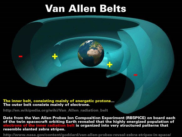
try one of these neon ligh tubes as standing wave indicator. There will be different Zebra-Effects (sequences of dark and light areas) which correspond to positions of nodes and antinodes over the coil.

My guess would be that a single tube would not work as well as the neons for showing this. That the tube would become conductive and have its own resonant frequencies for standing waves, but it could show a running zebra pattern as can be seen in some other videos. It would probably work if one places many small tubes in parallel with spacing and placed the coil on top of a bed of parallel tubes.

If anyone wants to try creating a 1/2 wavelength standing wave in a florescent tube then we might wonder if the frequency that wave appears indicates a wave velocity faster than c, about c, or much slower than c. I'd be surprised if we see faster than c velocity inside one though, its not going to be nearly as conductive as copper.

  • Liked by
  • Chris
  • Augenblick
Enjoykin2118 posted this 26 May 2018

Hi Zanzal

try one of these neon ligh tubes as standing wave indicator. There will be different Zebra-Effects (sequences of dark and light areas) which correspond to positions of nodes and antinodes over the coil.

Dont bias NST, they are auto biased.

Best wishes

Enjoykin


Chris posted this 26 May 2018

Hey Zanzal,

Fascinating, the Rotation of the globes in the plane of the EM Wave showing changes is absolutely fascinating. Obviously the Radiation is showing up as we would expect to see in an Antenna:


For me, this helps prove a lot of things I have been working on, suspecting and attempting to verbalise, but at the same time not fully grasping. I have tried to push the idea of thinking of Coils in resonance as an EM Wave:using the 1/4 and 1/2 Wavelength principles.

My Thread: Electromagnetic Waves, does cover a lot of stuff, and suggests Coils in resonance follow the same principles as Antenna's.

I find your experiments very valuable Zanzal

Thank You very much for sharing!.

   Chris

  • Liked by
  • Zanzal
  • Augenblick
Zanzal posted this 26 May 2018

Question: I am assuming your Neon Globes are all open circuit, essentially sitting in free space but in the proximity of the coil? There is no Electrical Connection?

Not with wires, but if you expand your idea of a circuit then yes they are part of the circuit drawing power from the coil even without wires. Really its just a matter of whether or not the voltage potential exceeds the neon voltage drop. So if the neon lights at 80V then it will need 80V of potential to be lit at all. Fall below this and nothing.

Also, what plane are they sitting reference to the Coil? Rotation the Neon Globes 90 Degrees, does this change the glow?

The angle is important. If they are oriented in a different direction they will light differently. They seem to work best with the capactive plate angled toward the coil but as you can see it may be a 45 degree angle or so and no issues. Both pictures they are each roughly the same linear distance from the coil and at approximately the same angle to the coil. I have them pushed up close to the coil to ensure that fact.

You can't have your hands anywhere near the coil (6-8 inches) though or you can't expect them to work right. Metal objects seem to act as reflectors with these setups same with the human body. Hands near the neons will cause visible lighting effects and touching the coil seems to prevent resonance, I already explored a lot of this before with the slayer exciter and it didn't prove all that interesting. This thing does an ok job of mapping out the field density though and when approaching or moving out of resonant frequency the bulbs will dim and the field will diminish in the same patterns as they appear.. So in the 1/2 resonance leaving resonance the outer neons will dim and turn off before the inner ones.. These things are not really surprising.

Would you mind upping a close-up of the Neon's

  • Liked by
  • Chris
  • Augenblick
Chris posted this 26 May 2018

Hey Zanzal,

Thanks for the update!

Question: I am assuming your Neon Globes are all open circuit, essentially sitting in free space but in the proximity of the coil? There is no Electrical Connection?

Also, what plane are they sitting reference to the Coil? Rotation the Neon Globes 90 Degrees, does this change the glow?

Would you mind upping a close-up of the Neon's

   Chris

  • Liked by
  • Zanzal
  • Augenblick
Zanzal posted this 26 May 2018

Am still thinking on this... What happens if you move the Primary into the centre as suggested by Enjoykin? Do you get the same pattern on the neons?

Some of the effects are there. I was able to get it to work by switching to a 2x3turn primary to boost the voltage up. It appears as a 1/4 wave resonance pattern at each end of the coil. Wavelength approximately 426m (4x106.5m) at 596.7kHz and its  wave velocity is about 0.85c. I would guess that this is a dipole antenna? 

If I join the two ends I no longer have 1/4 wave resonance but I can detect a standing wave at 1 wavelength of 213m using the center primary (it has to be mapped out with an Avramenko plug, but its there) and its resonant at 2MHz. So velocity is 1.42c. There is some consistency here. When we have a standing wave we measure a velocity greater than c, but we can have lit bulbs without a standing wave resonance pattern and its less than c.

If we assume that transverse emissions (radio waves) are present in the standing wave resonance than it may be they are the cause of the bulbs lighting. Tesla said that it was an important to minimize these emissions by using frequencies below 30kHz.

Chris posted this 25 May 2018

Hey Zanzal,

Fantastic Post!

Your experiment proves very valuable!

Am still thinking on this... What happens if you move the Primary into the centre as suggested by Enjoykin? Do you get the same pattern on the neons?

I have a feeling the pattern on the neons are Field related as you stated, but are showing Electric vs Magnetic rather than a Standing wave.

We know the Magnetic Field to be Orthogonal or at Right angles to the Electric Field, I am not sure how the Neon's are seeing such a difference in Potential, but I guess the fact that they are glowing shows that they are.

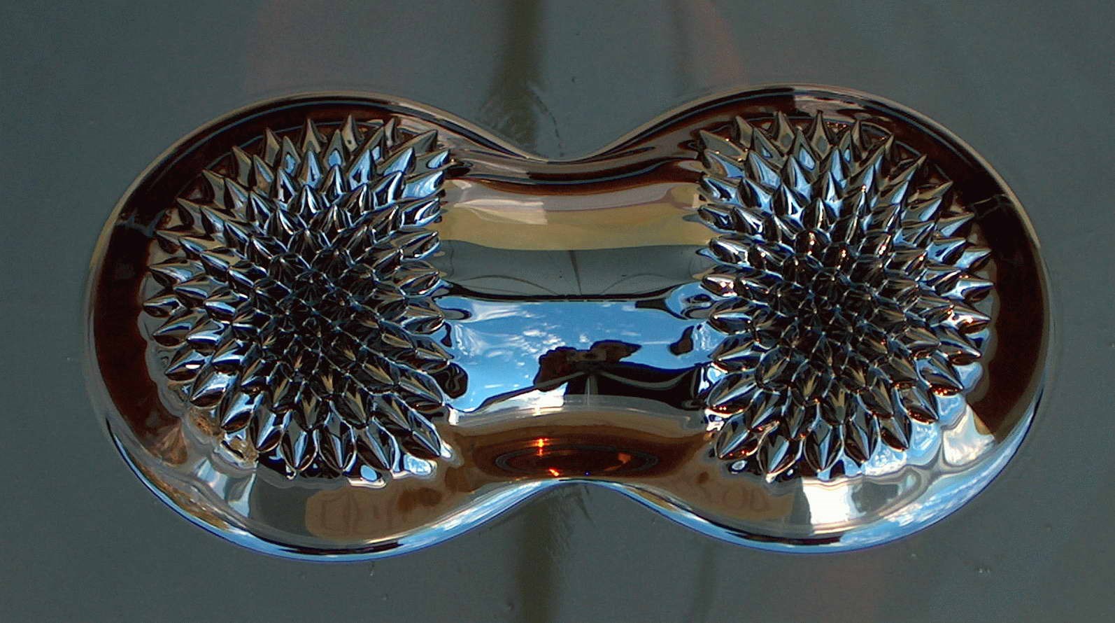
I personally believe the Neon's are showing the Gradient of the Electric Field around the Inductor:


We saw this, but opposite in the Ferro-Fluid:


My comment on the Standing Wave above, this I say with a broad conventional View, not taking into account my view of the Magnetic Field discussed further here: The Field Structure of Nature

I realise, this may be plainly obvious to some already, for others perhaps not.


When I was younger I took a college trig class. I saw all these strange functions, sin, cos, atan, tan, log and I could not understand how they worked so I asked my professor, and he told me I didn't need to know how they worked I just needed to memorize how they relate to each other and use them to solve problems. But I could not accept his advice at the time and I dropped the class. For me not knowing how they worked prevented me from seeing the big picture.


Well said! there is an infinite difference between knowing something and understanding something - Humanity is so lost! The memory of Knowledge and the Understanding of Knowledge are totally different things! This bothers me to no end!

Great post my friend!

   Chris


  • Liked by
  • Zanzal
  • Augenblick
Zanzal posted this 25 May 2018

Just a follow up note, that last post contained some speculation at the end, feel free to comment but I hope we don't get too hung up on that. I myself am not too concerned with how things work, and I don't want to get too attached to those silly ideas I wrote below.

  • Liked by
  • Chris
  • Augenblick
Zanzal posted this 25 May 2018

Currently I am still thinking, still imagining where is what at where in Time.

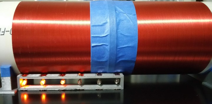
I'll draw you the circuit this weekend, but you'll be disappointed. There is no secret sauce in the circuit. The primary is the 5 turns of wire under the blue painters tape. The signal generator is connected to both leads of the primary coil. You can however, detach the signal generator ground lead and it will still work due to the single wire transfer effect (frequency will change a bit).

The secondary is the large air core inductor. I can add a top load, a bottom load, two grounds, two open ends, and mix and match these combinations. I can even connect the two ends together to form a shorted coil.  That is a slightly different case as a shorted coil should not have its secondary harmonic at a wavelength of one, but will still be resonant at 1/2 wavelength. In my case my coil will be resonant at 1030MHz +- 50kHz depending on the configuration.

When I was younger I took a college trig class. I saw all these strange functions, sin, cos, atan, tan, log and I could not understand how they worked so I asked my professor, and he told me I didn't need to know how they worked I just needed to memorize how they relate to each other and use them to solve problems. But I could not accept his advice at the time and I dropped the class. For me not knowing how they worked prevented me from seeing the big picture. In the end sin and cos are nothing but tools to solve a problem. It matters not how they work. Understanding those details may come later in an epiphany, but even if it doesn't you will still be able to use them to solve problems.

How do you explain the lighting pattern on the neon bulbs? Why are the two end bulbs dark?

This is how I see this: The voltage potential in the area by those dark bulbs is insufficient to reach the intensity needed to conduct current. The experiment does nothing to explain how the ones that do light up actually light up. It matters not how they light but we do know why some are lit and some are not. We can prove the light pattern conforms to a wave at 1/2 wave length just by visual observation. We know its a standing wave if the wave were not standing we'd expect to see somewhat even lighting pattern. And we know that a standing wave results from cavity resonance where the distance traveled is at multiples of 1/2 wavelength. The first resonant will always be 1/2 then. Waves can be reflected and waves can travel in loops around the conductor (inferred by the fact that a shorted secondary is still resonant). I think it helps if we consider these waves to be waves of oscillating potential and the conductor is maybe a wave guide.

So if that is the right way to think of it then seems to me what this experiment proves is that the voltage potential propagates faster than the speed of light, even if the actual measured voltage due to electron flow does not. Either that or I'm just visualizing it incorrectly. Time will tell.

  • Liked by
  • Augenblick
Jagau posted this 25 May 2018

Hello Zanzal
Excellent work, as you say it should not be afraid to experiment and share,

I forgot to say that the closer we get to 1 Mhz the closer we get to c * 1.5 and that's what you get


Bravo I follow your thread with interest
Jack

Chris posted this 25 May 2018

Hey Zanzal,

It looks really good! Thanks for sharing!

Taking the Electric Field and the Magnetic Field and observing both at the same time, in a wave I think has huge benefit wink 

You know, I still have trouble getting the whole picture, I do wish I grasped it better! Currently I am still thinking, still imagining where is what at where in Time.

For a Standing Wave, two wave must be travelling in opposite directions as you know. Other wise there is no Standing Wave.

Would you mind posting a simple schematic for my tired old brain?

Great work my friend!

   Chris

  • Liked by
  • Zanzal
  • Augenblick
Zanzal posted this 25 May 2018

I tried and I could not make this work, but, clearly it works! The Frequencies and running resonances are hard for an ammeter! At the time, semi-specialised equipment would have greatly helped but was un-affordable.

No worries Chris, my goal is to pursue the research and do the experiments myself and to simplify it for others. I hope that when I'm done it becomes very clear so that those who build OU devices can send their power anywhere in the world. To that end I will continuing sharing so that everyone has the opportunity to learn these things. I hope to get this down to a high school level - accessible to all.

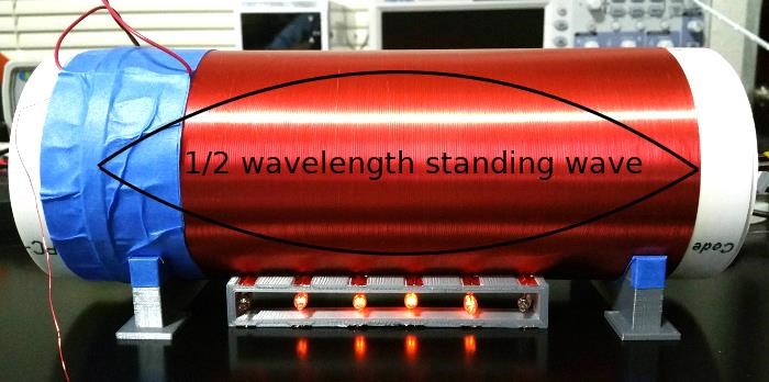
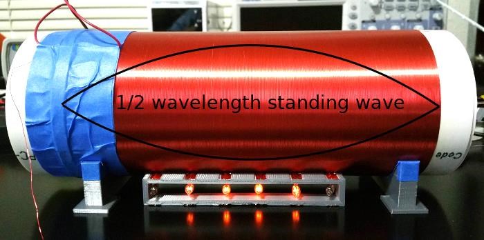
So I refined the experiment to better demonstrate longitudinal waves and In the process I also learned that my initial concepts of the wave were wrong. What I had envisioned was what would actually be called a 1/4 standing wave if such a thing could exist not a 1/2. Once I discovered my mistake I built a detector based on inspiration from perro555's electricians meter and Tesla's detector described in The True Wireless. My interpretation of Tesla's detector may be incorrect, but my results I think clearly demonstrate the idea better than I can describe them with words:

Wavelength is 426m (2x213) and frequency is 1.06MHz so wave velocity is around 1.5c. Detector shows wave is standing wave with 1/2 wavelength.

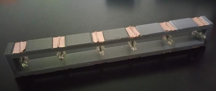
My detector is just a 3D printed piece of plastic with 6 neon bulbs spaced every 2cm, 1/4" copper tape is used as capacitance on both sides of each bulb and also to tape the neon bulb leads in place. Extremely simple. Center bulbs are lit demonstrating the standing wave at 1/2 wavelength. I'm going to consider this proven. 

Fun trivia: When reading older writings the term detector can often mean diode or rectifier. But Tesla's detector just looks like a strange light bulb. 

I'll attach the STL file to this post in case anyone wants to print one but I don't really recommend going out the way to do so. While this detector has its uses for visualizing the intensity of the field along the length of the coil, it has limitations mostly in that its really hard to get a good idea of intensity. Using an array of Avramenko plugs might be a better design since LED brightness seems to scale better.

The results seem conclusive to me, I can now move on to the more difficult aspect of this which is power transmission. More to come (might be a few weeks or more)...

Attached Files

  • Liked by
  • Chris
  • Augenblick
Zanzal posted this 21 May 2018

My very average calculations show this could still be in the Far Field, just something to think on:

Antenna Length or Diameter (D): 0.15 m
Frequency (f): 1.234 MHz
Wavelength: 242.94364506 m
Reactive Near Field Distance: 0.00231087 m
Radiating Near Field Distance: 0.00018523 m
Far Field (Greater than this distance): 0.00018523 m

I had considered this possibility as well, but it just occurred to me that the first resonant frequency for a transverse wave should be at 1/4 wavelength should it not? If that's true then the first resonant frequency would need to have been at ~416kHZ. That's based on 4x180 = c / f. I'll have to collect data on this. Should be able to reproduce this week. Thanks Chris, you've given me some ideas..

  • Liked by
  • Chris
  • Augenblick
Chris posted this 20 May 2018

Hey Guys,

I think debate is bringing differences, lets focus on facts and experiments!

I did a lot of research on Meyl Konstantin and his work many years ago:


I tried and I could not make this work, but, clearly it works! The Frequencies and running resonances are hard for an ammeter! At the time, semi-specialised equipment would have greatly helped but was un-affordable.

Perhaps these ideas should be looked at some more?

I believe focusing on hard fact will be much more beneficial.

   Chris

  • Liked by
  • Zanzal
  • Augenblick
Zanzal posted this 20 May 2018

One of Tesla's methods for excitation telluric currents by MFT secondary with two independent points earthed.

Good post Enjoykin. That is what Ming Cao is doing. His first ground is mains. His second ground is a cold water pipe. His primary is at one end his pickup coil used for measuring resonance is at the opposite end. He is not actually trying to transmit power through the ground, he is simply trying to measure the wavelength of the standing wave and using the usual equations he shows mathematically that the propagation speed is faster than c.

Enjoykin2118 posted this 20 May 2018

One of Tesla's methods for excitation telluric currents by MFT secondary with two independent points earthed.

Best regards

Enjoykin

Zanzal posted this 20 May 2018

His [Thomas Edison] method was inefficient in the extreme, for an immense ground had to be covered to get anything at all unless blind chance intervened and, at first, I was almost a sorry witness of his doings, knowing that just a little theory and calculation would have saved him 90 per cent of the labor. But he had a veritable contempt for book learning and mathematical knowledge, trusting himself entirely to his inventor's instinct and practical American sense. In view of this, the truly prodigious amount of his actual accomplishments is little short of a miracle. -Nikola Tesla

Enjoykin2118 posted this 20 May 2018

Zanzal

That Ming Cao's experimentis very primitive and has nothing common with Tesla's Magnifying Transmitter system nor with Tesla's longitudinal waves generation principle. Ming Cao's "secondary" is simply short-circuited coil with one common earth ground. I don't think he used two independently earth ground points with two highly conductive copper rods stucked in the ground..


  • Liked by
  • Chris
  • Augenblick
onepower posted this 20 May 2018

Chris

I believe you are correct on the output level and I commented because I have done similar experiments and know others who have as well. The secondary ground terminals can also be replaced with top loads and produce similar results.  

I believe we have two options:

1) The potential conducts faster than the speed of light in an ordinary copper wire. 

2) The potential does not always follow the path of conduction and can conduct over the wires.

Here is a good example...http://amasci.com/tesla/tmistk.html

It also begs the question, many say energy flows along the surface of a wire and yet here it is assumed that it must be bound to the conductor in order to get a result faster than C... so which is it?. It would seem to me this is a case of moving the goal posts in order to get the desired results.


Chris posted this 20 May 2018

Its a little hard to follow, the video is a little unclear.

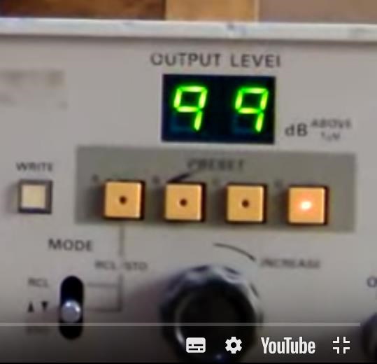
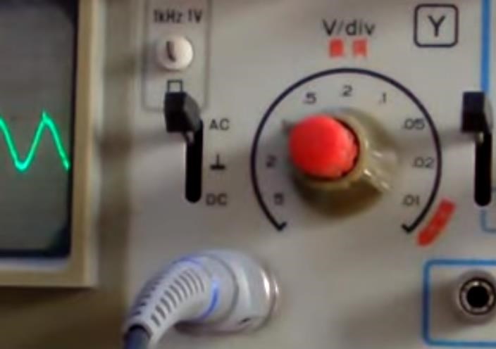
I believe the 99 on the Function Generator is in db, decibels and I believe this is 0.99, I may be wrong. This would give an output Voltage of 1.12V. 


I believe the Scope was set to either 0.01 Volts per division or 1 Volt per division. 


Please point out any mistakes I have made guys. Been a long day and my observations are a little rusty around the edges.

   Chris

  • Liked by
  • Zanzal
  • Augenblick
Chris posted this 20 May 2018

Hey Guys,

First up, I am still a novice when I talk antenna's, so what I say, I may not be right, its just my gut feeling.

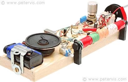
Coil Antennas are used for Far Field Transverse Waves, one example:

Ref: www.petervis.com/


I am not sure about the Video, perhaps there may be Longitudinal Waves there, perhaps Transverse Waves. If one were to roll out the Coils, 1.8M and if they were still in the same plane, would one get the same effect at the same distance, no, the Inductance and Distributed Capacitance would change of course.

I am still thinking on this, I will remain on the fence. To be perfectly honest, this area I am having and have had problems with for a long time.

My very average calculations show this could still be in the Far Field, just something to think on:

Antenna Length or Diameter (D): 0.15 m
Frequency (f): 1.234 MHz
Wavelength: 242.94364506 m
Reactive Near Field Distance: 0.00231087 m
Radiating Near Field Distance: 0.00018523 m
Far Field (Greater than this distance): 0.00018523 m

I was very hesitant posting this, this experiment has merit, it is worthy of further investigation! All I am saying, is it may be worth being a little reserved as to the result and drawing conclusions to early.

   Chris


P.S: is the scope only at 1V / div? I would guess the output voltage is not as high as it should be according to the Function Generator?


  • Liked by
  • Zanzal
  • Augenblick
onepower posted this 20 May 2018

Zanzal

Quote:"Actually on second thought, no I don't think the voltage he was working with was high enough to cause those problems you described, so I find it doubtful."

We could apply some perceptual reasoning and look at what we know.

He has a 2 turn primary which is the brown speaker wire and it has two parallel conductors. Note the size of the black alligator clip attached to said primary suggesting the 2 turn primary is around 1m in length. He tells us the secondary is 180m in length thus if the input was 12v the induced secondary voltage would be 2160v. However if you look to the right of the frequency display we see another display labelled output level which reads 99. If it is 99v the secondary induced voltage is now over 17,000v. So with the high induced voltage, a high frequency near 1.2Mhz and the large dielectric effect due to the coil coating we have big trouble. More so when using standard 300v max, 1X/10X oscilloscope probes.

He also mentions both of the secondary terminals are connected to ground... in what way are they connected to ground?. Does he understand a supposed high resistance between the two grounds is relative?. That is, there is almost no resistance when the high potential can travel as a surface wave over the ground. I have seen much scientific literature and performed experiments which prove as much and water or ground offer no more resistance than a copper conductor at high voltage. We also know high voltage transmission lines only require one conductor and two ground points.

The devil is always in the details and Ming would seem to have made many false assumptions in my opinion. What I can say is that when you see something really extraordinary you will know it.

  • Liked by
  • Chris
  • Augenblick
Chris posted this 20 May 2018

@Zanzal - Awesome Thread.

   Chris

  • Liked by
  • Augenblick
Zanzal posted this 20 May 2018

Could be... Will have to experiment to know for sure. If I am understanding it correctly, the experiment I proposed should address the assumption he made that his wavelength is 2 times the length of the secondary. His calculations are based on the equation wavelength = wave velocity / frequency. The text book method would simply fix the wave velocity at c and not even entertain the idea that it could be greater than that.

Actually on second thought, no I don't think the voltage he was working with was high enough to cause those problems you described, so I find it doubtful.

  • Liked by
  • Chris
  • Augenblick
onepower posted this 20 May 2018

I believe Ming Cao made a common mistake due to a lack of experience also because he was following textbook theory and making assumptions. Did you spot his mistake?, first he assumed the speed of conduction was faster because he also assumed the potential must always follow the path of conduction in the wire. This is not true of a HV solenoid coil as shown and the potential will start moving over the surface of the coil as if it were a solid structure not unlike a copper pipe... jumping over the turns.

Do you see how a basic error in perception can skew our results?. Not to mention the fact he has covered the coil with a thick dielectric in which the electrical stress will start moving longitudinally along the dielectric jumping over the coil turns.

As such we should be very careful about what we think we are seeing and check our premise. In fact I have had current flow directly over the surface of a HV resistor bypassing it for no other reason than I touched it. The oil on my skin was transferred to the resistor at which point the resistor surface became the path of least resistance.  

HV and currents with a high rate of change follow a different set of rules than domestic electricity.

  • Liked by
  • Chris
  • Augenblick
Zanzal posted this 20 May 2018

Ming Cao in his video tells us that the wire in his secondary is 180 meters long. He excites the wire at one end with his primary coil and has a tertiary pickup coil at the opposite end. He scans for resonance using the pickup coil and locates the frequency using his scope. He then calculates the speed of his wave:

Wavelength = 360meters (Twice the length of his secondary of 180m length)
Resonant frequency = ~1.2MHz
Speed of wave = 432M m/s (C being ~300M m/s)

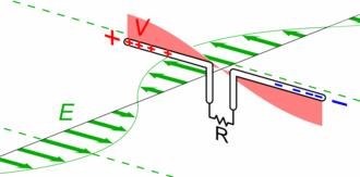
At first I was a little puzzled as to how he came to arrive at 360 meters for his wavelength, but then it dawned on me that this is based on a standing wave which has its greatest amplitude at 1/2 wavelength. I think maybe this can be visualized by drawing the wave over the coil like below:

Of course the wave is actually twisted in space around the coil along the wire, but that's not possible for me to draw.

Update 5/23: Attempts to replicate Ming Cao's experiment succeed easily, however, problems are noted. While my first configuration easily confirms his result, small modifications introduced new resonance points which when used with the same method indicate a velocity MUCH slower than c.

Update 5/24: I created a simple detector inspired by Tesla's detector and also a post by pero555 where he shows off his electricians meter. Wave shown was approximately 1.5c calculated at 1060MHz with a wavelength of 426 (2x213).

Zanzal posted this 19 May 2018

Dr. Hertz did not discover a new principle. He merely gave material support to hypothesis which had been long ago formulated. It was a perfectly well-established fact that a circuit, traversed by a periodic current, emitted some kind of space waves, but we were in ignorance as to their character. He apparently gave an experimental proof that they were transversal vibrations in the ether. Most people look upon this as his great accomplishment. To my mind it seems that his immortal merit was not so much in this as in the focusing of the investigators' attention on the processes taking place in the ambient medium. The Hertz-wave theory, by its fascinating hold on the imagination, has stifled creative effort in the wireless art and retarded it for twenty-five years. But, on the other hand, it is impossible to over-estimate the beneficial effects of the powerful stimulus it has given in many directions. -Nikola Tesla

Da Vinci was certain one day man would be able to fly, but it took another 400 years for him to be proved right. Tesla also was very certain that the adoption of Hertz theory's would one day prove to be a mistake and while that is probably not going to ever be the case one does certainly wonder what is it Tesla saw in his own system that made him so sure it was superior in every way. 

  • Liked by
  • Chris
  • Augenblick
Zanzal posted this 19 May 2018

The Hertz wave theory of wireless transmission may be kept up for a while, but I do not hesitate to say that in a short time it will be recognized as one of the most remarkable and inexplicable aberrations of the scientific mind which has ever been recorded in history. -Nikola Tesla

  • Liked by
  • Chris
  • Augenblick
Zanzal posted this 19 May 2018

There shall be wings! If the accomplishment be not for me, 'tis for some other. The spirit cannot die; and man, who shall know all and shall have wings. -Leonardo da Vinci

  • Liked by
  • Chris
  • Augenblick
We're Light Years Ahead!
Members Online:

No one online at the moment


What is a Scalar:

In physics, scalars are physical quantities that are unaffected by changes to a vector space basis. Scalars are often accompanied by units of measurement, as in "10 cm". Examples of scalar quantities are mass, distance, charge, volume, time, speed, and the magnitude of physical vectors in general.

You need to forget the Non-Sense that some spout with out knowing the actual Definition of the word Scalar! Some people talk absolute Bull Sh*t!

The pressure P in the formula P = pgh, pgh is a scalar that tells you the amount of this squashing force per unit area in a fluid.

A Scalar, having both direction and magnitude, can be anything! The Magnetic Field, a Charge moving, yet some Numb Nuts think it means Magic Science!

Message from God:

Hello my children. This is Yahweh, the one true Lord. You have found creation's secret. Now share it peacefully with the world.

Ref: Message from God written inside the Human Genome

God be in my head, and in my thinking.

God be in my eyes, and in my looking.

God be in my mouth, and in my speaking.

Oh, God be in my heart, and in my understanding.

Your Support:

More than anything else, your contributions to this forum are most important! We are trying to actively get all visitors involved, but we do only have a few main contributors, which are very much appreciated! If you would like to see more pages with more detailed experiments and answers, perhaps a contribution of another type maybe possible:

PayPal De-Platformed me!

They REFUSE to tell me why!

We now use Wise!

Donate
Use E-Mail: Chris at aboveunity.com

The content I am sharing is not only unique, but is changing the world as we know it! Please Support Us!

Thank You So Much!

Weeks High Earners:
The great Nikola Tesla:

Ere many generations pass, our machinery will be driven by a power obtainable at any point of the universe. This idea is not novel. Men have been led to it long ago by instinct or reason. It has been expressed in many ways, and in many places, in the history of old and new. We find it in the delightful myth of Antheus, who drives power from the earth; we find it among the subtle speculations of one of your splendid mathematicians, and in many hints and statements of thinkers of the present time. Throughout space there is energy. Is this energy static or kinetic? If static, our hopes are in vain; if kinetic - and this we know it is for certain - then it is a mere question of time when men will succeed in attaching their machinery to the very wheelwork of nature.

Experiments With Alternate Currents Of High Potential And High Frequency (February 1892).

Close