YoElMiCrO's Ferro-Magnetic Resonance

  • 6.1K Views
  • Last Post 18 November 2023
YoElMiCrO posted this 27 February 2020

Hi everyone.

Circuit to check ferro-resonance.
The two bulbs are 12V @ 35Watts, if you want you can do the experiment.
The mosfet can be an IRF3205, anyone with an Rds (on) whose value is at least
the value of the load between 10 so that Norton is negligible.
For example, if the bulb is 35W @ 12V, the minimum resistance of the mosfet in the state
on should be less than (12 ^ 2/35) /10=0.4 Ohm.
As the one I propose has 0.008 Ohm, it will more than meet that load.
With respect to the driver, anyone capable of delivering a peak current of 3A
It will be left over.
Here the images of the circuit and its tests.

The method of adjustment is as follows.
We apply a pulse of 2uS to the mosfet, at the beginning the 500 Ohm resistor in the gate to the minimum,
with a low frequency, say 100Hz.
We see the response in the waveform applied to the load, we adjust Ton so that
the answer begins at its maximum negative and at the end of Ton touch 0 Vdc.
Then we verify that in drain of the mosfet during the Toff cycle the answer is
ferro-resonant, this means that the first cycle of the sine function is not symmetric.
Then we raise the frequency while keeping Ton constant.

YoElMiCrO.


Order By: Standard | Newest | Votes
YoElMiCrO posted this 25 March 2020

Hi everyone.

I have the final hardware ready.
Modify the control stage so that we can all replicate.
It is made with discrete components and I think easy to get.
The core is an EI33/3C90, the common ones in computer SMPS and TL494.
Later two 556 timers that I think are easier to get.
Here the images of the hardware.

Control with verifying the correct mode.

As I commented before, when it is 100% I publish it in this tread.
Thank you in advance.
YoElMiCrO.

YoElMiCrO posted this 09 May 2020

Hello everyone.

This seems to be the end of the experiments.
Here is a photo of the collector that I made in 3D.


Some capture of the scope, in yellow the primary voltage
in mallow secondary voltaje.


The control circuit is not yet finished, the tests are carried out with the
the last photos of this post which has a PLL and two digitizer,
I call it Non-Lineal Electric Generator (NLEG).
The final idea is to close the loop and take energy from the rest.
I will keep you informed.

YoElMiCrO.

Thank you in advance.

YoElMiCrO posted this 23 March 2020

Hi everyone.

As I commented earlier, with the circuit I made I could
perform innumerable physical tests that were corroborating the hypotheses
varied that arose on the actual operation of the circuit with two TL494 from Akula.
After doing a lot of analysis this is the best approach.
I will try to explain its operation as simple as possible!
The circuit in question is that of the two TL494s, I think flashlight # 3.

It has a TL494 in free osc mode, frequency and duty cycle are controlled.
the duty controlled from pin 4 which controls the dead-time when configured
in push-pull mode, pin13 to Vref.
It is configured in common mode, since pin 13 at ground potential.
In this way we can control the duty 0 ~ 100%.
This free oscillator is key in its operation, but now we will see it.
The following TL494 is a Boost-Converter whose duty does not exceed 50%,
This is in charge of keeping its operation stable through the control loop,
which modifies the duty inversely proportional to the output voltage.

This is my point of view on the concept of operation.
This circuit involves two concepts, one that is already known and the other still under study.
The first one tries to have the least loss, (better efficiency) and it goes away that
reaching a maximum BH/2 magnetic energy is better to increase it cycle by cycle.
The second is about the negative region of ur.

It happens as follows ...
The free oscillator circuit causes increments of 100Gaus for example.
Your duty in question will be such that EdcTon = VfbToff and the stored energy
BH/2 will return to the input capacitor, this way the source will only have to
provide the energy of losses of the circuit and its consumption will be very low.
Now the Boost-Converter is participating.
It has a lower frequency such that its maximum duty (also controlled
from pin 4) fit the number of free oscillator pulses needed that
increase the energy discreetly until B is such that its ur is maximum.
As the two coils have the same phase, during the time that it is active
the primary with the highest number of turns (the Boost-Conveter), the one with the fewest turns will see a short
during the toff cycle and will not be able to release stored energy BH/2
because EdcTon is now unequal to VfbToff.
This causes the current to increase cycle by cycle, just as the Boost-Converter applies
Toff the short seen by the free oscillator is no longer, this causes all the
stored energy release, but remember that this oscillator is free.
During this Boost Toff time the tension in the free osc mosfet drain
it will be higher than Edc and its next cycles over saturate the core making it pass
by the negative slope of ur, in this way during the Toff time of this oscillator
free the flyback voltage peak (Vfb) in the drain will be of various magnitudes (So
protection in the mosfet drain) while the energy stored in the area lasts
left of the hysteresis (Br/Bs) until it is completely delivered to the
Input Load/Capacitor.
It is this energy that added to the stored BH/2 causes the AU.
Now we have an energy that comes from the ferrite itself + the one that we previously stored
cycle by cycle.
This explains the reason for a gap in the ferrite.

I will make a final circuit with discrete ICs and when it is 100% functional
I'll post it so all can replicate it.

I hope serve something.
Thank you in advance.

YoElMiCrO.

Chris posted this 25 March 2020

Very nice! Awesome Work YoElMiCrO!

Thank You for sharing!

I am so pleased we are all working together! We can only do this together! We are all filled with the same colored blood, DNA is the same species, so we have to stick together, work together! Work for each other and all of our futures!

Best wishes,

   Chris

YoElMiCrO posted this 26 June 2020

Hi all.

Due to lack of time I have delayed publishing my results,
but little by little I will!
So I will keep you posted.
I think I understand what is the common phenomenon associated
to all the FE devices that we see on the network.
All circuits are related in one way or
another to Nikola Tesla's Harpin and its way of working.
It is this circuit that is capable of opening that window to extraction
energy, because the explanation is extensive I will publish it here.
There is another much more complex method, this is layers of opening
no longer a window but a door to the extraction of energy.
This method is much more complex to understand but not impossible
and credit to it goes to Floyd Sweet.
From my point of view he achieve a Bose-Einstein condensate at TA.
In other words, it achieved the fifth state of matter through its PM and at room temperature.
I will also publish it in the same tread for being much more extensive than the previous one.

Thank you in advance.

YoElMiCrO.

YoElMiCrO posted this 15 July 2020

Hi all.

Do not despair, this road is long, but we have already
traveled more than 70%.
You have to be cautious when affirming AU publicly,
it is clear why, not everyone believes it is possible, most
attacks those who acclaim it, even if it is free and publishing
all the details of its construction as happened to Chris at OU.com.


I can assure you that I have carried out many experiments
in an effort to understand only one phenomenon, in which I believe
which are based on all the circuits that we currently see
In the net.
Whenever time permits, I carry out an experiment
to understand a hypothesis that occurs to me, to see if it is
true or false.
Even Chris's POCs make use of this phenomenon.
Today I can say that it is the leakage inductance that
one way or another interacts with the medium, that's why
that we see air-wound systems, while
others use ferromagnetic core.
To this we must add that it only happens when the current
overtakes the tension by 90 degrees.
If we use a ferromagnetic core, a solution
is to create ferro-resonance, another one that Chris implemented.
If, on the contrary, it is an air winding, a discharge
capacitive to generate the necessary current peak.
If the system is hybrid, it has a ferromagnetic core
working in ferro-resonant mode, so that in this way
an abrupt current peak reaches the primary coil.
This is how Nikola Tesla's Harpin works in broad strokes.

There are other methods ...
The one with N.E Zaev, (DC / MC)> 1
That of Konstantin Meyl, Nikola Tesla transmitting and longitudinal waves.
And the most advanced of all from my point of view,
worth studying in depth.
Floyd Sweeet's, Intrinsic One-Dimensional Coherence in PM.

@Atti.
Thanks for giving you to carry out experiments, I already had you.
I have many of you in this great forum!
As an example…
Chris, Vidura, Jagau, Fighter, cd_sharp, wistiti, Zanzal, to name a few.
And again, thanks to everyone.

@Chris.
It's not fair that they attack you when you share without
ask for nothing in return, sorry, that's the way society is when you don't see beyond!

Thank you all in advance.

YoElMiCrO.

Jagau posted this 15 July 2020

Thank you YoElMiCrO

 These are deep thoughts and you have very well summarize the situation on the forums.

I also appreciate your presence and those of others too, we really have a nice forum.

Jagau

Chris posted this 15 July 2020

My Friends, You are all awesome!

I have the deepest respect for you all!

@Atti, regarding this sentence:

I do not understand this sentence. If you would like to express it differently. The google compiler is behaving strangely.


I am sorry!

What I mean is: Basic rules apply. Basic Rules cant be changed.

My admiration for the awesome people here with us! I have such respect for you all! Thank You so much for the awesome you all bring here!

Best wishes, stay safe and well My Friends,

   Chris

Jagau posted this 27 February 2020

Hi yo
excellent experiment to replicate, which I will do.


So you have to achieve this asymmetry by adjusting the Ton that you adjust by the variable resistance on the gate of the mosfet. After that, you can change the frequency only when you reach the asymmetric point, is that it?

Jagau

Jagau posted this 28 February 2020

yes Vidura
Same effect, you were faster than me


Well done


Jagau

Vidura posted this 28 February 2020

Friends,

If I may for a clearer understanding these images. this is the theory from Yoelmicro, what he explained to me:

below we see a  nearly quadratic hysteresis loop :

this means that the magnetic flux decreases very little from saturation to remanence. This is a requirement of the material to get the effect. in the following image we see the relative permeability for a given material, with it's negative slope between μmax and μsat.

We have to aim to maintain the working point of the inductor-transformer in the negative slope. the steeper the falling curve the greater the amplification factor. This causes that when the applied field decreases, the permeability increases, just the other way around than in the linear region. this make the hysteresis loop circulate the other way around, it's like a time reversal, and thus can pump energy from the aether.

generally a current regulated switching is required for stable operation.

Vidura


YoElMiCrO posted this 02 March 2020

Hi everyone.

@Jagau.


If you look at the circuit it causes it to work only in the first quadrant.
The variable resistor sets the operating point so that the current is always positive.
I just wanted to see if Ur's negative behavior is real and compare it to the behavior of the Leo Esaki (Tunel) diode.
Looking at this image will be clearer.

The relationship between Br/Bs also dictates the negative slope of a
given material The closer to the unit the greater the slope
and therefore greater amplification thereof.

Regarding the experiment you did, I can say the following.
If you look after turning off the Sw, the drain voltage of the mosfet rises sharply,
but the time that remains is extremely small.
That indicates that now the series inductance is very low and is discharged through
of that new time constant SQR(LC)=t, during this new semi cycle
the mosfet's parasitic diode enters conduction returning energy to the capacitor
of the source and the time that remains negative increases because now you will have to
leave the first quadrant to the third and saturate the nucleus in that quadrant.
And so while there is energy left in the capacitor.
Explain why so low current.
Good demonstration of nonlinearity in inductance.
Thank you.

YoElMiCrO.


Jagau posted this 24 March 2020

Hi yo
Very interesting, this is the major part of AU

It is this energy that added to the stored BH/2 causes the AU.
Now we have an energy that comes from the ferrite itself + the one that we previously stored
cycle by cycle


yes it serve and and I appreciate your point of view thank"s

Jagau

Jagau posted this 27 March 2020

Hi yo
When you talk about the circuit with 2 TL494 is that what you mean?

  If we look at the parthened output coil, it polarizes the center with the positive and activates the 2 mosfets on the negative side with two frequencies in push pull mode, i think so it is the best solution.

Jagau

YoElMiCrO posted this 29 March 2020

Hi everyone.

@Chris.

The circuit that Jagau exposes is the one I am referring to.
It is this circuit that I study to separate the events on which it is based.
So I think that as a schematic reference is fine.
I must say that it has errors, but as a reference it is fine.

@Zanzal.

I thank you for this topic here it is the real key to UA.
I already understood 100% what is happening, also other circuits
previously they claim AU works the same way.
As soon as possible I will write a document and send it to Vidura
for him to translate it from Spanish to English, nothing better than a human being.
Thank you Vidura for giving you.

YoElMiCrO.

Chris posted this 30 March 2020

My Friends,

You know, after reviewing the video from A Valon:


I think I may understand more what YoElMiCrO is meaning!


See the video Duty is set to: 25% and 50% respectively, same as the Grandfather Schematic. Two PWM's to two Mosfets same also! The Similarity's are too close!

On the other forums, I have spent so long fighting, debating and being attacked, I had to stick to my guns with such conviction, I may have over-looked a few other things.

We are dealing with two slightly different things here. Perhaps another way to get to the same end result. Still, lets see, Voltage and Current wise, lets see what YoElMiCrO finds as to these fundamental situations.


The voltage appears to be increased, by fundamental change in Inductance, which we know changes with the Magnetic Field, we know we need the Voltage up, this appears to be another way to do it, rather than delayed Conduction.

Lets see if the Currents via the Right Hand Grip Rule oppose during the "Generational" Phase?

Going back, reading, I owe an apology to Zanzal, sorry old friend! If I was not open enough to your new ideas. I should not have closed my mind to new ideas on getting the Voltage up, I am sorry!

Best wishes,

   Chris

YoElMiCrO posted this 06 April 2020

Hi everyone.

@Chris.

I want to tell you that for me all your videos are spectacular.
Also your ideas/theories /analysis/etc, as I said earlier
we all learn from everyone.
I apologize for just posting the waveforms without at least
say what it is about, I think with this image you will be able to understand better
what it is really referring to.

I must say that the DUT is just a common transformer, only that
It is made in an unconventional way and can be air core.
The phase difference seen by the generator source is 90 degrees
between voltage/current, while the phase difference at its output is 0.
In this way it produces useful work in its output while we spend
of the generator only the intersected E/I area and the latter
polarizes the medium in such a way that it increases the field E, being
their ratio of turns 1:1.
Something that for my knowledge should not happen under any circumstances.
But to understand something you need patience, a lot of it!
As you say, it is a resonance situation that does not obey conventional TM.
Still under study.

Thank you in advance.

YoElMiCrO.

Chris posted this 06 April 2020

Hey YoElMiCrO,

Thank You! I really appreciate your very kind words! I am very flattered!

No need to apologise. wink

Like you, I learn lots from others also. Experiment is one of the main areas I focus, and I try to gain understanding from there. All here on this forum, all are extremely intelligent and I very much appreciate all here!

I agree, on the Output, under Resistive Load Conditions, the Voltage and Current can be almost purely in phase. Real power.

Thank You for sharing your work YoElMiCrO! I see much clearer now thank you for the explanation.

Best wishes,

   Chris


YoElMiCrO posted this 14 May 2020

Hello everyone.

@Fighter.

Yes, more or less calculate the losses associated with each circuit.
I still do not succeed, but it is a matter of analysis / solutions.
The circuit I test with contains a PLL,
power circuit, these consume about 30mA @ 12Vdc and
It has a buck converter with an efficiency between 75/85%.
This type of electricity is rare, I have to do more tests.
The PLL is a CD4046 operating with phase difference 0.
The pulse amplifier is a 30A peak IXDI630MCI power driver,
the buck converter an AP1501 and a double power diode MOSPEC F12C20C.
I have not had time to continue with it, but this end I resume.
I will let you know how the idea evolves.

Thank you in advance.

YoElMiCrO.

YoElMiCrO posted this 14 May 2020

Hello everyone.

@Chris

Note the similarity of the experiments.


In the case of Floyd Sweet the magnets set the static operating point
while the inductor modulates the variation with a small current
of magnetic permeability.
In my case the static point is defined by the current flowing through the
same inductor while the alternating signal applied to the input modulates
said current.
It was this test that proved to Floyd Sweet that the nature of matter
It is different from how we imagine it, from that experiment it came directly
how to perform your SQM.

Thank you in advance.

YoElMiCrO.

Chris posted this 14 May 2020

Hi YoElMiCrO,

I agree, I viewed this image for a long time, not realising its importance, then my experiment came full circle and I ended up proving the importance in this diagram!

It is super Important, and for many they may not see how important, the best way I found to explain it is in the form of Energy "Generation".

At Resonance, what one Wire Carry's, the other Wire must also Carry, but the opposite way! Then that's a 2 for one scenario. Above Unity results.

Thank You for sharing YoElMiCrO! I appreciate your work!

Best wishes, stay safe and well,

   Chris

Atti posted this 22 June 2020

I definitely need to repeat this arrangement.

Implementation of Jagau:


Similarity:


YoElMiCrO posted this 23 June 2020

Hello Atti

If you want I tell you how the circuit works
that you published.
I find myself finishing some definitive experiments,
the objective is the same, the ultimate over unity.

Thank you in advance

YoElMiCrO.

Atti posted this 24 June 2020

Hi.

YoELMiCrO

It would be great if you could explain. I don’t have time to deal with the topics yet. All my stuff is in boxes. But I will have time to think about the theory. Thanks in advance.

Jagau.

This circuit is an ignition system. But it is very energy efficient. Similar to the proposed circuit.

http://zsiguli.hu/cikk/55


Atti.

Chris posted this 27 June 2020

Hey YoElMiCrO,

Cant wait to see your progress! Great to see more info on your progress!

Best wishes, stay safe and well My Friend,

   Chris

YoElMiCrO posted this 13 July 2020

Hello Atti.

The transformer inside NLEG is a wound toroid and this
inside a 90 degree air core solenoid, then the whole assembly
between two radial micro-wave oven magnets in attractive mode.
I think this image is more illuminating ...

The reason for using this type of magnet is that its magnetization is
almost homogeneous, I tell you that I could not finish the experiment
still for lack of time, but with the search the true nature of
the matter that we observe around us.
There is still work time in it, because according to my hypothesis on the subject
this experiment should be able to open not a door but
a gate to the world of energy that is at atomic levels.
If we think a little ...
There has to be an entity that provides energy to the atoms to
let them stay in motion forever if in any way
we managed to extract energy from the atoms this will have to contribute more
energy in order to keep moving these atoms.
This experiment to work depends on another development that
It is not completely finished yet, but little by little
it takes shape / functionality.
As soon as I see it working I will publish it with all the details
so they can replicate it, once done by some more
we make it public, so no one can tell us who we are
crazy people who believe in the fantasy of free energy.

Thank you in advance.

YoElMiCrO.

Jagau posted this 26 July 2020

Ok thanks Yo
This is what I wanted to be sure of.

For my part I use a Pot core with this formula that I am sure you know and about which I had already shared the info. However, you must know the inductance factor of your ferrite to use it


I have finished my work I resume my experiments where I had left

Thank you

Jagau

Jagau posted this 27 February 2020

Yes, I know that the switching speed, rise time + many other things, of the gate of the mosfet is determined by the gate resistance of the mosfet.

It was for this question, that I did not understand in your explanation given that channel 1 was to stay at 7khz as in your scope shot:


  we adjust Ton so that the answer begins at its maximum negative and at the end of Ton touch 0 Vdc

Thanks for the explanation


jagau

Jagau posted this 27 February 2020

Hi yo
I will build the circuit so we can join in our ideas.

Miller capacity , yes maybe. To prevent self turn-on  we have to prevent it?

One thing that I understood well with the ferrro-resonance it is very unexpected and it is triggered with a variation in voltage, as at the beginning of the thread, non linear resonance and ferro-resonance are add up in certain case.

Jagau

YoElMiCrO posted this 27 February 2020

Hi everyone.

@Jagau.

I find the idea of joining forces spectacular.
When I talk about the miller effect it is to use it as a capacity coupled to the circuit.
For example…
The capacity that the driver sees from the gate is:
Ct = Ciss + [Crss (1+ (Vds / Vg))]
One way to verify the effect of ferro-resonance is this:


What we do is download Cp through Sw then turn it off, now
as the voltage of Cp = 0 and if the value is large enough, it will keep
the voltage at 0V in the drain while growing di / dt to the point where the core saturates.
At that point the current is ahead of the voltage and the voltage in Cp will increase abruptly.
As in the following image.

The following oscillations are due to the fact that now Vcp-Edc is not 0 and will take the core out
of saturation until reaching the 3rd quadrant saturating it again and thus the following oscillations.
If you look while the tension falls, the time increases.

Thanks in advance.
YoElMiCrO.

Jagau posted this 28 February 2020

Yes very interesting to see the third quadrant YO
We immediately see an increase in time and thereafter the oscillation with longer time.

 Even that we managed to see almost a fourth goes up in the last part. Well done.

It's the simplest things that are the most explicit

Jagau

Vidura posted this 28 February 2020

Hey Friends, I did a short test of the circuit, with a CF139 core, the indian cosmoferrite is a cheap material, which has almost cuadratic hysteresis.
I cant do math measurements with my scope, but it looks promising, the effect is there:

the core becomes very noisy, unless it is pressed together with force.

regards VIDURA.

Vidura posted this 28 February 2020

Jagau, If you look at the second graph you can see that the relative permeability in the linear region increase from mu init to mu max. This region is used in conventional EE. Then from mu max. to mu sat. There's the negative slope. When the external field continue increasing, the permeability falls. Now at or near saturation we switch off the external field and the flux in the core start decreasing, while the permeability is now increasing, just the opposite way as in the linear region. Then we let it decrease, but only until reaching mu max. Then we energize the input again, starting the next cycle. Due to the cuadratic hysteresis we have to apply only a small amount of input power to bring the core again into the saturation region, less than the energy which can be extracted during the work cycle. I hope this helps for clarifying. Vidura.

Chris posted this 28 February 2020

Hey Guys,

@YoElMiCrO - Is this your theory? Do we understand this correctly?

The BH Curve, or the Hysteresis Curve is typically an Alternating Current Concept, the Magnetic Field pushes through a full cycle. We know the Magnetic Field is Current I through N Turns, which is M.M.F. There are Losses just in the BH Curve without loading the Transformer.

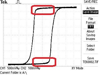
Of course, if the BH Curve is Non-Linear. B is Flux in Gauss, and H is Strength, so this Graph is Density vs Strength:


The Knee of the BH Curve, marked as b and e, is where we see the most Non-Linearity, but what is Non Linear? The Inductance of the Coil is lost at saturation, so this point is where the Coil is moving into Non Inductive and Inductive again. This is a material Effect, the Core itself is moving in and out of saturation at the knee, which is marked as b and e.


Some time ago, I published a document: What's it going to take to get OU? in that paper I gave some examples of this Inductance change and what it would mean achieving the Energy Gain. I looked at this from the point of Energy Stored in an inductor:  0.5 LI2

Looking back, I got my math wrong, squaring the Inductance, not the Current. However, a simple review:

  • L = 2.
  • I = 3.

We get: 0.5 x 2 x 32 = 9.


  • L = 7.
  • I = 3.

We get: 0.5 x 7 x 32 = 31.5.


The truth of the matter is, I does not stay constant, as L changes, I is forced to change also. So my math is not valid and does not take into account these changes. Of course, the definition of Inductance defines how Current travels through an Inductor. So more work is required in this area.

To make the Inductance change, then the Knee is where one should work:


One Coil getting you up to the "Turnaround Point", where a normal transformer is at maximum Magnetising force, and the other Coil pushing up over the knee and back again. Of Course this down hill is where one may see an energy gain.

@YoElMiCrO - Is this your theory?

Just so we are clear, my work is different from this, although there must be an opposition, I believe from Core to Output Coil is the mechanism. Energy must come from a Source, it cant just appear from fresh air. So a Pumping of sorts must occur.

Thank You Guys for sharing your work! I think there is a great deal that can be learned here. If we can all get on the same path here, then big steps forward could be made!

Best wishes,

   Chris

Vidura posted this 29 February 2020

Hey Friends,

It is indeed a very interesting theory. I believe that there has arise some confusion regarding the BH loop. We will see If Yoelmicro can clarify. But if I understood correctly, the theory and the related energy gain is only related to the non linearity of PERMEABILITY. The BH loop, which is actually the AC response of a given core, was only mentioned to point toward a specific property of some core materials, which are required to make benefit of the effect. That is that the relationship between Bsat and Br should be close to 1. So lets see what Yoelmicro has to say, he is actually the transformer expert, which I think is of great benefit for the forum community .

Vidura


YoElMiCrO posted this 29 February 2020

Hi everyone.
I will try to explain what I understand is happening, I have to say that it is more complex
that this approach, but more than enough.

@ Chris.

Yes, it is like that.
With regard to the hysteresis curve it is merely illustrative.
Going deeper into this we can define two areas within the first quadrant.
The area between Br / Bs is solely responsible for storage
of energy, that is why in the Flybak topologies a gap is necessary, because this
Increase the ratio Br / Bs.
And the area within the hysteresis loop, this represents the quality of said material,
It is directly related to the losses of this.
I think an image says more than words:

This is the first circuit I designed to study the phenomenon:

Looking at the material / core datasheet we take the value of H such that it is found
approximately 2Bsat from the first quadrant, after the core we get
the value of the effective magnetic length.
With these values ​​and using the Biot-Sabart law we calculate the number of
turns for that H obtained.

It would be as follows ...

N = (H * le) / (0.4 * Pi * I)

Where:

H = Magnetizing force in oersted (Oe).
I = Current in amper
le = Effective magnetic length in centimeters
N = Number of turns.

The circuit current variation is approximately between 100mA and 2A,
margin more than safe for the TDA2050.
Ideally, apply on 1A and calculate the number of turns using the formula above.
Then we apply at the input a sine function with frequencies between
1Hz ~ 20KHz, we will start with a low amplitude, say 100mV while
We look for a maximum on your way out.
Once that maximum is found we can vary the input amplitude.
Not all materials work, the best are as previously commented
those that the Br / Bs ratio is close to the unit.
These can be of Amorphous, Nanocrystalline or any other type with said characteristic.

@Jagau

If we start thinking ...
Within a deep saturation Ur = Uo and as we know the inductance
related to the solenoid that forms the inductor decreases to the point that now
its value is equal to if it had no core, in this way we can say
that virtually the core is in a vacuum.
During the non-active cycle the core will return virtually again, only that it is
You see that entity will be responsible for your return.
I think it is permeability that is capable of acting as an intermediary in the process
and the inductor would be the collector
I currently believe that E / H are independent and natural entities,
however, as an action / reaction one evokes the other.

Vidura posted this 10 March 2020

Hey Friends.
Let me remind you that in this thread Yoelmicro has shared a really very valuable theory, it can be easily tested by replicating the simple circuits. It is particulary useful as it allows us to understand the mode how the excess energy is tapped into the device, what are the required parameters and the properties of the magnetic materials to make it work. there are the formulas to calculate the working point of the inductor, and a test circuit to find the best working point, static and dynamic. Now it is up to us , to grasp it or leave it.

I really would encourage all following to do some testing on this, also think about how this data could fit into the particular device which you are working on actually. You might find that we can progress in huge steps if our knowledge becomes more complete.

I wish success for all of you,

regards Vidura.

Jagau posted this 10 March 2020

Hi yo
I'm trying to reproduce your demo circuit with the attached circuit
who is named '' Hysteresis measuring arrangement with a digital oscilloscope ''

for those interested there is also a circuit on the same site for analog oscilloscopes and other circuit.

https://meettechniek.info/passive/magnetic-hysteresis.html

Jagau

Chris posted this 12 March 2020

Thanks for sharing YoElMiCrO!

I am super happy others are working on this! Although there might be differences, I think in the end, we will find many similarity's also.

Some time back, we did cover the Knee of the BH Curve in the thread: Non-Linear Inductance


I believe  YoElMiCrO has taken this to the next level! Applying the Theory and the Circuitry and finding there is more to this! Proving what I was sharing as incomplete, which it is and I knew it. I am very happy to have such a great mind here with us! Thank You YoElMiCrO for becoming part of our team and sharing your expertise!

I had the steepest, most difficult learning Curve, and I try to always say "I am learning too", so others can see I may not always be right.

Although this tech is slightly different from my main technology I am sharing, Coil to Coil Interactions, I believe there must be a Core to Coil Interaction here. This action and Interaction pair must do the same thing, the Inductance Changes with the Magnetic Field, its not hard to see the Magnetic Field Change here. At its base level, this is Non-Linear Inductance.

Best wishes,

   Chris

YoElMiCrO posted this 13 March 2020

Hi everyone.

@Chris.

Thanks for this great forum, we all learn from everyone.
I think nobody has complete knowledge, most of the time what
we are not able to see others do it and thanks to that they expose it
We advance in this great task of AU.
Again thanks for sharing.

@Jagau.

No, the circuit is not on the NET.
I designed it just to start evaluating if it's how I theorize that
the circuit that owns two Akula TL494s works.
It is not the final circuit, use a PIC for calculation problems,
so I can solve the possible operating points.
Anyway here it is.

Thank you all in advance.
YoElMiCrO

Vidura posted this 29 March 2020

Hello Friends, As it seems that the version of Yoelmicro's circuit which uses the PIC microcontroller is performing better, I thought to put this link of a low-cost pic programmer for those who want to replicate: https://www.microchip.com/Developmenttools/ProductDetails/PG164100 The regular price is 15$ , now until 31of march it is 50% off. Regards Vidura.

YoElMiCrO posted this 15 April 2020

Hello Chris.

I've been a little busy with work.
But I have been able to carry out several experiments that corroborate AU.
In the shortest possible time I publish what I found, as well as
the circuit to replicate.
Sorry for the delay.

Thank you in advance.

YoElMiCrO.

Jagau posted this 22 June 2020

Hi atti
I took Yo's schematic to do this scope shot


For your help

Jagau

Atti posted this 14 July 2020

Hi YoElMiCrO.

I would like to thank you for the opportunity to learn about the theory so far. Once we know the details of the further hypothesis, I will contribute to the reproduction in every way.

Atti.

Chris posted this 14 July 2020

Hey Atti,

Some members have put a lot of work into this, and some of these members may be hesitant to share all they know. I understand, showing all one has learned can be more than a can of worms for many people. It is very hard to deal with the publicity especially when that publicity can be negative as I have seen again on ou.com.

Of course I don't believe anyone here would behave like that!

I think it is important to understand why some are hesitant to share! I don't blame them!

Best wishes, stay safe and well My Friends,

   Chris

YoElMiCrO posted this 19 July 2020

Hi all.

@Chris.

No problem with transferring it to Tier I, you can do it whenever you want,
the idea is always the same, to share the work, that way
among all users of this great forum can contribute their
ideas, experiments, etc.

I think we will soon have a new flashlight here at aboveunity.com, the flashlight that
it really works for everyone.

Note:I had to edit the last paragraph, because the translator put the sentences completely wrong,
I will have to leave the copy and paste and read carefully what he put in English

Thank you in advance.

YoElMiCrO.

YoElMiCrO posted this 26 July 2020

Hi all.

@Jagau

It's easy from where the square root of two derives,
but I think it goes without saying.
If the inductances share the same core
and one of them has to be twice the other then
the number of turns of the largest will be the turns
of the small by the square root of two.

Thank you all in advance.

YoElMiCrO.

Jagau posted this 10 August 2020

Hi Yo
I didn't forget you, just missed of time.
Yes your circuit produced a double pulse see scope shot at 100khz


N1= 100t

N2=50t

Resonant freq is 1.25mhz but a perfect sinus

Hi Chris


we have the same thing with a single coil with a second one we have a second pulse.

Jagau

YoElMiCrO posted this 16 August 2020

Hi all.

I've been busy lately
but I have had time to continue with the experiments.
I don't think there is much left to achieve something real
to prove once and for all that it is not a
crazy dream about AU.
I'm watching uploading videos about the experiments
to YouTube, so more conclusions can be drawn, those
that you do not realize by yourself, that is the idea of this
great forum.

Thank you all in advance.

YoElMiCrO

Vidura posted this 27 February 2020

Hey Jagau,

I think the Ton has to be adjusted by the signal source, and the 500ohm resistor has the function to control the rise time of the switch.

please correct me if im wrong Yoelmicro.

Vidura.

We're Light Years Ahead!
Members Online:

No one online at the moment


What is a Scalar:

In physics, scalars are physical quantities that are unaffected by changes to a vector space basis. Scalars are often accompanied by units of measurement, as in "10 cm". Examples of scalar quantities are mass, distance, charge, volume, time, speed, and the magnitude of physical vectors in general.

You need to forget the Non-Sense that some spout with out knowing the actual Definition of the word Scalar! Some people talk absolute Bull Sh*t!

The pressure P in the formula P = pgh, pgh is a scalar that tells you the amount of this squashing force per unit area in a fluid.

A Scalar, having both direction and magnitude, can be anything! The Magnetic Field, a Charge moving, yet some Numb Nuts think it means Magic Science!

Message from God:

Hello my children. This is Yahweh, the one true Lord. You have found creation's secret. Now share it peacefully with the world.

Ref: Message from God written inside the Human Genome

God be in my head, and in my thinking.

God be in my eyes, and in my looking.

God be in my mouth, and in my speaking.

Oh, God be in my heart, and in my understanding.

Your Support:

More than anything else, your contributions to this forum are most important! We are trying to actively get all visitors involved, but we do only have a few main contributors, which are very much appreciated! If you would like to see more pages with more detailed experiments and answers, perhaps a contribution of another type maybe possible:

PayPal De-Platformed me!

They REFUSE to tell me why!

We now use Wise!

Donate
Use E-Mail: Chris at aboveunity.com

The content I am sharing is not only unique, but is changing the world as we know it! Please Support Us!

Thank You So Much!

Weeks High Earners:
The great Nikola Tesla:

Ere many generations pass, our machinery will be driven by a power obtainable at any point of the universe. This idea is not novel. Men have been led to it long ago by instinct or reason. It has been expressed in many ways, and in many places, in the history of old and new. We find it in the delightful myth of Antheus, who drives power from the earth; we find it among the subtle speculations of one of your splendid mathematicians, and in many hints and statements of thinkers of the present time. Throughout space there is energy. Is this energy static or kinetic? If static, our hopes are in vain; if kinetic - and this we know it is for certain - then it is a mere question of time when men will succeed in attaching their machinery to the very wheelwork of nature.

Experiments With Alternate Currents Of High Potential And High Frequency (February 1892).

Close