IMPORTANT: The Sawtooth Waveform

  • Topic Is Sticky
  • 4.6K Views
  • Last Post 10 December 2020
Chris posted this 09 March 2020

My Friends,

The importance of The Sawtooth Waveform may not be observed by others, but it must be realised for its importance if we are to understand its significance to Energy Machines! Today I posted this post:

Hi Ravio, My Friends,

This post is very Important! Please read and understand!

What you bring up has valid points!

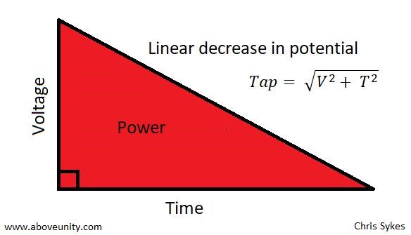
You have 10% ON and 90% OFF in input. I have seen this power triangle explanation, but don't you think that in 10% you have already paid for what is happening in the rest of 90%?


In all conventional Transformers, Energy is Transformed, Input is Transformed to Magnetic Force to Output Force, the M.M.F, or Ampere turn is equal and opposite less losses. Input M.M.F is Equal and Opposite to the Output M.M.F less Losses! Any time you offset the M.M.F, force, then you have more work in the System. 

This is the point of the Machine we build, to Offset the Input to Output M.M.F, to add M.M.F via the Third Coil!

Yes, it can be that these Waveform's can have Conventional Transformer Transformations, but we are not building a Conventional Transformer, that's the point of what we are doing.

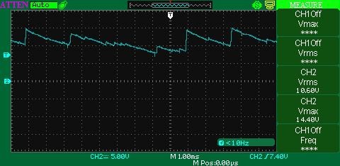
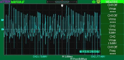
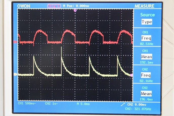
Someone tested some Melnichenko patent (some LCR circuit) and figured out that 1/4 (quarter) pulsing was beautiful - looks like you have 3 rising waves during ON and the rest 10+ are at decline. Measuring input and output (on resistor R) - revealed that there was nothing there.


A great deal of experiments performed by others are invalid, until one understands the Subject matter and thus the foll operation of a machine, experiments can be completely inconclusive! I have done many experiments that I look back on and think to my self, there is no way that could have worked, I did not understand the machine, if the slightest deviation in the Experiment you are performing from the original experiment, then the experiment is wrong. So we really can not compare unless we have everything 100% Correct and can verify that.

The waveform you show, is not like any Andrey Melnichenko Experiment Waveform I have ever seen and thus can not comment on its validity or verification.


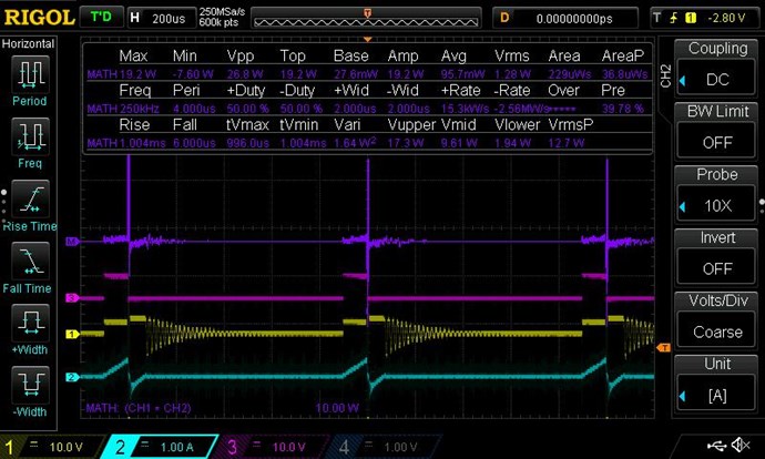
You have to measure input and output on resistive load, wave shape does not give you full info. Of course - wave shape shows you if you have ferro/wave/accousting/stochastic/whatever resonance.


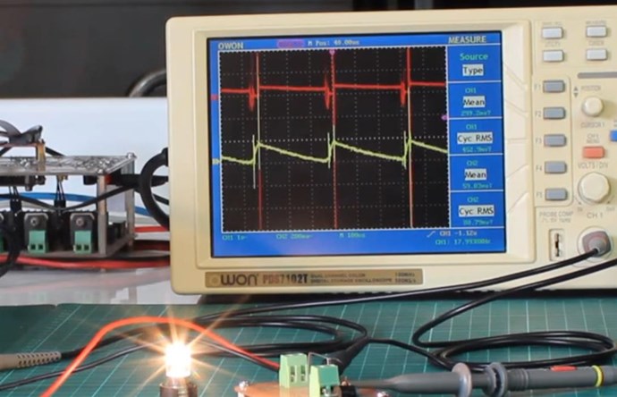
I always use Resistive Loads, an Incandescent lamp is largely a Resistive Load, this means Power is real, Voltage and Current are in phase - Yes.

It is correct to ask questions! No one should believe what might be ramblings of a crazy person! I expect all members to question everything, after all that's our job, in Research, is to question everything, until we understand it, totally and fully!

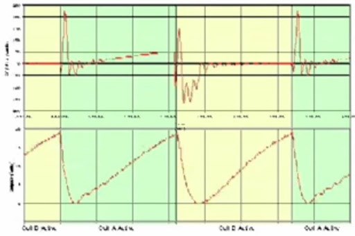
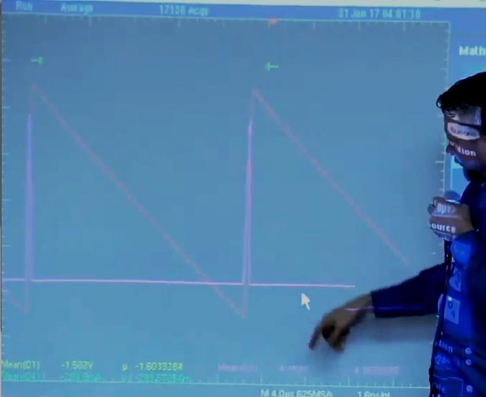
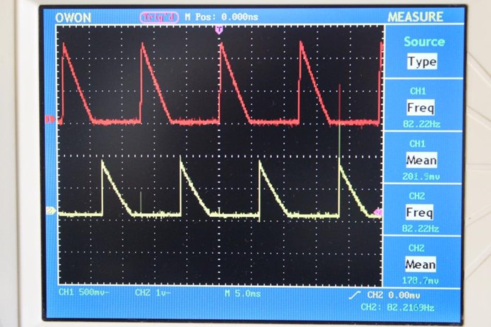
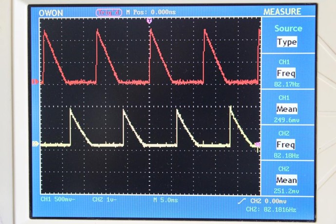
The Sawtooth waveform can be both Below Unity and Above Unity! Some examples I have given here on this forum, Don Smith, The MEG Team, Graham Gunderson, Tinman aka Bradley Richard Atherton:


There we go, okay you see the L1 coil here, it's three inch but Baker Williamson coil. Its had the four turns taken out of the center here and they're made into a pigtail which forms the ground the negative ground out or the amperage end of the deal. On the ends here or there coming off and going out and coming through, this is a series of very high-voltage capacitors, that are normally found in, flyback transformer circuits and televisions, so we're into the very high voltage on those diodes, and basically what they're doing, is what the two diodes were doing in the other device, they're taking a Sawtooth Pattern and changing it into a flat pulsating DC.


The Sawtooth Waveform is the Defining Lenz's Law Waveform!

I pointed out in my thread: Some Coils Buck and some Coils DONT why the Sawtooth Waveform is so important:

The Sawtooth Waveform is the Result of Lenz's Law, the very fact that Two Magnetic Fields are working together! This Magnetic Field Interaction is CRITICAL to understand! It is the EXACT Same effect as dropping the Neo Magnet down the Copper Tube:


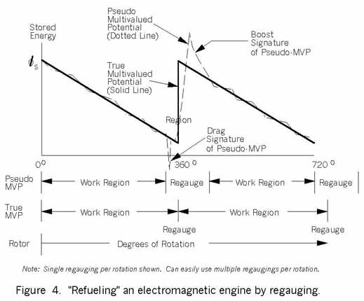
This is the reason the waveform has a Linear Decay, not an exponential decay! A Critical fact to observe and understand! 

The Sawtooth Waveform is the Defining Waveform for Energy "Generation"!

Ref: Me, Chris


A Conventional Transformer has all its Input M.M.F Oppose the Output M.M.F, and the Output = Input - Output - Losses, a Symmetrical Machine, Always Below Unity!

We are building a machine: Output = Input M.M.F + Tertiary M.M.F - Secondary M.M.F - Losses. An Asymmetrical Machine!

So, simply, we are using a Third Coil to add Energy to the System, via Electromagnetic Induction, that is over and above the Input to Output Ratio seen in a Conventional Transformer: Input : Output = 85%

Above Unity comes from the Total interactions of Magnetic Fields and Conductors outside the Conventional Transformer Theory!

This means, the more Electromagnetic Induction occurs outside of our Input period, the better off we are as a whole. Above unity comes from the Asymmetrical Interactions in our machine!


EXAMPLE:

We have $100 and we take it to the Bank. The bank charges us a fee to Bank the Money of 10%, so every time we bank money, we always end up with less money!

Today the Bank is really busy! We have to wait in line at the bank for 2 hours, we invoice the bank 20% of the $100 for our time in the queue. Now we have made 10%, so we have a gain, $110 in the bank for only the $100 we banked.


The Sawtooth Waveform is the direct Action, Reaction pair of Energy "Generation" is pointed out above, I have pointed this out in other places also. Realising others may not understand the significance, see the importance, I felt it needed its own Thread!

Best wishes,

   Chris

Order By: Standard | Newest | Votes
Chris posted this 09 March 2020

My Friends,

For most here, these process I am describing will make sense, we have covered for a long time, in detail. But for new comers, this subject in its own thread perhaps is a better way to see it from a fresh point of view.

I would like to point out another example:

If we have a Conventional Generator. There is equivalent Output Coil M.M.F to Shaft Torque. This means, Output = Shaft Torque - Losses! This is why Science says the Energy Input to a "Generator" is greater than the Energy Out of a "Generator"! Again we have covered this before, but again for clarity:


τ = r F sin θ


Where:

  • τ = Torque in units of Newton-meters.
  • r = Radius in units of meters (m).
  • F = Force in units of Newtons (N).
  • θ = Angle between F and the lever arm.


Now, we must realise: 1 Newton Meter ( N-m ) = 1.00 Joules ( J ), there we have our Torque to Electrical Energy ( Watts = Joules per second ) Output Equivalence, not counting Losses, in a "Generator", as pointed out by Floyd Sweet:

resistance, impedance, friction, magnetic hysteresis and Eddy currents and windage losses...

Ref: Nothing is Something - Floyd "Sparky" Sweet.


We can Invoke Electromagnetic Induction and have no Shaft! A Transformer is the Machine that achieves this task!

What we have in our System, is a method to Assist the Input! We can assist the Input, with a Clever means, and if we Halve our Input and make up the Half with an assisting Coil, so we have Energy "Generated" the same for the same Input, then the Energy we Input is less by Half!

This means, Energy Gains are possible by Clever, Smart means of Electromagnetic Induction! You will remember me pointing out:

One build-up has produced up to 100 times more power than was input.

Ref: cheniere.org


What is going on? The MEG has "Generated" 100 Times the Energy that was Input! Very simple, nothing difficult about this! All other Energy Machines do the same thing!

All Energy Machines use the same or very similar techniques! They must, the Energy we see on the Output must be "Generated"! We have shown you how to offset the Force, seen in the "Generator" as Torque, in the Transformer as Counter-E.M.F, as Joules Per second, to see a Gain!

The Gain, you must see a Gain over and above the Input Power, but this is only possible if you "Generate" the Energy with the Force Offset, something that can only be learned in time and improved upon over time. Charge is Separated ( Voltage ), then it is Pumped ( Current ) from the Copper Atoms in the Wire. Einstein's Mass Energy Equivalence! We have covered this also!

That's why I have done what I have, encouraging everyone to do the Experiments I have encouraged!

We are going to have to push past the Boundaries we let ourselves be bound by if the Human Race is ever going to climb out of the Mud! We have to be a lot smarter, and use our Brains as they were meant to be used!

This basic understanding is very important! It takes understanding and practice to build the perfect "Generator"! It takes understanding and practice to build the perfect Above Unity Machine!

Best wishes,

   Chris

Chris posted this 10 March 2020

My Friends,

Wow, amazing:


Note: 

the SW t7 wind turbine can handle wind speeds between 2 and 25 m/s and convert that energy into electricity at higher wind speeds the unit shuts off for safety reasons

Ref: 14 : 39 The Making of a Wind Turbine | Exceptional Engineering | Free Documentary


Also Note:

there are currently two ways to generate electricity out of wind, in the first option, the rotors rotation is passed on through a series of gears to a small generator, and the other the rotor directly powers a large generator

Ref: 26 : 20 The Making of a Wind Turbine | Exceptional Engineering | Free Documentary


You will note, Wind Energy is not Electrical in nature! There is no Electrical Connection from the Shaft to the Output Terminals! We have a Conundrum! How does the Coulombs of Charge get to the Terminals? How does the Coulombs of Charge become Pumped? All readers should know the answers here!


Nothing has changed in over 100 Years!


If they only knew about Partnered Output Coils! The Cost! WOW! The dismantling when it comes time to retire is phenomenal! I am at a loss to believe why so much money would be spent on such things, then the cabling into the Grid!

Best wishes,

   Chris


Chris posted this 10 March 2020

My Friends,

The significance of the Sawtooth Wave under some circumstances is a beneficial waveform to have! Why? Well we know for sure, the Action Reaction Pair from Input to Output Coil invokes this very waveform. I have shown this many times:


The Coils M.M.F to M.M.F ratio is 0, equal and opposite M.M.F is achieved:

PrimaryM.M.F + SecondaryM.M.F = 0.


We have covered this before, many times. What is M.M.F?


Magnetomotive Force

MMF can be thought of as the magnetic equivalent of electromotive force. You can calculate it as -

Equation TMM: Fm = I × N ampere turns

The units of MMF are often stated as ampere turns (A-t) because of this. In the example toroid core-

Equation TMC: Fm = 0.25 × 2 = 0.5 ampere turns

Don't confuse magnetomotive force with magnetic field strength (magnetizing force). As an analogy think of the plates of a capacitor with a certain electromotive force (EMF) between them. How high the electric field strength is will depend on the distance between the plates. Similarly, the magnetic field strength in a transformer core depends not just on the MMF but also on the distance that the flux must travel round it.

A magnetic field represents stored energy and

Equation TMF: Fm = 2 W / Φ

where W is the energy in joules. You can also relate MMF to the total flux going through part of a magnetic circuit whose reluctance you know.

Rowland's Law: Fm = Φ × Rm

There is a clear analogy here with an electric circuit and Ohm's Law, V = I × R. The analogy with electric potential (voltage) leads to the alternate name magnetic potential. There is, however, then a risk of confusion with magnetic vector potential - which has quite different units.

A specific MMF is required to sustain a given field strength along a known path length -

Equation TMP: Fm = H × le

Practical coil windings are made from copper wire which has a current carrying capacity limited mainly by its cross-section. There is therefore a limit to the MMF of a coil in continuous operation of about 3.5×10⁶ ampere-turns per square metre of aperture.

Ref: Magnetomotive Force


In the equation: : Fm = 2 W / Φ, you can see W = Joules, so M.M.F is directly related to Energy! You will note, another way to calculate the same equation is: Fm = I × N ampere turns. Now we have to draw the conclusion, M.M.F is directly related to Energy as is Ampere Turns ( NI )


Question:

Is there a way to invoke M.M.F into a system and not have to Pay for it? Can Energy be added to a System without having to Pay for this Energy?


Answer:

Yes!


Solution:

Every single Changing Magnetic Field, a Static Magnetic Field add's no Energy, the Magnetic Field must Change in Time, can add Energy to a System! This is basic Electromagnetic Induction principles. No Rocket Science here.


Floyd Sweet in his papers spoke of a Motional Magnetic Field:

The source of energy is unlimited, the virtual vacuum of space itself structured by a motional electromagnetic field is the powerhouse.

Ref: Floyd Sparky Sweet - Nothing is Something


And:


 THE MOTIONAL E-FIELD

Of all the known fields- electric, magnetic, gravitational and motional E-field the only ones incapable of being shielded are the induced motional E-field and the gravitational field. The nature of the motionally induced electric field is quite unique; in order understand it more fully we must start by parting with a few misleading paradigms. When magnetic flux is moved perpendicularly across a conductor an electromotive force (E.M.F) is electromagnetically induced "within" the conductor. "Within" is an artefact of the commonly used analogy comparing the flow of electric current within a wire to the flow of water within a pipe. 

Ref: Floyd Sparky Sweet - Nothing is Something


In a Conventional Transformer, the Primary Coil has its own Motional Electromagnetic Field! The Secondary also has its own Motional Electromagnetic Field! The Conventional Transformer is a Symmetrical Machine! It need not be Symmetrical, it can be Asymmetrical! Using the Secondaries Motional Electromagnetic Field to Induce an E.M.F in a Tertiary Coil and thus when Loaded, adding its own M.M.F to the System! Free! This M.M.F costs us nothing!

As long as the M.M.F is in the right direction, we get:

PrimaryM.M.F + SecondaryM.M.F + TertiaryM.M.F = TertiaryM.M.F


I have given you the Solution, all we need do now is improve on it. Some here on this Forum already have running machines, so with all the evidence, it is futile to refute!

We are Light Years ahead of the other Forums!

   Chris

Chris posted this 23 November 2020

All Readers

I want to Stress about The Sawtooth Waveform. In the Thread: Some Coils Buck and some Coils DONT, I gave the different Waveforms and how each Waveform was different depending on how we Wound, and Connected our Coils.


Polarity Matters!

Here are the difference in Waveforms:


The second Waveform is very much more Linear that the first Waveform. - This is really important and we want to see this Linear and not the Exponential Curve. The Exponential Curve is not right, we need to see the Linear Decay or as close to it as possible, like this:

Energy comes from the Copper Atoms, Einstein's Mass Energy Equivalence, Outer Orbital Electrons, stripped away and accelerated down the Wire, 6.24 x 1018 = 1 Coulomb = 1 Volt, and 6.24 x 10¹⁸ Electrons per-second, past Terminal T1, = One Ampere.


The Source of these Electrons:


The Atom!

So, like we have been told, very specifically, focus on the Electrons and how they can be Accelerated inside the Insulation of the Copper Conducting Wire.

How we do this is via Asymmetrical Regauging!


I hope this helps!

Best Wishes,

   Chris

Chris posted this 24 November 2020

My Friends,

I posted some videos a bit ago, see my youtube channel: youtube.com/channel/UC-B9gZZShrbxp9YTWgRPsKw

Please listen, every sentence is important:


Download the Videos, save them, back them up. We have IT My Friends, we only need to apply the particulars.

Best Wishes,

   Chris

Chris posted this 27 November 2020

My Friends,

I have had a conversation with Vidura about Polarity and how some, even though they are getting great results, may not still have the Partnered Output Coils in the Correct Polarity.

My Friends, I have asked Vidura to help and point out possible, any noticeable polarity problems. The more help we are able to give others, and also the more perspectives, the better. Vidura is very advanced and has a great deal of knowledge, please heed his advice.


Electromagnetic Induction

The Sawtooth Waveform is directly the Interactions of the Magnetic Fields, Opposing, or when Electromagnetic Induction between your Partnered Output Coils is occurring.

The exact same phenomena is occurring here:


Please everyone, please study this, please make sure you have these exact same effects in your Coils, this is what we think of as Lenz's Law, but is the Change of Current in Time. This is dI / dt.


Linear Slope

We have a Linear Motion, or Slope in the Change in Current over Time, because the Current is directly Opposing each other, as in the above Videos.

We must have a slope that's as linear as possible:

Ref: Chris's Non Inductive Coil Experiment


Ref: Asymmetrical Regauging


The Work Region in the above Image, is the very Pumping of Current from the Source! The Atom! This is where we "Generate" excess Energy. Energy being V x I / T, or by its very definition: One Ampere  over One Second is One Joule! Remembering we must have 1 Volt for One Ampere to Flow! 


Resonance

At Partnered Output Coil Resonance, we have:

  1. A Specific Frequency.


At Resonance, we are able to reach maximum amplitude on Our Partnered Output Coils for the least Input!

Floyd Sweet told us: Reactive at Resonance

Use your Input Coil, specifically the Current Slope, or Rise over Run, to match to your Partnered Output Coil Resonant Frequency:


The Input Current rise, seen above, must match the Rise of the Partnered Output Coil Resonance! This is where you will fine the optimum efficiency and the Input can in some cases go Negative, use no Input Power! In fact have more power come back out at you!

I have shown you how to find this frequency:


My Friends, you have all the answers, all you need to do is connect the dots. Many of you, here, already have. I post this for incoming Members to help them out.

Best Wishes,

   Chris

Vidura posted this 28 November 2020

Hello Friends!

As some members started recently experimenting with the partnered output coils, I would like to help with some guidelines to get the polarity of the windings and diodes correct:

Let us suppose that we will build an asymmetric POC transformer(or generator). For simplicity we will assume a strait ferromagnetic rod as core. In the first case we will wind all three coils in the same winding direction. As the dot convention tells, as a marker for the polarity , we will put a dot mark at the start of each winding:

Wi will now use one of this coils as Input coil, with the dot terminal connected to the positive rail and the other terminal to our switch. During the on time all three dot marked terminals will go positive, and during the Toff they will become negative. 

Now we have to be aware of an important detail, as we use sometimes a pair of CW-CCW  coils in our POC. In this case  the coil which is wound different , than the other two, will also have an inverted polarity, so we have to put the dot marker in that coil on the end of the winding, to get our polarity correct. Like shown in the next schematic:

If we use a closed magnetic loop as core, we can apply the very same rules, just imagine to bend the strait rod, and form a toroid. In order to get opposing magnetic fields from the POC, we can force the currents with diodes in the desired direction, like shown in the following schematic:

In terms of conventional Electronic Engineering0, we would say, that we have a shorted coil via the diode during Ton, and a flyback on the other coil with the load during Toff. But this is only  a static  point of view, as the effect we are looking for is dynamic , with the correct parameters both coils have to conduct during Toff simultaneously, and we will see the desired sawtooth waveform. Thus once we have found the correct circuit connection and polarity, we have to adjust the frequency and duty cycle to get the timing right. We have to be aware, that the voltage on the terminals of the coils are responding virtually immediately to the switching, while the currents (charges) have inertia and delays, according the inductance, core properties and other parameters.

Hopefully this helps some, any questions please feel free to ask, many here can help for sure.

Vidura

drago posted this 29 November 2020

Hello Friends,

Thank you all for your good work.
@Vidura your guide is Insane man.Thank you for your time and wish to help us all understand.
@Chris thank you for keeping the website up and for your efforts.

Now,guys I think people can not replicate what Chris  / Fighter's work...is because they do not understand how things work
( Including me )...but with your help it can all be changed.

I have some questions that would help greatly if better understood.

INPUT COIL :

1.Can the Basic switch , DC - COIL -Mosfet Drain - Ground ,be a replacement for an Audio Amplifier ?
I have seen this switching circuit in @Chris's posts and now in your post @Vidura.
I have played with this circuit for 3,4 years ( other experiments,not POC ) and when the MOSFET turns OFF , There is a LARGE transient - voltage spike ,that can blow the mosfet or damage the DC Power suply.
Between the coil and the Mosfet I always placed a DIODE to redirect the Voltage spike.
As In your schematics there is no diode on the TRIGGER , how will that end for the mosfet and DC power Suply guys ?

2. In the TRIGGER coil / Switch is it correct to state that the TOTAL amount of current drawn from the DC power supply it is Dictated by OHM's Law?

V divided by the total resistance of the circuit?


3. Because of the DOT being the positive rail,the current will follow the GREEN arrow....EXCEPT when we throw in a DIODE and Force the current to go Our Way.
That means,that the Current will be forced to flow OUR WAY until the diode is there,but when the diode gets damaged or something,the current will flow HIS way.Is this correct ?


As a final question, is there a big diffrence between rods and closed magnetic loops as toroids and AMCC cores ?
Until my AMCC core comes from CHINA I have only the Ferrite rods,and not matter what I do,I can not find any saw tooth in them.

Thank you very much guys.
Keep up the good work.
Much love and health to you all.
@drago


Vidura posted this 29 November 2020

Hey Drago For the first question: This circuit is a DC pulsed circuit, and can not be made with an audio amplifier, because it outputs AC. You should look for some information about the EMF of self-induction and the B(ack)EMF of inductors. Any inductor stores energy in form of a magnetic field when the current increase, and release it again when the current decreases. At the closure of the switch the current drop very fast, producing the BEMF transients. If this energy has no path to be drained, components can be damaged. Your can protect your switch with a MOV ( find info in the switching tool user's guide). Anyway in a transformer with several coils, the BEMF will appear on all coils simultaneously, this is why it should not be a problem in our case, it will be captured by the output coils. 2. Question No the current is not defined by ohms law, as for inductors it is calculated with the impedance Z , which is the sum of its inductive reactance and it's DC resistance. 3. In the schematic the coil you marked would conduct in the sense of the red arrows with and without diode during the on-time! of the switch, when it turns off the polarity of all coils reverse and the dot terminals become negative. Anyway as I have stated before, the current flow has inertia, tending to continue flowingin the same direction. A lot to study, go step by step. If you have a scope, place current sense resistors on the output coils, and observe the behaviour. Try to replicate the Mr Preva experiment(for this you can use the audio amplifier). The last Question, yes there is a difference between the metglass cores and Ferrite, frequency and saturation, but it works with Ferrite as well, as Captain Loz has shown. Vidura.

Chris posted this 10 December 2020

My Friends,

Recently, we have seen some chat here, on the Fly Back Converter. Some public and some private.

I want to state and emphasize two things:

  • It is beneficial to know how the Fly Back Converter works!
  • The Fly Back Converter does not produce Energy in Excess Amounts! This is NOT the cause of Above Unity Machines!


However, the Fly Back Converter is close, thus the reason I say it is worth studding! 

We see a Sawtooth Waveform in the Fly Back Converters:

Ref: Snubbing the flyback converter


NOTE: Marked as D2, this waveform is important, we have seen this before! It is our basic required Waveform!

Another good resource to read up on is: The Flyback Power-Supply Architecture and Operation is worth a study!

The key to Above Unity Machines are, Resonance and Asymmetry, the two aspects are not, in any way incorporated in the Fly Back Converter!

I want to stress: The Fly Back Converter is NOT the Cause of the Energy "Generation"!

The “flyback” name is due to the sudden stop/stop, on/off action of the MOSFET switch, with a waveform that looks like a sudden reversal of current flow.

Ref: The Flyback Power-Supply Architecture and Operation


The Fly Back Converter is normally restricted to Below Unity due to well known Rules. However, Amplifying Current by Pumping Electrons beyond the Boundary of Unity Minus Losses, requires the application of Fields capable of working beyond the Symmetrical Bounds, and into the Asymmetrical Realm.

In other words, a Greater M.M.F in the System, than we Input! This is Gravitational, the very Inertia of Mass, and not really "Fly back" as the cause!

I have said before: An Electric Generator is the Closest analogy to Our machines!

Best Wishes,

   Chris

We're Light Years Ahead!
Members Online:
What is a Scalar:

In physics, scalars are physical quantities that are unaffected by changes to a vector space basis. Scalars are often accompanied by units of measurement, as in "10 cm". Examples of scalar quantities are mass, distance, charge, volume, time, speed, and the magnitude of physical vectors in general.

You need to forget the Non-Sense that some spout with out knowing the actual Definition of the word Scalar! Some people talk absolute Bull Sh*t!

The pressure P in the formula P = pgh, pgh is a scalar that tells you the amount of this squashing force per unit area in a fluid.

A Scalar, having both direction and magnitude, can be anything! The Magnetic Field, a Charge moving, yet some Numb Nuts think it means Magic Science!

Message from God:

Hello my children. This is Yahweh, the one true Lord. You have found creation's secret. Now share it peacefully with the world.

Ref: Message from God written inside the Human Genome

God be in my head, and in my thinking.

God be in my eyes, and in my looking.

God be in my mouth, and in my speaking.

Oh, God be in my heart, and in my understanding.

Your Support:

More than anything else, your contributions to this forum are most important! We are trying to actively get all visitors involved, but we do only have a few main contributors, which are very much appreciated! If you would like to see more pages with more detailed experiments and answers, perhaps a contribution of another type maybe possible:

PayPal De-Platformed me!

They REFUSE to tell me why!

We now use Wise!

Donate
Use E-Mail: Chris at aboveunity.com

The content I am sharing is not only unique, but is changing the world as we know it! Please Support Us!

Thank You So Much!

Weeks High Earners:
The great Nikola Tesla:

Ere many generations pass, our machinery will be driven by a power obtainable at any point of the universe. This idea is not novel. Men have been led to it long ago by instinct or reason. It has been expressed in many ways, and in many places, in the history of old and new. We find it in the delightful myth of Antheus, who drives power from the earth; we find it among the subtle speculations of one of your splendid mathematicians, and in many hints and statements of thinkers of the present time. Throughout space there is energy. Is this energy static or kinetic? If static, our hopes are in vain; if kinetic - and this we know it is for certain - then it is a mere question of time when men will succeed in attaching their machinery to the very wheelwork of nature.

Experiments With Alternate Currents Of High Potential And High Frequency (February 1892).

Close