Some Coils Buck and some Coils DONT

  • Topic Is Sticky
  • Topic Is Locked
  • 7.8K Views
  • Last Post 17 February 2019
  • Topic Is Solved
Chris posted this 18 September 2017

In the document I published: Guidelines to Bucking Coils, I outline several configurations of Coils that work as Bucking Coils. There is a reason I did this, because other Configurations, do not work as Bucking Coils! At least not as well as the main configurations!

This is the reason for this Thread!

This is a partial continuation of the Thread: Steps to Avoid Failure

I said some time back, on ou.com, in a conversation with Bradley (Tinman):

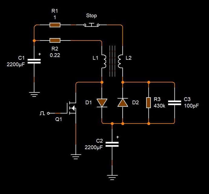
Importantly, each Coil is drawn, as a parallel Connection to each other, with a Diode, a Switch, and a mysterious "Shorting" Circuit drawn in a single square box. This is shown by Point A and Point B in the below schematic. There is a secret here that only those that have followed and read what I have said will know, so, all Single Pole Electric Motors may not work for this reason!

EMJunkie (Me, Chris) - Partnered Output Coils - Free Energy


Bradley replied with a bit long post: (Part Post Quote)

Im not sure what your reason is,but it is true that not all universal motors will work straight up. Some may require that the coils be rewound on the stator-->as in the case of my larger universal motor.

Tinman (Bradley Richard Atherton) - Partnered Output Coils - Free Energy

 In my years of learning, some Coils Buck and some Coils don't! This is due to the configuration of the Coils!

This is another reason why The Mr Preva Experiment is so important!

One way that does not work, is, take two pieces of wire and wind then Parallel, Bi-Filar, side by side, in the same direction.

In the same fashion, the Coils shown below, do not work: ( At least I have not had any luck with this configuration )


These Coils are identical, the same type of coils measured to be the same Inductance and also have the same turns.

These Coils are placed axially in the same direction with the turns in the same direction, on the Core. Seen in the above picture.


What Does Work

The Core has a Magnetic Field Polarity, an A Vector Potential Polarity, and the Direction of Velocity of the said Polarities. What does this look like?

An Image I have been showing for many years now! You can see, the letter "A" is the A Vector Potential, it has a Curl and a Polarity of the Curl. I have called this a Spin Direction. Also there is a North Pole Polarity and a South Pole Polarity. My Research has led me to believe there is a Bloch Wall, sometimes referred to as the Equator.

Using this information, we can now start to use this to improve Winding Direction and Placements.


Configuration One

Two Identical Coils, one flipped over from the other relative to the Axis of the Core:


Configuration Two

One Coil wound Clockwise, and one Coil wound Counter Clockwise relative to the Core:


Both of the above Configurations have pros and cons! Each are good but not one is specifically preferred, but can have advantages independently of the other.

   Chris


Order By: Standard | Newest | Votes
Chris posted this 19 September 2017

So, lets Experiment:

Take the following basic circuit, and test the Coils above:

 Some may see a similarity here to the Akula Circuit and also The Mr Preva Experiment Circuit.

 My below experiments are for guidance only and are not conclusive!

Note: 

  • Polarity One: is in Bucking Mode, the round Current peak on the Red Channel is an indication of the Bucking!
  • Polarity Two: Non Bucking Mode, the Magnetic Fields are not opposing. Impedance is seen by the Source (10V Input) and as a result we see a Voltage drop on the Input and a little more Current used.
  • We would normally see the Currents 180 Degrees out of Phase from Red Channel to Yellow Channel. The Diodes are forcing the Current to flow in one Direction.


Bucking does not Work - Experiment:

This experiment investigates two identical Coils, both in the same winding direction relative to the Core, utilising both Polarity's on one Coil only (Closest to the reader):


Polarity One:


Polarity Two:


Bucking does Work - Cfg One - Experiment

This experiment investigates two identical Coils, one Coil flipped over relative to the Core, utilising both Polarity's on one Coil only (Closest to the reader):

 
Polarity One:


Polarity Two:


Bucking does Work - Cfg Two - Experiment

This experiment investigates two identical Coils, one Coil wound Clockwise relative to the Core and the other Coil is wound Counter Clockwise relative to the Core, utilising both Polarity's on one Coil only (Closest to the reader):


Polarity One:


Polarity Two:


Results

A lot can be gained by examining the results!

   Chris

Chris posted this 05 October 2017

For those following, we see some very interesting results for the Current Wave Forms...

Remember, Current is the Magnetic Field, Changing in Time!

The base Frequency and the Duty Cycle was not changed during my experiments!

  • 82.29 Hz
  • 50% Duty Cycle.

So, in an Electronic Circuit, the Applied Voltage is something like this:

However, we see a big difference between the Time Constants in the Coil Configurations! A massive difference in point of fact!

A typical Time Constant looks something like this:

Where:

  • Blue Trace is the Applied Voltage across the Inductor.
  • Brown is the Current, Ramping up as the Voltage Applied (On), and Current Ramps down as Voltage is not Applied (Off). This is where we normally see a Voltage Spike: Flyback. We see this Ramp Down on the Yellow Wave Form.


From fastest to slowest:

Note: Red Trace is the Current Trace we are looking at. 

Bucking does not Work - Experiment:

This experiment investigates two identical Coils, both in the same winding direction relative to the Core, utilising both Polarity's on one Coil only (Closest to the reader):


Bucking does Work - Cfg One - Experiment

This experiment investigates two identical Coils, one Coil flipped over relative to the Core, utilising both Polarity's on one Coil only (Closest to the reader):


Bucking does Work - Cfg Two - Experiment

This experiment investigates two identical Coils, one Coil wound Clockwise relative to the Core and the other Coil is wound Counter Clockwise relative to the Core, utilising both Polarity's on one Coil only (Closest to the reader):


In this last scope Shot, Cfg Two, we can see that the Current is still High and the Switching is kicking back in again! You can see, the Generation of Electrical Energy, by Opposing Coil Configurations, is cut off by the Switching back in of the Applied Voltage, at a 50% Duty Cycle.


  • This is a super important fact to see! It is critical to understand the importance here!


  • This is all occurring with absolutely no cost on the Input, the Input is not affected, loaded, in anyway at all here!!! 


So, a way to keep the Electromagnetic Induction going longer, is to reduce the Duty Cycle. Down, shorter in time, so there is more Off Time, and the Coils can Interact together, over a longer time.

Don't forget, Voltage is the Number of Turns (N) in the Proximity of a Changing Magnetic Field. E.M.F = -NdPhi/dt

   Chris

Wistiti posted this 19 February 2018

Some coil buck and some don’t.... but when dealing with pulsing dc as input, this is what you can see... For sure we can find more! Hope you enjoy! Ps: thank you again Chris my freind for what you share!!

Attached Files

Chris posted this 01 February 2018


   It is time...

In the above Experiment, we can very clearly see the Time Rate of Change of the Magnetic Fields:

Remember, Current is analogous to the Magnetic Field, they are the same things, Current is also analogous to M.M.F, or Magnetomotive Force.

The below image, bottom trace in particular, is showing a Linear Time Constant, this is not consistent with the images shown above, where a Ramping Down of the Current was shown, but Why?


This is perfectly normal, this is Lenz's law, the same exact effect seen in the Magnet Falling through a Copper Tube Experiment. Lenz's Law, Equal and Opposite, a Linear Change in Time. 


This is seen as Drag in the Mechanical "Generator" and the reason, more Shaft Torque is required, on the Shaft, as the Load Increases on the "Generator". Which is why we see an Increase on the Input.

The below image is showing a totally different situation! The bottom Yellow Trace shows the typical Ramp Down curve shown above in the Time Constant Images, it is a Non-Linear curve - But Why? 


What I am showing you, is:

Energy "Generation" without loading the Source Magnetic Field

The Magnetic Field is Free to move in the System, the Magnetic Field is Not Loaded, there is Zero Lenz Law Drag on the Source Magnetic Field! Everyone should be able to see this, and I am very surprised no one has commented about this!

By counter balancing the Force in the System, we have the ability to reduce our Input to only the Cost of producing the Magnetic Field in the First place.

As I have pointed out, the magnetic Fields are:

1 + -1 + 1 = 1

An Asymmetrical System! We are not consuming our Input, like a Symmetrical System: 1 + -1 = 0

This is so Important! A concept that will change the world forever!

   Chris

Chris posted this 30 September 2018

My Friends,

We have seen a common theme across the board.

This thread gives perhaps the best experimental evidence of Coil Interactions we have studied. I have released some Circuits to help, to start a Modular Thinking of the technology.

NOTE: If one were to line up all the Circuits of Output Coil Combinations in all Energy Machines over the years, one would see a precise pattern, as an example lets take only two:


Don Smith:


Akula ( Roman Karnaukhov )


Now, except for an extra Capacitor, the two Circuits are identical! The polarity and thus the Diode on L2 are reversed, but other than that they are Identical.

WHY?

As we have learnt, we require the Coil Interactions to "Generate" excessive Energy. Our Input is the primer for, or the Catalyst for, the Pump. The Pump is the Interactions between the Coils.

Antenna Theory is all about the efficient transfer of Energy, radio waves, so the receiving device can receive the most efficient and strongest signals. It was said by Floyd Sweet:

Resonance frequencies may be maintained quite constant at high power levels so long as the load remains constant. We are all familiar with AM and FM propagation, where in the case as AM, the voltage amplitude varies, and with FM, the frequency is modulated.

However, the output power sees a constant load impedance, that of the matched antenna system. If this changes, the input to the antenna is mismatched, and standing waves are generated resulting in a loss of power. The frequency is a forced response and remains constant. Power is lost and efficiency becomes less and less, depending on the degree of mismatch.

Ref: Floyd Sparky Sweet - Magnetic Resonance.


NOTE: Akula ( Roman Karnaukhov ) is a Radio Engineer.

Ironically, we have a huge volume of data, showing that a Tuning of sorts is required to make the machine operate correctly. We have the reason why, we must tune, to reduce Input Power, and increase Output Power!

Using Frequency and Duty Cycle, we can tune into a Machines Magnetic Resonance. Akula has many videos showing the process of adjusting for the correct Frequency and Duty Cycle:


Aiming for "Harmonic Resonance using Frequency and Duty Cycle", as in Antenna Theory is the key. We are nearly there my friends!

   Chris

Chris posted this 19 September 2017

The conclusions gained from the above Experiments are quite astounding when realised!

Electromagnetic Induction occurring with absolutely no extra impedance on the Input! Twice in the one System!

No parameters were changed other than the Coils during this set of experiments. But, we see quite different results!

In this particular Circuit, Configuration Two in bucking mode appears to be the most beneficial! CW/CCW Coils.

  • 0.680 volts RMS
  • 192.1 ma mean
  • 196.4 ma mean

Compared to where Bucking does not Work, not very well anyway:

  • 0.587 volts RMS
  • 55.18 ma mean
  • -19.97 ma mean

and the next best configuration after Configuration Two, Configuration One:

  • 0.624 volts RMS
  • 150.9 ma mean
  • 172.2 ma mean

We see a Voltage Drop, same as we get in The Mr Preva Experiment! This Voltage Drop indicates several things, and needs some attention!

It is worth noting, many Circuit improvements could be made, E.G: Positive Feed Back. I have not made any optimisations at all here.

   Chris

Chris posted this 05 October 2017

The Cycle of Action:

1: The Input is switched on, Voltage is applied across an Inductor, the Current Ramps up according to the RL Time Constant:


2: The Input is switched Off. At this point we have a Magnetic Field inside the Core. The only Cost to us is I2R Losses.


3: The Magnetic Field starts collapsing, a Magnetic Field Changing in Time is one requirement for Electromagnetic Induction, Inductive kick back, and the Current Ramps Down according to the RL Time Constant: Shown as the Decay Phase.


4: Because we are smart and wish to build Asymmetrical Systems, we have another Coil, a second output Coil, and this Coil is also subject to the same Electromagnetic Laws that the First Coil is. As a result, we get a different Waveform, indicating an almost half sinusoidal waveform, showing that Electromagnetic Induction can occur more than once in a single System! Asymmetric Electromagnetic Induction!

So, in this experiment, we see a Timing Cycle some what resembling the following:


Where:

  • First, Top Red Trace indicates the Switch On, the Voltage applied across the Inductor.
  • Second Red Trace is the Current from Electromagnetic Induction in the Second Coil.
  • Third Yellow Trace is the Ramp down of Current in the first Coil due to Electromagnetic Induction.

   Chris

devesh posted this 08 November 2017

After having received your invitation to join the aboveunity.com community and finished reading all of the above posts of yours (just this thread), dear Chris, I can state that I am a lucky man surrounded by exceptional people: I sincerely hope to be of any help with my own experimentation.

Devesh (Fabrizio)

Chris posted this 19 February 2018

@Wistiti - This is a beautiful example! Thank you for sharing!

@All - Please pay special attention to what Wistiti is sharing, this is so important to see and understand!


Current (I) is subject to several things:

  • Ohms Law: I = V / R
  • Magnetic Field: Core size is limited to so much Magnetic Field
  • Wire Diameter: 0.33mm wire could be replaced by 1.0mm

By increasing the Output Voltage, this, in combination should increase the total Output.

Beautiful work and thank you for sharing my friend!

   Chris

Chris posted this 17 February 2019

My Friends,

This thread has gone missed. Very few views. No real replications, one person.

I want to show something. Above, my best result:


Now, we have lots of things going on here. We see at the start of the wave, one wave falling ( Yellow Trace ), we see the other wave rising ( Red Trace ).

There is a point where the traces meet:


Seen above, is a point where the traces meet, one current down Hill, one Current Up Hill. This occurs at 88Hz, 50% Duty Cycle.

I want you to ask yourself: What has caused the Current ( Red Trace ) to rise like this? Why do we see a point where they meet?

Yeah 50 vs 100 mv but you get the idea.

   Chris


Chris posted this 03 October 2017

I am really surprised more interest has not been shown here! 12 views in 2 weeks.

This is perhaps one of the most important articles I have ever written, with work shown and with lots of pictures to show important points.

This work and the Circuit is almost exactly the same as the Andrey Melnichenko's GLED and Akula Works! Also as Ruslan's "Flashlight without batteries" (Фонарик без батареек) shown below! I am very surprised more interest has not been shown!


Any ideas on how to make this more interesting?

   Chris

Chris posted this 04 October 2017

I guess the point is, just putting a few coils on a Bobbin and trying to make it work, is very clearly not a good way to go about these experiments!

A detailed set of experiments to see why some coils work and some don't will be necessary!

For example, my above experiments confirm what we already know! Akula shows this exact same ideal Coil Configuration: CW/CCW


Electrical Energy is "Generated" and a 187 year old Law tells us how this is done! Faradays Law of Electromagnetic Induction!

Transformers are not Above Unity simply because there is a One to One Energy Transformation, a Symmetrical System, but we know, for sure, the System must be Asymmetrical! Many hundreds o Devices through out history have shown us this!

A small Pulse invokes a Large Induction, I show Non-Conventional Inductive results in my Experiment above! 

   Chris

Chris posted this 06 October 2017

I hope those following can see the importance of experiment, documentation, and special attention not to over look the smallest things.

The reason I say this, is simply because I did for so long!

The smallest finest details can lead to the biggest descoverys, although some of this is already known in Electronics Engineering, it is still a very important feather to have under ones Hat!

We have seen much of these sorts of things before:

 
Fig One - Graham Gunderson - The reason for the Non Uniform Sinusoidal Wave, I explain above.


Fig Two - Akula Time Constant - The Time Phase of Energy Generation.

I hope this helps others and not confuses. I have made an extra special effort to explain the best I can with detail. But, ask, if you have questions, and I will try to help further.

Done forget, we here at http://www,aboveunity.com or are Light Years ahead of all the other forums! So there is no need to be shy, a lot of catch up will be required if you have come from another forum.

Besides, no one here gets picked on! We are all here to help each other! Our No Trolls Aloud Policy is the Only Rule here.

  Chris

Chris posted this 21 February 2018

For all watching, this Thread is based on an experiment I did way back in: April 17, 2014, at the time I already had a fair bit of experience with Partnered Output Coils publishing my first video: 18 Jul 2011 - Self Assisted Oscillation in a Shorted Coil - Bucking Magnetic Field Oscillation.

The experiment I shared partly, was shared to: Akula0083 30 Watt Self Running Generator


 As you can see. other than the diodes being shown/not shown, its almost exactly the same experiment.

What Wistiti has shown is very important, important Effects! I have always said look for the effects.

Akula, when showing his early device, also saw these effects


Very simple, the Interactions between the Coils are what "Generates" excess electrical Energy! Magnetic Fields changing in Time, Turns of the Coils, and the Circuitry, controlling the 'ON' and 'OFF' times.

But, again, don't take from your Input, your Input must not be affected by reflecting Magnetic Fields or you will only ever end up with a Transformer, and perhaps not all that good of one.

Its true, Ruslan Kulabuhov has also told you the same thing:

Now for removal:

1. The coil is connected via a diode bridge. No parallel capacitors !!!

2. You need from Tesla only one half wave. Otherwise Tesla will take what she gave, back !!!

Therefore, and put the diode from the ground to the very take-off coil (40m) The shark did this at the reception. He removed one part of the sine at the reception itself. Because Tesla. No one knows this and -bip-tsya to this day, nichrome does not work. It's clear! You need to swing the swing in the coil of energy removal. It is there that we push the current. By the way, the surplus from Tesla and the frequency setting of the Shark used a simple light bulb. Since the Inductor is galvanically isolated from the entire circuit, the light bulb serves as a resistive load to suppress surplus from cords and pickups.

   Chris 

Chris posted this 10 October 2018

My Friends,

What is critically important, is Engineers will tell you: "the Winding direction makes no difference".

This Thread does not only prove that winding direction does make a difference, but it is also beneficial in one Direction. Such a simple experiment, yet I have seen not a single iota of evidence else where for or against it.

As an experiment, find yourself an Electrical Engineer, ask the same question.  Nine of ten times you will get the answer I have just provided, if not ten of ten times.

The Human Race still has many very simple things to learn!

   Chris

Chris posted this 03 October 2018

My Friends,

Floyd Sparky Sweet wrote about his study of Paul Raymond Jensen's UDT Transformer.

I quote:

Referring to the Jensen machine stated: natural magnetic resonance freq = 2.80GHz the nuclear magnetic resonance of a free electron when charges in magnetic states are induced by magnetic field the changes in states causes a condition called electron paramagnetic resonance, or EPR. The EPR of a free electron is 2.80 H MC. Where H is in gauss. This should be the initial state of the defining mathematical format.

and:

Resonance frequencies may be maintained quite constant at high power levels so long as the load remains constant. We are all familiar with AM and FM propagation, where in the case as AM, the voltage amplitude varies, and with FM, the frequency is modulated.

However, the output power sees a constant load impedance, that of the matched antenna system. If this changes, the input to the antenna is mismatched, and standing waves are generated resulting in a loss of power. The frequency is a forced response and remains constant. Power is lost and efficiency becomes less and less, depending on the degree of mismatch. Let’s assume the Jensen amplifying transformer is in a resonating condition. Its output is connected to a transmission line which is X number of miles long. Without any customer load at all, power will be required to change the line. This will present capacitive reactance, XC = 1/2 fc.

and:

The power factor cos ϴ angle will be leading, though negligible on short systems. The effect must be reckoned with on multiple grid long systems operating above 60 KV. What we have is a capacitor and the effects are evident as line impedance. Another parameter is varying power factor due to changing inductive loads. Taken together this forms a complex impedance load continually varying and this is what the “Jensen” machine will “see” when connected to power distributing network grids. Such a resonant machine will never sustain resonance as shown in the sketch. The circuit consists of a capacitor in series with an inductor and this is a series resonant circuit of minimum impedance and maximum current. Theoretically, the current limiting is effected by series resistance in the circuit including the resistance of the inductor,

Many can likely detect an element of skepticism in Floyd Sweets writing. A natural response for an ignorant mind, the mind that does not understand Energy and how it is "Generated"! Once a mind understands Energy, how Energy is actually Separated, we technically term this as "Generation", then one can use logic to make sense of what others cant, as Floyd Sweet did!

The Input Coils Paul Raymond Jensen spoke of are very simple to understand:

The UDT is composed of a parallel LC resonant primary


What is the configuration of the Output Coils, notice the plural use, Coils not Coil. Paul Raymond Jensen understood exactly what he was doing:

The two secondary windings are wound on the two outer legs of the core and are series connected.


Paul Raymond Jensen used a "Feed Back Winding", as did Floyd Sweet:

Now consider the "feedback winding." It is connected in series with the secondary and is wound over the primary winding on the centre leg of the core.


Reading and carefully applying statements to conceptual design, we see a machine taking shape:


Of course, if the Ampere Turns of L3 >= Primary Coil, then the Primary is loss less, and the phase angle will be at, or beyond, 90 Degrees..

We were told, specifically:

The magnetic flux from the two secondary windings cancels in the "outer leg circuits," leaving only one-quarter of the total flux generated by the output current to react back upon the primary. This resulted in a current gain in the secondary, relative to the primary. Lenz's law was bypassed, and free-energy resulted. An alternate explanation for the current gain in the UDT is to consider each secondary winding as acting as the primary winding for the other secondary winding when an output current is drawn because the two secondary windings generate geometrically opposing fields.


Is this starting to look vaguely familiar? It should, we have seen this many times in many devices:


Its everywhere, like I have been saying for years now, the Interactions of Two Output Coils, Partnered Output Coils are where Excess Electromagnetic Induction occurs!

   Chris

Jagau posted this 30 September 2018

Hi Chris excellent post,

this is what i am searching for!

and this is what ( i thing) have noted on my last experiment.

And this is a low harmonic what you are talking about


Quote from ruslan:

Created by Tesla. In the coil another wave is formed under the action of pumping by rectangles. The particles of which constantly rotate left and right.


Jagau

Wistiti posted this 05 October 2017

really interesting my friend!!!!!

  • Liked by
  • Chris
  • Augenblick
Chris posted this 28 September 2018

My Friends,

I have unlocked this thread. Please stay on Topic.

Recent discussions from some Members warrant this topic open.

   Chris

  • Liked by
  • Vidura
  • Augenblick
Chris posted this 01 October 2018

Hey Jagau,

I had a feeling this might have been useful in light of your recent successes!

I have more data coming soon, but I urge all following, I may not always be right, I am still learning, I am sharing my observations. That's all.

We are currently at a stage, new comers will have trouble catching up, this is the reason I have laid a trail as I have. I hope our work does not disappear into oblivion as have most others throughout history!

   Chris

  • Liked by
  • Augenblick
  • ISLab

Topic Is Locked

We're Light Years Ahead!
Members Online:

No one online at the moment


What is a Scalar:

In physics, scalars are physical quantities that are unaffected by changes to a vector space basis. Scalars are often accompanied by units of measurement, as in "10 cm". Examples of scalar quantities are mass, distance, charge, volume, time, speed, and the magnitude of physical vectors in general.

You need to forget the Non-Sense that some spout with out knowing the actual Definition of the word Scalar! Some people talk absolute Bull Sh*t!

The pressure P in the formula P = pgh, pgh is a scalar that tells you the amount of this squashing force per unit area in a fluid.

A Scalar, having both direction and magnitude, can be anything! The Magnetic Field, a Charge moving, yet some Numb Nuts think it means Magic Science!

Message from God:

Hello my children. This is Yahweh, the one true Lord. You have found creation's secret. Now share it peacefully with the world.

Ref: Message from God written inside the Human Genome

God be in my head, and in my thinking.

God be in my eyes, and in my looking.

God be in my mouth, and in my speaking.

Oh, God be in my heart, and in my understanding.

Your Support:

More than anything else, your contributions to this forum are most important! We are trying to actively get all visitors involved, but we do only have a few main contributors, which are very much appreciated! If you would like to see more pages with more detailed experiments and answers, perhaps a contribution of another type maybe possible:

PayPal De-Platformed me!

They REFUSE to tell me why!

We now use Wise!

Donate
Use E-Mail: Chris at aboveunity.com

The content I am sharing is not only unique, but is changing the world as we know it! Please Support Us!

Thank You So Much!

Weeks High Earners:
The great Nikola Tesla:

Ere many generations pass, our machinery will be driven by a power obtainable at any point of the universe. This idea is not novel. Men have been led to it long ago by instinct or reason. It has been expressed in many ways, and in many places, in the history of old and new. We find it in the delightful myth of Antheus, who drives power from the earth; we find it among the subtle speculations of one of your splendid mathematicians, and in many hints and statements of thinkers of the present time. Throughout space there is energy. Is this energy static or kinetic? If static, our hopes are in vain; if kinetic - and this we know it is for certain - then it is a mere question of time when men will succeed in attaching their machinery to the very wheelwork of nature.

Experiments With Alternate Currents Of High Potential And High Frequency (February 1892).

Close