Reduced Impedance Effect

  • Topic Is Sticky
  • 3.4K Views
  • Last Post 29 March 2020
Chris posted this 12 August 2017

This experiment is from my PDF document: Guidelines to Bucking Coils. P.14

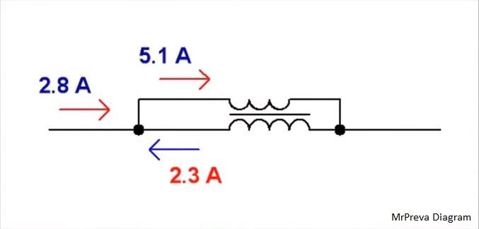
Partnered Output Coils have a unique but well known effect to those in the know, of Reduced Impedance Effect.

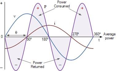
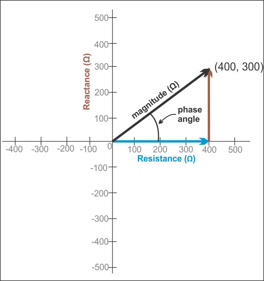
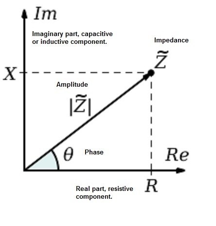
A Coil of Insulated Conductive Wire has two components to its Resistance, both combined into the Coils Impedance (Z).

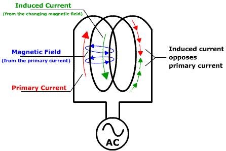
Impedance (Z) is made up from Inductive Reactance (XL) and Capacitive Reactance (XC). Reactance is the Resistance to change of the Magnetic Field. For example, the Coil will exhibit a Force, a Magnetic Field in opposition to its own changing Magnetic Field, if you like a Lenz's Law effect inside the Coil, to its own changing Magnetic Field.

 
Ref: eeweb.com - Inductive Reactance


The Coil's Impedance may be represented with Real and Imaginary Numbers.

An example may look like this:  Impedance (Z): 0.957826285221151+j3.193 in Ohms Ω

Where:

  • 0.957826285221151 is the DC Resistance in Ohms
  • 3.193 is the Inductive Reactance also in Ohms
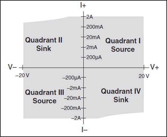
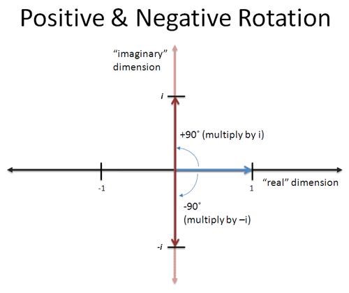
  • +j is the Imaginary Number, indicating that Inductive Reactance is dominant, -j indicating Capacitive Reactance is dominant.

This example is from a series of equations examining a Coil at 10 Volts, 3 Amps and 50Hz.


The Experiment

Two Circuits, with two sets of results are to be examined. In this examination, we are looking specifically at the Current in the Coil. In both scenarios, the Lengths of the Coils will not change, only the configuration of the Coils. The Coil has two strands, bi-filar by its very definition.

Each Wire is 55.6mH individually, 55.6mH parallel and 0.231H Series connected. DC Coil Resistance is 3.8 Ohms each Wire and 1.9 Ohms parallel and 7.8 Ohms Series.


Circuit One:

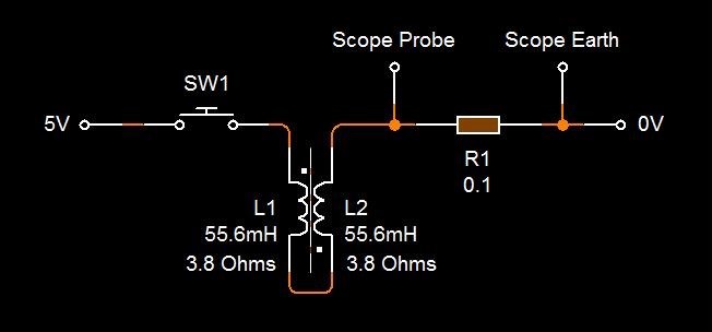
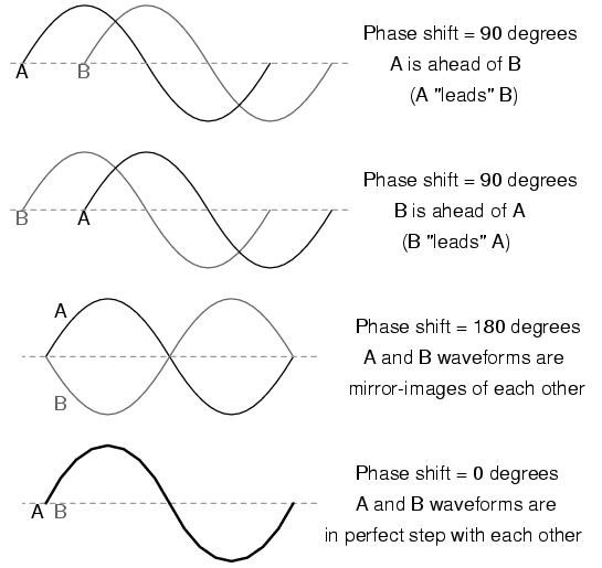
Where:L1 and L2's Magnetic Field are in the Same Direction on the Core.


Circuit Two:

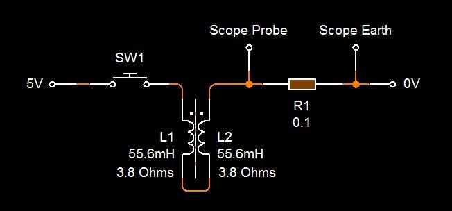
Where:L1 and L2's Magnetic Field are in the Opposite Direction on the Core.
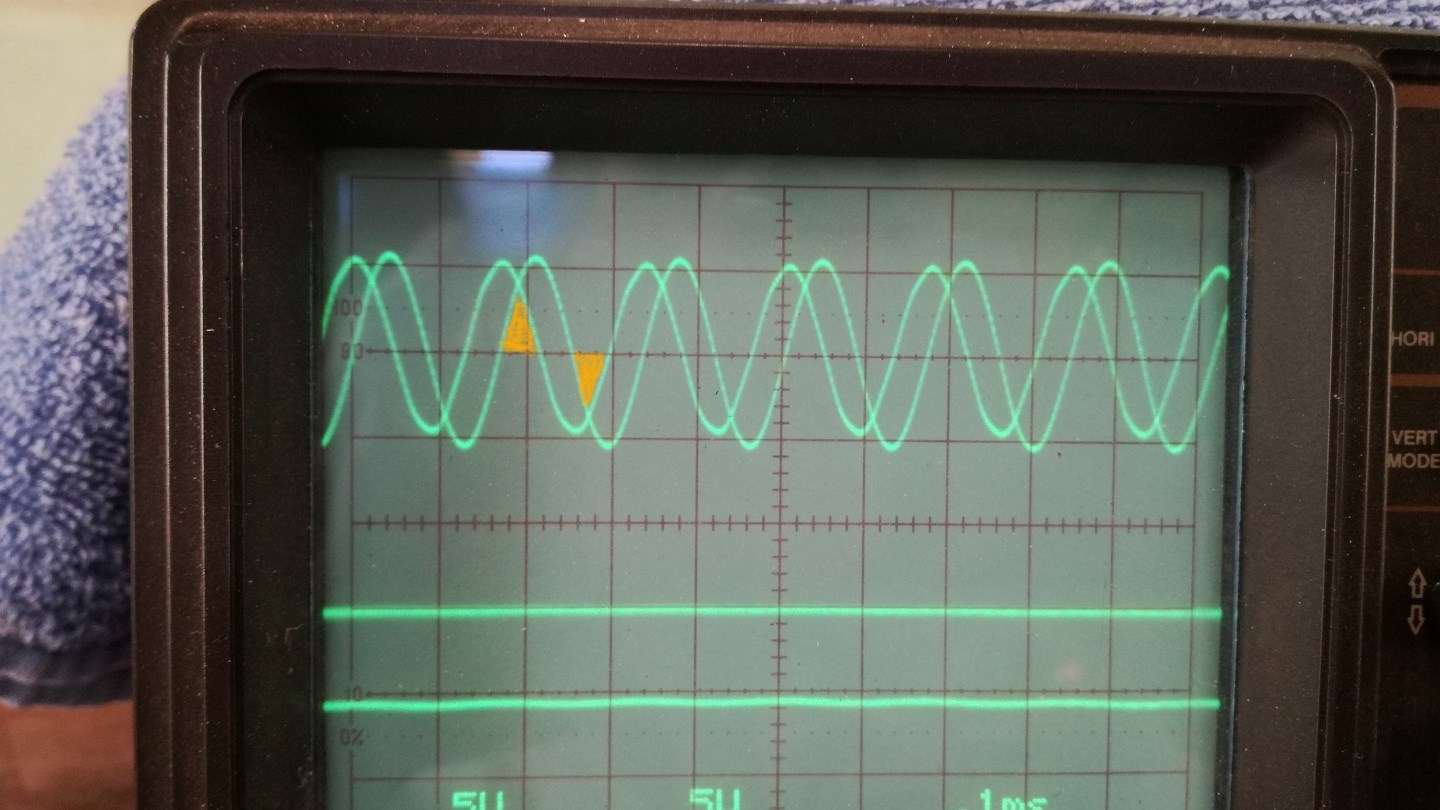
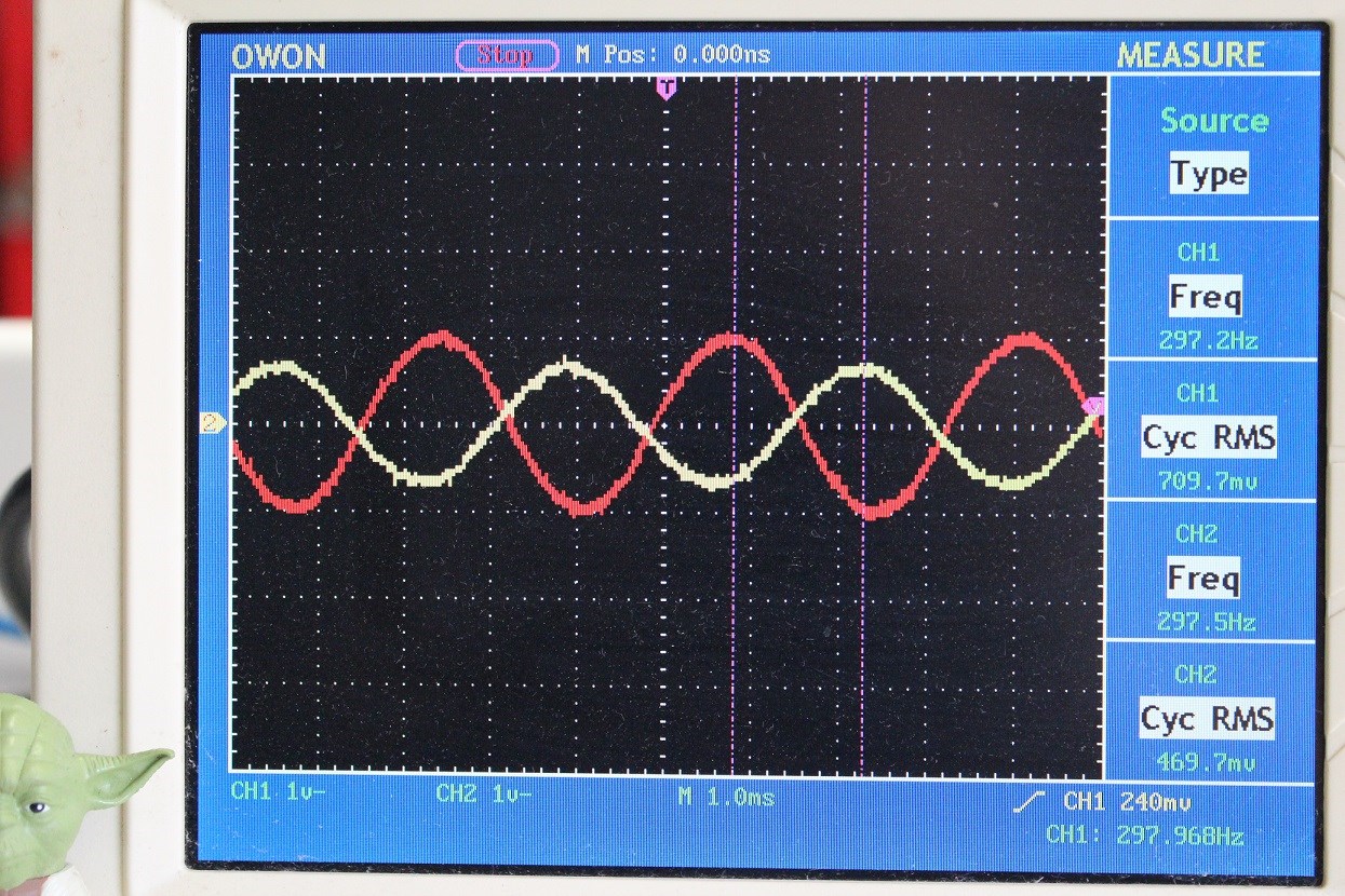
 

Results:

This is an expected behaviour for the Current in the Coil when the Inductance Changes.

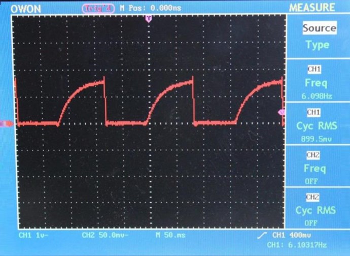
For the Magnetic Field in the same direction:


For the Magnetic Field in the opposite direction:


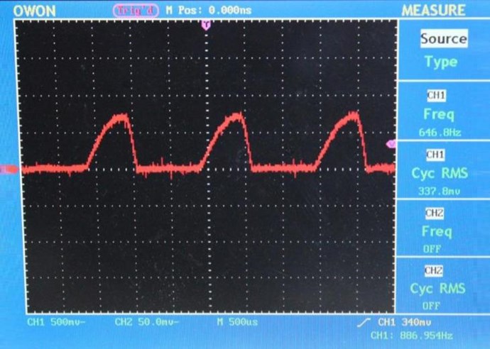
Here we have shown that for the same Resistance, (7.8 Ohms Series), that the Current Flow in the Conductor can move at a MUCH Faster rate even though the Resistance of the Conductor has NOT Changed! This proves that the Magnetic Field Slows the Charge Flow Rates dramatically. The Speed of the Flow Rate, 650 Micro Seconds (๐œ‡๐‘ ) compared to 75 milliseconds (๐‘š๐‘ ) for charge time with the Magnetic Field.

The Impedance is now Reduced, Reduced Impedance Effect, we have lost the components of Inductive Reactance almost entirely. Thus the Impedance (Z) is nearly at zero, only leaving the DC Resistance.

I hope this experiment is valuable to you, as it was for me in understanding how this change in Magnetic Fields can greatly influence the way a Coil behaves!

   Chris

Order By: Standard | Newest | Votes
Chris posted this 29 March 2020

My Friends,

Today is historical! If you were present, you would have seen something that no one has ever seen before, my jaw falling to the ground in astonishment!

In helping a friend of mine, I looked up a link, it was to do with this thread:


Google has Indexed and Cataloged The Reduced Impedance Effect in a specific Snippet, WOW I never thought I would see the day!

The world as we know it has changed! The Google Censorship Algorithm has changed as has been reported and is now indexing things that it would otherwise not have!

Today is a great day! The world is changing for the better! This is proof!

Best wishes,

   Chris

alohalaoha posted this 12 December 2018

KNOW HOW Impedance Matching for experimenters


Attached Files

  • Liked by
  • Chris
  • Vidura
Chris posted this 13 September 2018

My Friends,

I ask, a word we must take seriously: Clue

When ever we see evidence, there is always, guaranteed, a way to Experimentally Verify and give rise to Hard Fact!

I want to share a quote from an old Document, attached below in a Text File:


Observation of machine output voltage of approximately 120 VRMS while the load was changed in 100 watt increments from 100 watts to 1000 watts has shown no observable output voltage change, which suggests an extremely low internal equivalent impedance.

The 20 gauge magnet wire in the output coils consisting of several hundred turns has significant DC resistance which is not correlated with the unvarying output terminal voltage at different loads.

It is speculated that this energy does not travel within the copper wire or its passage through the copper wire does not generate a voltage drop - a most useful feature when transferring energy from one place to another.


In other words, the Reduced Impedance Effect! The Experiments I have shared with you!

Look for those Facts that can be proven, put all else in the maybe later bucket, let only Logic and Common-sense lead your path of research!

Study this statement:

The VTA can be started by momentary connection of a 9 volt battery to the drive coils when the machine is operated in the self-powered mode.

The operation is stopped by momentary interruption of power to the power coils.


Very careful study of the above statement reveals a very simple definitive answer - There is no confusion! 

   Chris

Attached Files

Chris posted this 12 September 2018

My Friends,

Another quote, one to match the above quote about Negative Power Factor:

How does the Space Flux Coupled Alternator appear to operate beyond unity? An approximate analogy, not by any means perfect, is as follows:

Picture a side-wheel paddle steam boat making its way down stream in the same direction as a fairly strong tidal flow.

Assume the steam engine to be highly efficient, say 80%. Now assume the engine to be working at this efficiency and that the tidal energy integrates with that of the engine in propelling the ship. The acceleration increases to a point where the horsepower increases beyond that equivalent energy consumed by the engine. If one were not aware of the tidal flow energy integrated with that of the consumed energy, one would conclude the engine efficiency was greater than unity. This is hypothetical. As the momentum of the tide relates only to the mass of the steamboat’s displacement of the medium, water. Actually if the forward momentum of the tide was able to relate only to the paddle wheel the forward or positive force would tend to force the wheel to turn in the opposite or negative direction.

Then in the hypothetical case, the force of the tide on the mass of the ship would equal the force acting on the paddle wheel and the ship would be motionless. In order to move in the forward direction, the engine would need to overcome the negative force of the tide on the wheel. Little engine HP would be needed, as it would integrate with the positive flow of the tide, acting on the displacement mass of the ship. The above is not achievable in practice, as the only way the tide could relate to the paddle wheel in such a manner, the mass of the ship would have to be completely out of the water and only the wheel within the flow of the tide would turn, as the momentum of the flow of the tide would not be in effect.

This is reactive power – no work is done.

The wheel turns but the ship is motionless. Conversely, if this were a possibility, then a ship moving against a strong tide, would be able to traverse a river without either engine of sail, by means of the force of a moving mass of water against the wheel paddles. As stated, the force of the mass of water flowing against the displacement mass of the ship predominantly opposes the positive motion of the ship. The analogy though far from perfect, suggests that if one were not aware of the visible force acting on the movement of the ship, at times, assuming all parameters were measurable, the indication might be that the engine was capable of greater than unity efficiency.

In the case of the Space Flux Coupled machine, there is no visible entity. It’s abstract. A steady state coherent force is present when brought under the influence of the electromagnetic controllable forces. It returns to an incoherent state when the initiating magnetic forces are absent (except in the case of a permanent magnet).

Ref: Floyd Sweet - The Space-Flux Coupled Alternator


If you have been following, a Eureka moment will no doubt have struck you! The close approximation to the above analogy is perhaps more than uncanny!

Study, understand, make those important connections, the importance is crucial!

   Chris

Chris posted this 10 September 2018

Hey Vidura,

Happy to help. and glad I finally understood your query!


@All readers,,

It is really important to note:

cos(180) = -1.0


No amount of math manipulation will ever get rid of the Negative Signs in Electrical Engineering and nor should the Negative Signs be made to disappear! Only Bad Science and Bad Engineering will result in the manipulation and elimination of Half of Real World Science!

Don't be fooled by an ingrained doctrine, insisted upon by poorly trained and thoughtless minds only reciting what they have read, and applied to memory, not realising this is not Science!

Your Mind, one of the three most powerful things Given!

   Chris


P.S: there is not another forum on the planet that has covered this topic in such detail with Experiment and supporting Scientific evidence to support these concepts! This is Hard Data that has been avoided and missed deliberately by those that do not wish you to have it! We truly are Light Years beyond the others!

  • Liked by
  • ISLab
  • Plasmonic
Vidura posted this 10 September 2018

Well explained! Yes  now I understand, thanks for your patience Chris!

  • Liked by
  • Chris
  • ISLab
Chris posted this 10 September 2018

Hi Vidura,

Ah, yes, I was also taught, Area under the waveform! However, we must take into account the Direction of the Power:


Waveform's V, blue, and I, red, are shown, with Power waveform being shaded in Purple.  You can see the meaning of the term: Ping Pong Power here. Power delivered is also returned. Remembering all systems have losses.

Technically, this diagram should be marked as:

  • Power Delivered.
  • Power Returned.


A video explaining some details, but also with the error I mentioned, made a point of, above!


A better video:


FOUND it, this guy is awesome!


I hope this explains your question?

   Chris

  • Liked by
  • Vidura
  • ISLab
Vidura posted this 10 September 2018

Thank's for your post Chris,

there is something that have to be revised in this theories. My doubt was specifically about the case of pure reactive power, VAR's.

If we consider the case of a phase shift of 90° or 270° , which in the four quadrant model is considered as VAR's  PF=0    I have noted in the transformer tests that at this phase angels there is an overlapping area where voltage and current are simultaneously present:

Considering this it becomes obvious that there is a power transfer in this condition. the only condition where there is no overlapping(always considering a sine wave) is at a phase angle of 180°, When the voltage is of opposite sign relative to the current. 

The example of the railway locomotive makes clear that there has to be a neutral point , when the motor is between load and generator condition , the point when no power is transferred in any direction, and that this point is when the powerfactor is  0.

Now looking back to the four quadrant model, if at powerfactor 0 , pure VAR's  as it is obvious no power is transferred; it does not make any sense to assign a positive  or negative sign to VAR's and declare delivered or recived Var's ??

If I have missed something, or an erroneous concept, i'll apreciate if anyone can explain me.


  • Liked by
  • Chris
  • ISLab
Chris posted this 09 September 2018

Hi Vidura,

I do apologise for missing your question. I am not sure I fully understand your meaning, so if I stray away from your meaning, please let me know!

Power is considered Active, or Real Power when Voltage and Current phase angles are 0 or at 180 degrees.


At 90 degrees or 270 degrees, this is called Wattless Power, or Reactive Power ( Q ), Power that Ping Pongs back and forth from the Source and Sink. This is VAr, Volt Ampere Reactive. Power that is considered to do no Work.

This is because at any one time Current is not present when Voltage is and vice versa. We have one, but not the other.

This fact begs questions, and deserves real answers, however I am unable to give a proper response. The fact that Voltage and Current can be detected and measured goes against current theory, Theory states we must apply a voltage before a Current can flow, however with out an applied Voltage a Current can still flow...

Of course Resonance creates situations where things do change!

PF, Power Factor, ranges from -1 to 1. This fact is not taught in most Textbooks! Wikipedia does explain this. Most textbooks state specifically that Power Factor ranges from 0 to 1,which is wrong by very definition!

A definition for perusal:

What is a negative power factor? What are the reasons for this? Is there any harmful effect on a small capacity gas engine for a negative power factor?


Sonal Garg, studied Bachelor of Technology in Electrical and Electronics Engineering at Dr. A.P.J. Abdul Kalam Technica...


In alternating current (AC) power systems, power is defined as the rate of energy transfer. At most measurement locations on a grid, the energy transfers in a single direction, typically from a source (such as a power grid) to a load (such as a house). But at certain locations, the energy transfers in opposite directions at different times, for example from/to a grid to/from a housed equipped with photovoltaic solar panels.

In these situations, it is common to measure negative power, that is, power flowing from the nominal load towards the nominal source.

Given that Power Factor is universally defined as the ratio between power and volt-amps, and given that volt-amps is always positive(Volt-amps is the product of r.m.s. volts and r.m.s. amps. The square term in r.m.s. ensures that r.m.s. values are always positive) , we must conclude that when power is negative then Power Factor is also negative.

A negative power factor occurs when the device (which is normally the load) generates power, which then flows back towards the source, which is normally considered the generator.

For example, if an induction motor is used to operate an electric railway locomotive, the power factor will be lagging by less than 90 degrees as the locomotive climbs a hill. If the motor is nearly loaded, the power factor might be about 0.85. If the track is level at the top of the hill, the motor's load will be reduced and the power factor might drop to 0.65. As the locomotive begin to go downhill, the power factor drops more and may be come negative as the motor begins to operate as a generator returning braking power to the source.

However, the fact that PF is negative means that active power is negative too. When you are considering a load, this means that the load outputs energy to the system, so it works as a generator. If you would consider a generator, the negative active power means it works as a load, so it takes energy from the system. This can happen in fact in one and only state, when the generator's turbine failed and rotation of the rotor is created by rotating magnetic field of the system (the generator works as a motor and it is rotating the turbine).

Hope this is helpful !


If we take One Volt, One Amp but have 0, 270, 180, and 90 degrees of phase shift between Current and Voltage waveforms, for Clockwise Revolution, under different Circuit Conditions at different times, we get the respective Power Factors: 

  • 0        =       1.0
  • 270    =       0.0
  • 180    =       -1.0
  • 90      =       0.0


Power Factor Definition gives us a clue:

under periodic conditions, ratio of the absolute value of the active power P to the apparent power S


In completing a full 360 degrees, or one revolution, we see a pattern. Reactive Power where the Imaginary numbers sit, they are all in the plane where a 0 Power Factor lay. A power Factor of 0.0 means we use no Power, 1 or -1 means this ratio is at maximum.

E.G:

  • 1 x 1 cos(0) = 1.0
  • 1 x 1 cos(270) = 0.0
  • 1 x 1 cos(180) = -1.0
  • 1 x 1 cos(90) =  0.0


Real Power, Active Power, we need to have 1 or -1. Where 1 is Real Power Delivered, -1 is Real Power Received.

   Chris


P.S: I apologise, I know you know most all this stuff already, I have included for completeness for others reading.

Vidura posted this 09 September 2018

Hi Chris, This information about the four quadrant model makes the relationship clear, but there is one question that I have already asked in my transformer threads: If we have in a situation pure reactive power with PF =0 , VAR , the net result of volts x amps over a cicle is zero. So why there is a sign in the axis of reactive power ? Is or isn't an energy transfer preset ? This question regarding delivered or recived VAR's.

  • Liked by
  • Chris
Chris posted this 09 September 2018

My Friends,

For your reference, The diagrams we are looking at, the Quadrants are often reffered to as: Source and Sink


Its worth noting, Floyd Sweet also referred to Source and Sink:


Just a handy reference to keep. This, while the "experts" debate power on the other forums.

   Chris


P.S: We truly are Light Years ahead of the others! wink


  • Liked by
  • cd_sharp
  • ISLab
Chris posted this 09 September 2018

Perhaps a little more, an example?

in the following diagram:


We see a statement that is very important to see the applied concept!

We see:

  • Voltage: Positive
  • Current: Negative
  • Power: Consumed


If we take the Example of The Mr Preva Experiment, we see Voltage is Positive, Current on one Coil is Negative. I shared the following scope image:


With the following Data:


Input:
Period: 3.320
Offset: 0.160
Degrees: 17.3
Active: 2.203788426168
Apparent: 2.30821
Reactive: 0.686403717929
Power Factor: 0.9547608


L1:
Period: 3.320
Offset: 0.28
Degrees: 30.4
Active: 8.0004243646859
Apparent: 9.275707
Reactive: 4.6938212608966
Power Factor: 0.8625137


L2:
Period: 3.320
Offset: 1.72
Degrees: 186.5
Active: -6.1948770793364
Apparent: 6.234956
Reactive: -0.7058169710592
Power Factor: -0.9935719


Analysing each Coil individually, we get an idea on the required parameters to plot the data to the Four-quadrant representation of active/reactive power in motor and generator mode. A rough throw together, not plotted with any accuracy, can be seen here:


Red and Green dots showing the Coils approximate positions. You can see, the Red Mark is in the Power Received Quadrants, slightly below, 186 Degrees is a slightly more Capacitive rather than Inductive Power Received. The Green Point, is forward Power, 30 degrees, having some Reactance.

Lets move this all up a notch! Lets show the world we mean business!

A little light reading attached below.

   Chris

Attached Files

Chris posted this 08 September 2018

My Friends,

For quite a few years I have shared data on what I call The Reduced Impedance Effect. How this effect works is rather complex for those new comers to Electrical Engineering. I have shared this data before here.


The Argand Diagram:

The Argand diagram Definition:

a diagram on which complex numbers are represented geometrically using Cartesian axes, the horizontal coordinate representing the real part of the number and the vertical coordinate the complex part.


What appears to be missing from this definition, is the fact that the Argand diagram is commonly used in Rotational physics. 

We have a situation in EE where Impedance is a combination of Real Numbers and also Complex Numbers but also rotation, or one could say direction if one wanted to bend some rules a little to understand this a little better.

This is what an Argand diagram looks like for Impedance:


More commonly seen as:


An Argand diagram looks like for Rotation:


Power Analysis uses the same chart:


IMPORTANT:

In this mode, it is considered: "Generator Mode Inductive" you can see this marked on the above diagram! This Quadrant is what we see in The Mr Preva Experiment! Voltage and Current are 180 Degrees out of phase! A Negative Power Factor, because we are "Generating" Energy, this Coil has become a "Generator"/Battery!


This gives us the Negative Effective Power Factor we have covered in our Pages.

My research has led me to believe that the term "Negative Resistance" is incorrect by definition! I have come to believe from results that DC Resistance remains in all Elements. The Element itself can become a Battery, but still contains its own internal Resistance!

The reason for this post, is, the progress we see others making, we need to make sure we do not follow the same mistakes! We "Generate" Energy by the Separation of Charges. There is no Magic, no Voo-Doo, no complication to basic easy to explain principles. 

   Chris

alohalaoha posted this 13 August 2017

Ingener99's experiment from 2015. RIE effect verification

Reduced Impedance Effect - Currents are in the Opposite Direction. On the left is rf-choke. Source of power - pure sinus inverter 20a, 250 hz.

Chris Sykes Experiment.


Iingener99 channel

https://www.youtube.com/channel/UClwroKTD-1ipAjs9cHHXpTQ


We're Light Years Ahead!
Members Online:

No one online at the moment


What is a Scalar:

In physics, scalars are physical quantities that are unaffected by changes to a vector space basis. Scalars are often accompanied by units of measurement, as in "10 cm". Examples of scalar quantities are mass, distance, charge, volume, time, speed, and the magnitude of physical vectors in general.

You need to forget the Non-Sense that some spout with out knowing the actual Definition of the word Scalar! Some people talk absolute Bull Sh*t!

The pressure P in the formula P = pgh, pgh is a scalar that tells you the amount of this squashing force per unit area in a fluid.

A Scalar, having both direction and magnitude, can be anything! The Magnetic Field, a Charge moving, yet some Numb Nuts think it means Magic Science!

Message from God:

Hello my children. This is Yahweh, the one true Lord. You have found creation's secret. Now share it peacefully with the world.

Ref: Message from God written inside the Human Genome

God be in my head, and in my thinking.

God be in my eyes, and in my looking.

God be in my mouth, and in my speaking.

Oh, God be in my heart, and in my understanding.

Your Support:

More than anything else, your contributions to this forum are most important! We are trying to actively get all visitors involved, but we do only have a few main contributors, which are very much appreciated! If you would like to see more pages with more detailed experiments and answers, perhaps a contribution of another type maybe possible:

PayPal De-Platformed me!

They REFUSE to tell me why!

We now use Wise!

Donate
Use E-Mail: Chris at aboveunity.com

The content I am sharing is not only unique, but is changing the world as we know it! Please Support Us!

Thank You So Much!

Weeks High Earners:
The great Nikola Tesla:

Ere many generations pass, our machinery will be driven by a power obtainable at any point of the universe. This idea is not novel. Men have been led to it long ago by instinct or reason. It has been expressed in many ways, and in many places, in the history of old and new. We find it in the delightful myth of Antheus, who drives power from the earth; we find it among the subtle speculations of one of your splendid mathematicians, and in many hints and statements of thinkers of the present time. Throughout space there is energy. Is this energy static or kinetic? If static, our hopes are in vain; if kinetic - and this we know it is for certain - then it is a mere question of time when men will succeed in attaching their machinery to the very wheelwork of nature.

Experiments With Alternate Currents Of High Potential And High Frequency (February 1892).

Close