Reactive at Resonance - The Geometry of Asymmetry!

  • Topic Is Sticky
  • 2.2K Views
  • Last Post 17 July 2020
Chris posted this 17 July 2020

My Friends,

I said some time back a new Geometry would come, remember Floyd Sweet gave us two geometries to think about!

I have struggled with "bi-filar" as the definition and the use has been very different historically!


Well, the first geometry I have given and we have covered very well so far! You know this configuration very well, now I think we need to cover the second geometry!

Bi-Filar Coils Definition is:

A bifilar coil is an electromagnetic coil that contains two closely spaced, parallel windings. In engineering, the word bifilar describes wire which is made of two filaments or strands. It is commonly used to denote special types of winding wire for transformers.


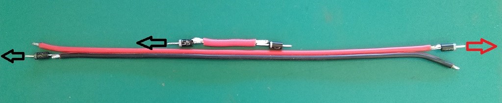
I have shown many images before about this, here is one:

Ref: Parallel Wire or Bifilar Coil Experiment


I want to stress, there is a lot to learn here, we need to pay very special attention, this information will link and make sense of other information that may not have made sense before. In saying this, please understand, this ends up with the same end result as the other geometry! Its just another method to get to the same end result, perhaps some small benefits here to make this more beneficial?

I have said all along: The two output Coils must be thought about as two separate coils, this is still the case!

This is the basic configuration I am employing:


This is the Machine I am using, you may recognize the Coils from my early experiments:


This is a Scope Shot:

Where:

  • Yellow = Input Current.
  • Teal = Input Voltage.
  • Blue = Output Voltage.
  • Purple = Output Voltage.


Note: Output Voltages are 180 Degrees Out of Phase! Yes I am measuring the opposite ends and this is to be expected. However, if we get the opportunity, where one Output Coil can "Generate" a Voltage on the other Output Coil via the Time Rate of Change of the Current in the other Output Coil, then this would be of benefit! The Bi-filar Coils are Unity Coupled and the Changing Magnetic Field in one, can "Generate" a Voltage in the Other!

Important: This configuration is set to 100Hz, I have not tuned this machine! Remember what Floyd Sweet Told Us! Reactive at Resonance! 


I need to point out, any coil with a Diode on the end that has an AC Signal should only ever output Half Wave AC:


I have placed my Probes on the other side of the Diode, to show the Full Wave, but on the other side of the Diode, we would normally get Half Wave Rectification! This needs to be realised. The Waveform I am getting is:


With some Frequency adjustment, I can get a strange, almost sinusoidal waveform:


Now you can see, this is not the Waveform we should be seeing!

In the Thread: The Field Structure of Nature, I pointed out a common theme in Nature, I believe this experiment proves that Electromagnetic Fields exhibit the same basic form:

:


The Curl of the Magnetic A Vector Potential, Cancels, but as it does so, the Fields do move past the Boundaries of the normal Magnetic Field we would normally observe! We have more than one Source of Energy. Each M.M.F, the Current ( I ) through Turns ( N ), and the Source is Equal and Opposite minus Losses, that's why we have a drop in Amplitude from one channel to the other. We have three M.M.F's to consider, each M.M.F the Current in each Coil and we have three Coils!

Remember what Sir Richard Feynman told us:


Each M.M.F, is a Source of Energy!

Every point, where we see Voltage on the Output Coils, "Generated", when we should be seeing this:

In particular the Half AC Waveform shown with the corresponding + in the Half wave, is what we should see, but we don't! This is because we have Voltage being "Generated" in three different Coils! An Asymmetrical System!


Please note: This experiment is for education purposes! A lot can be learned from this and similar experiments! I would recommend, for results, either Fighters ZPM, or my original experiment: Chris's Non-Inductive Coil Experiment may be easier to grasp and get results.

Please Remember: Two different methods to get to the same end result: Opposing Partnered Output Coils!

Also Note: Floyd Sweet's idea was to Integrate the Magnets Field into the Coils Fields for extra energy! I have shown no Magnets!

Also a lot can be done to improve this experiment! I have shown a few simple effects only! Just because my figures are not showing Above Unity here does not in anyway mean this experiment is not beneficial!

Best wishes, stay safe and well My Friends,

   Chris

Order By: Standard | Newest | Votes
Chris posted this 17 July 2020

My Friends,

Grounding the Output Coils, as is expected in Electrical Engineering Best Practices, does show what we would expect to see, Half Wave AC Rectification:


I should have been more clear and I made a mistake not to show you the Grounded Coils on the Output. Seems I had a bad day yesterday and made a few mistakes. Sorry Guys!

Please Note: This is not a Floating Ground, this is Fixed Earth Ground.

This means, any potential on this wire, has now been Earth grounded and is now the ground reference point on the Oscilloscope! This means we can not see any Potential "Generated" on this Terminal, because the "Generated" Potential has been Grounded. This poses a dilemma and is something that in History has come up several times, about Grounding Machines.

Of course, what is deemed as Parasitic Inductance, is not something that can just be Grounded and remove the "Generated" Voltage just like we have here, in the above scope shot!


We must observe the fact, a Change in Current, "Generates" a Voltage! This is di/dt, and this cant always be Grounded to make it go away!

Here is an example:


One Output Coil is Grounded and the other is floating. Where we would normally see a flat straight line, we see a small Curved line and the potential is not Zero as it is on the Grounded Output Coil!

The Current flowing in the Coil attached to the Pink Trace, "Generates" the Voltage peak, the small curve, on the Coil attached to the Blue Trace. Very simple, Electromagnetic Induction! Engineers call this Parasitic Inductance, but we want to use this, its an effect of Great Benefit when used correctly! It must be said, Engineers have been brainwashed into throwing away half of Science! embarassed

The first scope shot on this post is what Science expects with Half Wave Rectified AC as I pointed out in the first post.

I have shown that we throw away a lot of Engineering by not observing the bit that Science tells us to Ground! This is the part we need to take advantage of to make AU Machines!

Best wishes, stay safe and well My Friends,

   Chris

Chris posted this 17 July 2020

Hey CD,

I use a Sony Xplode Audio Amp, its under the bench, the power supply powers that. Its not very efficient.


Sometimes, learning something is as important or more important than results. This experiment is limited to the Coils capability, and the Output Coil has way too much Impedance to be useful! We have learnt in the past that the Output Impedance does limit how well these machines work!

You are exactly right My Friend:

It's just the knowledge of the coils and how they interact with each other

Ref: Steven Mark


A good, very timely quote My Friend!

Please Note; Re-reading my post yesterday, I noticed some inaccuracies, I have modified the post some in an attempt to be more clear about the experiment.

Best wishes, stay safe and well My Friends,

   Chris

We're Light Years Ahead!
Members Online:

No one online at the moment


What is a Scalar:

In physics, scalars are physical quantities that are unaffected by changes to a vector space basis. Scalars are often accompanied by units of measurement, as in "10 cm". Examples of scalar quantities are mass, distance, charge, volume, time, speed, and the magnitude of physical vectors in general.

You need to forget the Non-Sense that some spout with out knowing the actual Definition of the word Scalar! Some people talk absolute Bull Sh*t!

The pressure P in the formula P = pgh, pgh is a scalar that tells you the amount of this squashing force per unit area in a fluid.

A Scalar, having both direction and magnitude, can be anything! The Magnetic Field, a Charge moving, yet some Numb Nuts think it means Magic Science!

Message from God:

Hello my children. This is Yahweh, the one true Lord. You have found creation's secret. Now share it peacefully with the world.

Ref: Message from God written inside the Human Genome

God be in my head, and in my thinking.

God be in my eyes, and in my looking.

God be in my mouth, and in my speaking.

Oh, God be in my heart, and in my understanding.

Your Support:

More than anything else, your contributions to this forum are most important! We are trying to actively get all visitors involved, but we do only have a few main contributors, which are very much appreciated! If you would like to see more pages with more detailed experiments and answers, perhaps a contribution of another type maybe possible:

PayPal De-Platformed me!

They REFUSE to tell me why!

We now use Wise!

Donate
Use E-Mail: Chris at aboveunity.com

The content I am sharing is not only unique, but is changing the world as we know it! Please Support Us!

Thank You So Much!

Weeks High Earners:
The great Nikola Tesla:

Ere many generations pass, our machinery will be driven by a power obtainable at any point of the universe. This idea is not novel. Men have been led to it long ago by instinct or reason. It has been expressed in many ways, and in many places, in the history of old and new. We find it in the delightful myth of Antheus, who drives power from the earth; we find it among the subtle speculations of one of your splendid mathematicians, and in many hints and statements of thinkers of the present time. Throughout space there is energy. Is this energy static or kinetic? If static, our hopes are in vain; if kinetic - and this we know it is for certain - then it is a mere question of time when men will succeed in attaching their machinery to the very wheelwork of nature.

Experiments With Alternate Currents Of High Potential And High Frequency (February 1892).

Close