POC Experiments

  • 1.3K Views
  • Last Post 10 February 2020
OriginalSkywatcher posted this 25 December 2019

Hi all, I'm back to experimenting with the bucking coil technology, it seems to be the most promising and is within my resources.

Using a core made from stacked ferrite toroids, glued together.

Getting nice output and input current lowers when partnered coils are loaded.

As can be seen, have it set up to easily be able to try different wiring configurations, even a full coil length over the bucking coils option.

The multistrand coil to the right in picture is for a different project.

The 555 timer circuit is to the right in picture and the 6 watt led bulbs in back are used as a load.

Primary coil is 24awg. magnet wire, bucking coils are using 30awg. magnet wire.

peace love light


Attached Files

Order By: Standard | Newest | Votes
Wistiti posted this 25 December 2019

Hi Sky!

Good idea to use a 555 timer! Will love to seethe result.

OriginalSkywatcher posted this 31 December 2019

Hi wistiti, good to hear from you.

Yes, using the 555 timer with adjustable duty cycle works well.

What I noticed with my setup at the moment, (and of course it using one primary coil over half the core or over only one partnered coil), is that when pulsing the primary with the partnered coils in parallel as outlined by chris, with no load attached to the parallel output.

It seems the input increases a little, perhaps the coils are not perfectly matched and one is feeding into the other and causing a load to be seen by the input.

I will try and match those coils soon though.

However, I tried various partnered coil wiring methods and came upon one that did not change the input current when connected without load and with load, the input current decreases.

Also, my partnered coils are wound as chris suggests is best, counter clockwise and clockwise.

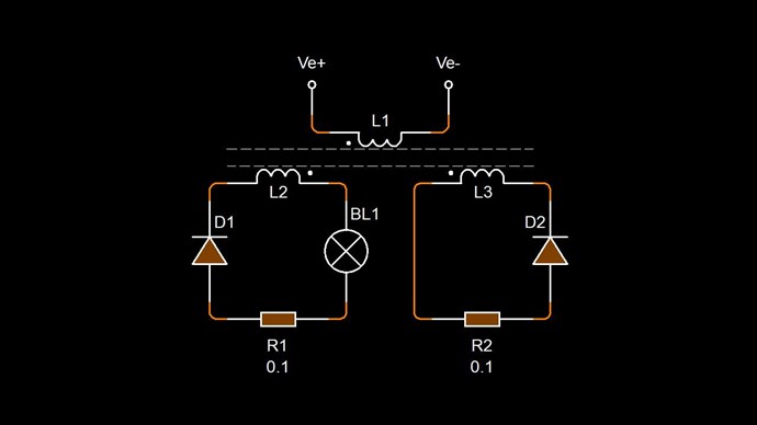
The wiring method used is placing the partnered coils in series, meaning, taking power from the wire end at each end of the core and connecting the partnered coils at the middle of the core, where the coils buck each other.

A standard, 6 watt, 120vac led bulb is used as load at the partnered coils output.

Then, a diode is placed across the second partnered coil, (with proper orientation to light the bulb brightly and cause a decrease in input current) the partnered coil that is NOT under the primary coil, so the coil that is furthest from the primary pulsing coil.

Without the 1N5408 diode across the outer partnered coil, in whatever orientation is needed, the led bulb brightness is cut in half and the input current increases a little.

Though with that diode in place, the led bulb brightness doubles and the input current decreases a little more below no-load input current.

peace love lightsmile


Chris posted this 31 December 2019

Hey Skywatcher,

Nice work, Thank You for sharing your results! Its good to know other experimenters are getting the same set of results that we are! 

I am glad you have joined our team!

   Chris

Wistiti posted this 01 January 2020

Hi Sky. Nice to read your experiment.

Im curious, have you also try connecting the POC output parallel? I mean the load between the center and the extremities of the POC?

Thank you for sharing!

OriginalSkywatcher posted this 04 January 2020

Hi chris, thanks for the kind words.

They seem like similar results, the coil/core is making a sawtooth like audible sound, so it is probably close.

Glad to be here chris.

Hi wistiti, yes, though that is when I noticed without load, the paralleled coils were increasing the input amps a little, compared to the coils disconnected from each other, with the 555 timer pulsing the primary coil with mosfet switch.

Though that may be due to the coils not being matched, not sure.

peace love ight

Wistiti posted this 04 January 2020

Hi Sky! Does your poc have the same number of turns?

I have try try with what Yoelmicro have share and it seem to be more efficient... Hope it will help!

"Wistiti posted this 24 October 2019

Thank you for the clarification, it is really appreciated!

So if i understand correctly N2 must be first a multiple of 7 and N1 is the same as N2 plus the number of time we have 7 turns in N2.

For example.

N2= 7 turns, N1 must be 7 +1 or 8 turns.

N2 = 14 turns (or 2 times 7), N1 must be 14 + 2 or 16 turns.

N2 = 70 turns (or 10 times 7), N1 must be 70 + 10 or 80 turns.

And so on...

Much more clear for me now! 

Thanks again for your contribution!

Permalink  7  1

Liked by     and 3 others

QuoteReport

YoElMiCrO posted this 24 October 2019

Hello everyone.

@Wistiti.

It turns out that in the transformers it is very difficult to make turns decimals, this is because once it enters the core It is considered a complete turn. There are methods to make half turns, using the posts sides of the E-transformers, but this is not the case. That is why the best relationship of turns would be this. Every 7 complete turns of N2, N1 will have 7 + 1 = 8. It is important to note that only multiples of 7 are allowed. For example, let's say that N2 = 14 Turn is twice 7, then N1 = 14 + 2 = 16 and so consecutively. Then the final relationship would be: N1 = 7n + n. Where 7 is the smallest number of turns for N2 and n is the number of times you rolled 7 turns in N2, that is a multiplier.

I don't know if I help you.

Thanks in advance. YoElMiCrO."

Wistiti posted this 04 January 2020

Hey Sky, i re-look at the picture of your experiment and you seem to have a big gap between your poc. Is there a reason for that?

My personal best results are when i use a much smaller gap between poc "almost millimeter "

;-)

  • Liked by
  • cd_sharp
  • Chris
OriginalSkywatcher posted this 05 January 2020

Hi wistiti, I doubt my POC coils have the same exact turns, as did not count them, just measured similar length, probably close though.

Will look into yoelmicro's experiments.

There is no gap, well maybe a slight gap, that is just masking tape holding the primary coil in place, which is wound on top of the POC's, on one half of the core.

peace love light

  • Liked by
  • Chris
  • Wistiti
OriginalSkywatcher posted this 09 February 2020

Hi all, have been making experiments and have come to realize, that with the ferrite rod or tube core, the magnetic flux was not sufficiently interacting with the other partnered output coil.

Neither the primary coils flux nor the induced flux from the partnered coil beneath it was effectively interacting with the other partnered coil, which is needed for proper function of the device, as explained by chris.

Since the primary input coil is only on one half of the core, or over one partnered coil, that is the reason.

If we wind the primary coil over both partnered coils, that defeats the function of the primary coil, since the other partnered coil is wound in opposite direction to the input coil.

So, decided to make a new partnered output coil setup, this time using a TV ferrite yoke core.

Used 24awg. for partnered output coils and 18awg. for primary coil.

Am testing different wiring configurations at the moment and tweaking the frequency and duty cycle of the 555 timer, that is driving a low resistance mosfet.


peace love light

Chris posted this 09 February 2020

Hey OriginalSkywatcher,

Excellent work, really good to see your progress!

Reading your post, you are on the right path! You have a good understanding! Are you following the circuit I posted some weeks back:


Do you have the Sawtooth waveform?

Excellent work! Thanks for sharing!

   Chris

OriginalSkywatcher posted this 09 February 2020

Hi chris, thanks for the encouraging words.

Don't have an oscilloscope, so I cannot say, if you know of a way to detect a sawtooth waveform without a scope, I'd be interested to know.

Will be testing that wiring configuration as well, the one with each partnered coil with its own diode, right now, testing the coils in parallel, with a diode charging a 12 volt tractor battery.

The input is decreasing a little when loaded with the battery, in the parallel wiring configuration.

Hi cd_sharp, thank you, will shorten the leads as much as is practical with my setup at the moment.

peace love light

Chris posted this 10 February 2020

Hey OriginalSkywatcher,

I am sorry, I don't know of a way to detect the waveform without a scope. 

Just a reminder, if you want to look at our Member Only Optional PayPal Support Button if you need? Let me know!

Your'e doing an excellent job and we will do the best we can to help! So please let us know if you need any advice!

I am so pleased your'e here with us, working for the Future!

Best wishes,

   Chris

We're Light Years Ahead!
Members Online:

No one online at the moment


What is a Scalar:

In physics, scalars are physical quantities that are unaffected by changes to a vector space basis. Scalars are often accompanied by units of measurement, as in "10 cm". Examples of scalar quantities are mass, distance, charge, volume, time, speed, and the magnitude of physical vectors in general.

You need to forget the Non-Sense that some spout with out knowing the actual Definition of the word Scalar! Some people talk absolute Bull Sh*t!

The pressure P in the formula P = pgh, pgh is a scalar that tells you the amount of this squashing force per unit area in a fluid.

A Scalar, having both direction and magnitude, can be anything! The Magnetic Field, a Charge moving, yet some Numb Nuts think it means Magic Science!

Message from God:

Hello my children. This is Yahweh, the one true Lord. You have found creation's secret. Now share it peacefully with the world.

Ref: Message from God written inside the Human Genome

God be in my head, and in my thinking.

God be in my eyes, and in my looking.

God be in my mouth, and in my speaking.

Oh, God be in my heart, and in my understanding.

Your Support:

More than anything else, your contributions to this forum are most important! We are trying to actively get all visitors involved, but we do only have a few main contributors, which are very much appreciated! If you would like to see more pages with more detailed experiments and answers, perhaps a contribution of another type maybe possible:

PayPal De-Platformed me!

They REFUSE to tell me why!

We now use Wise!

Donate
Use E-Mail: Chris at aboveunity.com

The content I am sharing is not only unique, but is changing the world as we know it! Please Support Us!

Thank You So Much!

Weeks High Earners:
The great Nikola Tesla:

Ere many generations pass, our machinery will be driven by a power obtainable at any point of the universe. This idea is not novel. Men have been led to it long ago by instinct or reason. It has been expressed in many ways, and in many places, in the history of old and new. We find it in the delightful myth of Antheus, who drives power from the earth; we find it among the subtle speculations of one of your splendid mathematicians, and in many hints and statements of thinkers of the present time. Throughout space there is energy. Is this energy static or kinetic? If static, our hopes are in vain; if kinetic - and this we know it is for certain - then it is a mere question of time when men will succeed in attaching their machinery to the very wheelwork of nature.

Experiments With Alternate Currents Of High Potential And High Frequency (February 1892).

Close