I have moved Posts out to your own replication so members can easily see your progress.
Its great to see someone building, sharing, and working so hard to make a real difference in the world!
Keep up the good work Patrick!
Chris

I have moved Posts out to your own replication so members can easily see your progress.
Its great to see someone building, sharing, and working so hard to make a real difference in the world!
Keep up the good work Patrick!
Chris


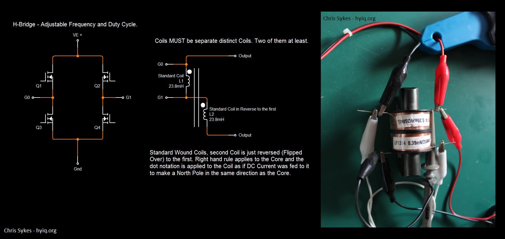
No, I'm not kidding, you should check the wire connecting the two coils, in order to have opposing magnetic fields...
@All Readers - This is absolutely correct!
You have to think Backwards! Use the Right Hand Grip Rule to make sure the Fields Oppose:
Hey Guys,
I have used this image before, here and here:
Iron Man and Iron Patriot, or War Machine, a name I dislike.
Now I want to share a Video:
Lets stop for a minute, think about the Action shown. Two Balls Fired at each other, in slow motion so you can see it.
Standing Waves, they are the same exact thing as we see, but Electromagnetically, two Magnetic Fields slapping together with a Force! A Force, Time Rate of Change of the Magnetic Fields is Electromagnetic Induction! Creating a Voltage!
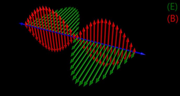
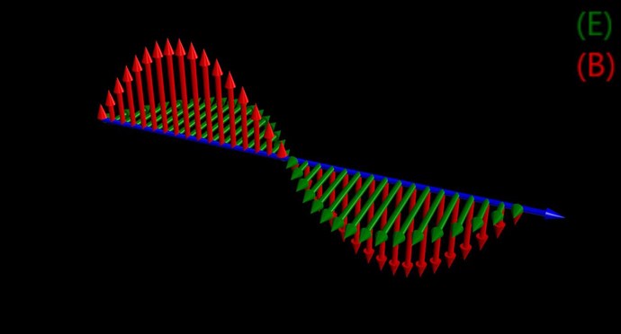
Our Partnered Output Coils work together, Oppose, to do exactly as the Balls fired at each other, or Iron Man and Irom Patriot were doing, a Standing Wave:
Standing Wave:
Electromagnetic Wave:
This Standing Wave is the result, the addition of, two separate Waveforms, each travelling in the opposite directions, as indicated above, both in the Video and in the Image of Marvels Super Hero's.
Note the direction of the Blue Arrows:
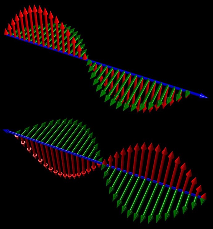
Many times on this site, we have been through the above image, but I ask you:
Think Magnetic Resonance!
If the directions of the two signals are such that opposite H-fields cancel and E-fields add, an apparently steady E-field will be created. The energy density of the fields remain as calculated above, but the value of the E-field will double from E / 2 to E.
Ref: Floyd "Sparky" Sweet
The E Field is the Green Arrows, the Red Arrows are the Magnetic Field, they sum to Zero, Equal and Opposite, shown above. Again, please notice the E Field has doubled:
Again, here:
And, remember this image? From Here.
Again, The Mr Preva Experiment, it teaches us this importance.
I am sorry for rambling, but I think its important to bring up at this stage.
Chris
I posted some data here, notice the title: Akula0083 30 Watt Self Running Generator ( April 16, 2014 ):
Remember, if you don't have Opposing Magnetic Fields, your machine will never ever work as is supposed to!
I hope this helps!
Chris


No, I'm not kidding, you should check the wire connecting the two coils, in order to have opposing magnetic fields it should connect the wire end from the outside of one coil with the wire end from the inside of the other coil, like this (link to larger image here):

I don't know the winding directions of the two coils there but you should try to change how that wire is connecting the two coils while checking with a compass or something similar (like I shown in the previous post) to make sure at the top of the Metglas you have two North poles opposing each other and at the bottom of the Metglas two South poles opposing each other.
'Cause from what you described right now the two magnetic fields seems to be attracting not opposing.
That MOSFET seems okay.

lols, thanks but my cores seem too ignore your sence of humor ?. - they want too attact irrespective of the wire direction ;=)
umm ?. am i missing something ?. - btw.
https://www.aliexpress.com/item/32820322815.html?spm=a2g0s.9042311.0.0.40ba4c4d25WqU3
i skimped on my cores, - and you should know, i have always had a good run with cheap transistors from ebay and ali express. without any observable problems ( i heard stories of FAKE RF transisitors,years ago, - but ive never personally had any problems, -- so i ordered some of these 250N's a last week, il let you know how they go ;=)
Hi Patrick,
Try to get some IRFP250N MOSFETs if possible, they worked well in harsh conditions and high frequencies on my side.
If you can't find these IRFP250N anymore (like it happened in my case) then find any MOSFET from IRFP250x series, I replaced the old ones with IRFP250:

Also if your Metglas cores slammed together at some point that means the magnetic fields of the coils are not opposing, they are actually attracting.
You should check if both coils are producing North magnetic polarity on their upper sides and South magnetic polarity on their lower sides like this:
Before connecting the two coils in series I wanted to make sure the magnetic fields produced by the two coils are opposing so I powered each coil separately and checked the polarity of its magnetic field (link to larger image here) :
Then I connected the coils in series and checked again that their magnetic fields are opposing (link to larger image here):
Also, the two coils have 1:2 turns ratio ? I may be wrong but from the photo the coils seem kind of having the same number of turns ?...
You Metglas core is looking good 
Thanks again guys, checkout the metglas, - it sure looks the part,
currently my transistors are not up too the job however, - im using an IRF840, more suited too dc motor control
i thought i would run a frequency sweep anyway and see what happens. - even though they are not good for much over 50khz. - as tested with a resistive load anyway. - but with the metglas. - the sweep run all the way up too 650khz. at which point the IRF 840, for reasons that are not clear. - went closes circuit, and my C Cores slammed together. - no damage, but i got lucky this time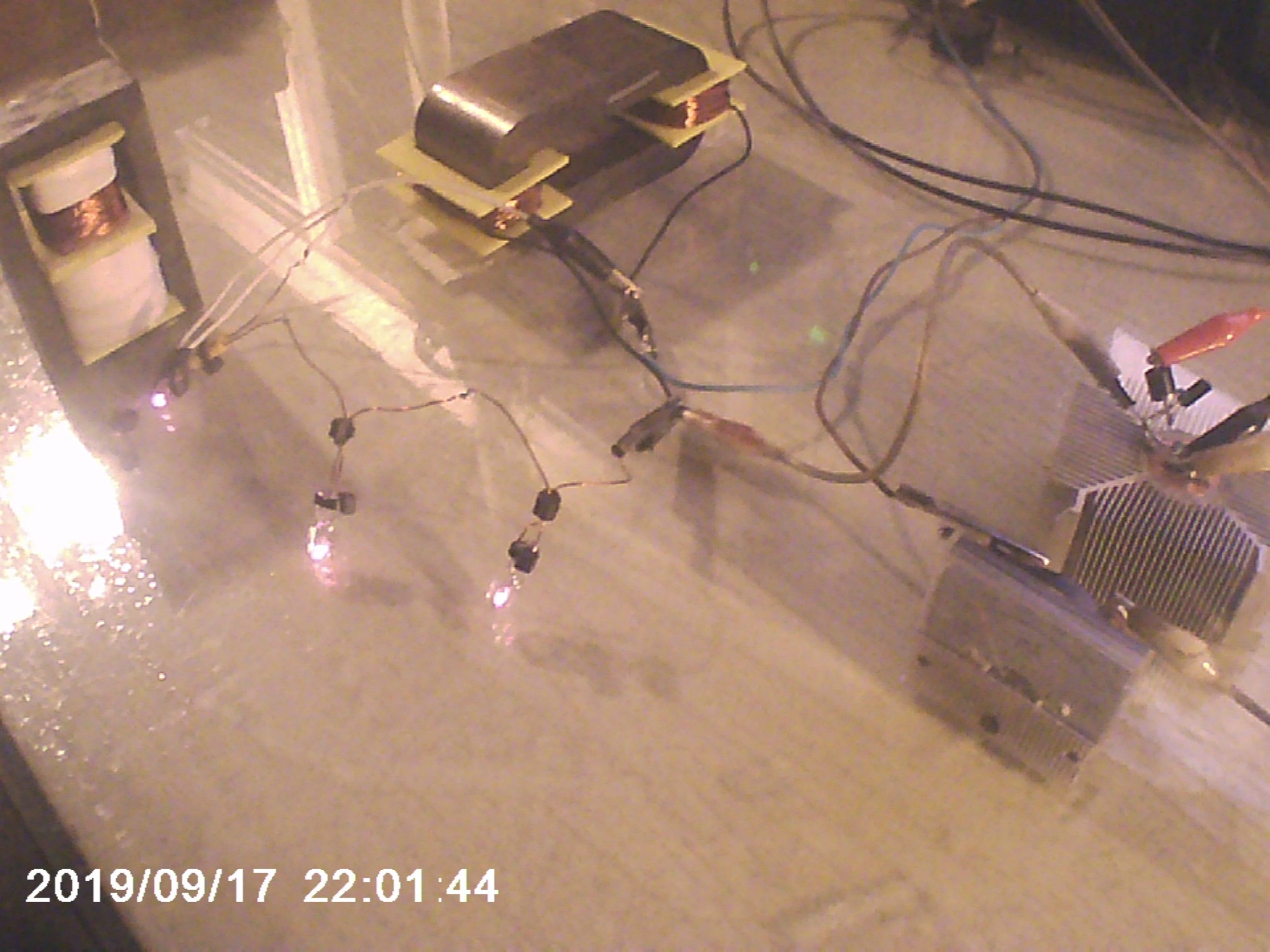
also note the ferrite in the background, 660ohms and 230ohms coils. - process of elimination for sure.
excellent, - i want have had many attempts at zpm / preva hybrids / resonant thingys. -
plan is tomorrow to go and buy some ultra thin wire, and do a low freqency resonant coil for my new ferrites. (my proper amcc 200 is lost in the mail, for another few days at least i think ;-(...
making ferrites go resonant is something i have done once of twice in the last 20years. and since im 35. i want too bloody get it right soon ;=)... let see if its this week ;-=)
one concern i have, is that a coil with like 1k resistance, and wire that thin, is obviously going too cause some problems of its own ;=D. but i really just want too suck up the knowledge like a vacuum cleaner.
IRFP250Ns are the MOSFETs I used for ZPM, they resisted a long time in experiments, just be aware in order to not damage them as it recently happened to me you should use some radiators and coolers to avoid overheating them.
Hey Solar thanks for the heads up on mosfets !!
as chance would happen i was just searching ali express for some, - since i discovered the poor high frequency performance of all of my mosfets. - even RF ones. -- which is odd ?... anyhoo...
i was about too get some IRFP250n's,,, only $35aud for 100pcs free shipping, ,even with our USD very low currently.
cheers,
I Raise my glass and chicken too akula.
that is some clever sh1t
My belief - these SiC's are going to be the "disruptive" part of making "excess energy" a reality!
I totally agree. Capability of driving high current at high frequencies is a key on the functionality of almost any solid-state overunity device (except Akula's flashlight which is using LEDs, but that's a demo device of overunity and self-sustaining device).
Fighter - another excellent SiC MOSFET. My belief - these SiC's are going to be the "disruptive" part of making "excess energy" a reality!
Thought this might be of interest:
Attached a blurb about using a free simulators with an evaluation board to better understand circuit behaviour.
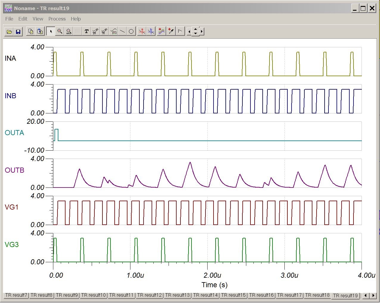
Example Schematic (SiC MOSFET Driver Evaluation Board ONLY):

NOTE the two different loads - L1 {100uH} on OUTA and C4 {100.8nF} on OUTB...
Example Results (Eval Brd only [6A max] driving L and C loads):
SL
If I may add another very fast MOSFET recommended to me by Vidura:
C2M0160120D made by Cree through its division called Wolfspeed.
https://www.digikey.com/product-detail/en/cree-wolfspeed/C2M0160120D/C2M0160120D-ND/4425548
These MOSFETs are on my list.
Hi Patrick,
Just an FYI re: transistors. Maybe review this combination (I will not recommend anything here - but we're evaluating these at the moment):
UCC21530EVM-286 [Mouser # 595-UCC21530EVM-286] - Texas Instruments FET SiC MOSFET driver evaluation board (20MHz) {driver part # UCC21530} about $50.00US;
LSIC1MO120E0080 [Mouser # 576-LSIC1MO120E0080 - Littlefuse SiC MOSFET {1200V, tr ~ 10nS tf ~ 6nS, CMOS level 3.3V drive} about $16.00US;
LSIC1MO170E1000 [Mouser # 576-LSIC1MO170E1000 - Littlefuse SiC MOSFET {1700V, tr ~ 15nS tf ~ 50nS, CMOS level 3.3V drive} about $6.50US.
Reasonable prices condisering the performance. TI's eval board is also a good deal all things considered.
Recall - dv/dt (rise/fall) can be key parameters when searching for "excess energy," no such thing, IMHO, as "too fast!" 
SL
ive been testing all my transistors for speed limits. - hmm. i need more. best i have is 2n2222 ;=D

hehe thanks for the other russian stuff by the way ... i have been listening too it on "text too speech". its great stuff
Hey Patrick - it takes time, it's like getting used to false teeth!  You'll get there, pretty sure of that... This stuff is complex; take it one "beer" at a time. [yep, false teeth - from my hockey days!
  ]
]
Heck, it took GOD 6 days but he/she kept at it by the look of things...
Another link with some more stuff:
http://www.electronics-lab.com/downloads/calculators/?page=1
SL
currently i have been trying too simplify my arrangement . my bucking coils in the mr preva configuration, show the same wave forms as chris's , however when i try too put the coils in series, across a globe, - irrespective of the polarity i just get square waves. - and too compound the issue, my scope is giving inconsistent measurements , which is not good since its my only visual learning aid.
what i will say, is that i am getting lovely flat linear power curves with my new 500gram ferrite cores. - very clean from 1-20k and tapers off from 20-45k . but i dont even know if im trying too make a tank circuit at high frequency, or a "magnetic resonance" and low frequency like preva, - i feel like... i have 1000's of dots. but no paterns.
thankyou all, but it still frustrates me that my brain is too stupid too comprehend, and while i pull my hair out, there are children without drinking water. and i cannot help. this is fu<k3d.
Hi Patrick1,
This freeware program [COIL32 and COIL64] might help also - it can calculate parameters for rectangular multi-layer cored devices amongst many other types of coils: (a good first approximation - "ball park")
SL
PS check their site for other good reference materials; for example:
https://coil32.net/theory/self-capacitance.html
Hi Patrick1,
This may be of some assistance:
[5 pages total - review pages 1 through 5; but page 3, "Parametric change of inductance in a RL-circuit. Back EMF," might pertain to your questions]http://gorchilin.com/articles/energy/RLC_3?
(as you know - select your language flag at the upper right)
Note: if your not familiar with the integral stuff (the large "S" looking math symbol) don't let it concern you - simply means look at the wave function components (U, I, L, C, etc.) over, in this case, a time period (t, or T e.g. T1, t2, etc.) [sort of like a Simpson's Rule thing - the area under the curve].
Another option is to try modelling your circuit using Micro-Cap. "Guess" if you have to at setting the initial Inductor/Transformer values (the default "ideal parameters" will probably work, initially anyway). Also, you may be able to use MC's parameter sweep and optimize functions to get a close match to your initial readings and then deviate from there.
Possibly an hour or two well spent overall! Good Luck...
Regards, SL
Hey Patrick,
Well youre on the right track!
CD_Sharp and Fighters experiments are very worthwhile! If I were you I would work to replicate their works.
Think Magnetic Field Interactions between the Coils.
1, 2 then 3, Action, Reaction then Counter-Reaction.
Put more turns on the Output.
Put less turns on the Input.
Chris
emotions aside.
thankyou so much
my conceptual issues lay in this general area.... i think if i understand what is happening. i will be able too design a great circuit from simple common components.
one issue i have is with component values. inductance's most specifically, - seem too vary alot between cores and core gapping, even with a very similar resistance and number of turns. - i am currently working with ferrite, but iron is good too. i will take any advise specific too my SITuation.
to say more, - i am very happy with my mr preva experiments, i have done them successfully many times with iron and ferrite cores. - multiple of each, including home made iron cores. ... if i could convert one of my many preva builds into a working system, i would be thrilled. - currently. the obstacles are
1; with inductive coil. - a frequency that worked with preva, seems too not look so profound when using a primary coil too induce voltages. - and furthermore, with a third coil, or primary, were getting less on the output. instead of something i can easily mistake as being slightly overunity,
perhaps i can ask instead of making you play go fish. - for eg, with a ferrite, mr preva exp, , i need too add, either one or two primaries ?,and drive it at the same frequency as preva ? and is it mandatory too do any switching on the output POCS ?
thanks for this Chris, i promise i will share the information ;=D
while you think about that. i will be trying too duplicate the mr preva bucking wave forms on my new set of palm sized ferrites... will post pictures shortly
Hey Patrick,
When you say:
a forum member willing too have a chat over the phone and share some parameters too convert my very close designs into somthing that will give me results
I want to help you, but here, not on the phone.
Let me ask you: Where do you think you need to focus, to improve your results?
Chris
Hey Guys having a depressed pragmatic day over here... forgive the intro. but i would be happy again if i could donate $100 too a forum member willing too have a chat over the phone and share some parameters too convert my very close designs into somthing that will give me results 
thanks family

Hi Vidura, thanks for the lovely comments, - in relation too the b-emf spikes. it is my belief that they are used too charge the parallel capacitor ( with the drive coil ). - which are subsequently dissipated in the coil - i think that what happens is that are dissipated in the drive coil, rather than a diode. - but its hard too know for sure, - hehe its easy too get shocks off the coil, even @ 10v... but at 800v. - i really dont know. - - once i dialed up the motor without the parallel capacitor., and it worked up too the same voltages, - but did destroy the transistors very quickly...... im still playing with all my options... quite a lot really,.. i think ;=D
Atti, i like your thinking, - at the moment the motor is critical too the funtioning of my household, - if i was not running a newman motor, i would be buy much more junk food, and have a fat arse. - so if you want too go broke, - this is the motor for you.
actaully yes, i have connected a few generators, including a F&P smartdrive ... ... they have worked ok, but i have never done a generator that is well suited too the motor, -- always much too big or much too small ;=D... - ammusingly i think a second newman motor is really going too be the best load, - but i have not prooved that yet. ;=)....... currently i am about too install a different hbridge, powered with solar panels instead of all the darlingtons and opto isolators ;=)
HERE IS VIDEO I AM TALKING ABOUT THE PROBLEMS AND SOLUTIONS.

Hi Patrick.
How do you use this machine to satisfy your household? Maybe for heating? Have you ever added a load to it?
Hi Patrick, very good your table top replication. How do you handle the BEMF spikes, are they recycled or just dissipated? Vidura.

Hi guys,
this particular newman experiment, ( the last 2 motor builds actually ). as pictured, .... were designed too figure out the importance of coil resistance.
---- and the answer is, - resistance is used too determine the rpm of the motor (along with rotor height), speaking,,, and the overall COP and torque is determined by the weight of copper (along with rotor height), !!
so basically a tall rotor gives you more torque and less speed ;=D ... and more weight in copper, aka larger magnetic field interaction will increase efficiency. one reason why joseph called his second last motor build "the big eureka" - on a semi trailer. -... and his last, a desk fan.
Hello, i thought i would take a moment out of my fiddling, and lean over too my keyboard too, -
1 congradulate chris on his video about forum etiquette
2 mention, it may be a good sign when your power supplies start behaving strangely. and powering themselves, and increasing in output voltage beyond there set levels.
...
im scared for my new scope. -- its bouncing around all over the shop whilst my power supplies are trying too blow themselves up. --------------------------------------------------------------------------
ok finally i have some idea wtf is going on, usful experiment, - giggles thankyou chris, - i am removing my "learnid" posts.
finally somthing works woop woop

this is my circuit for iron, - apparently its too complicated, but i think its perfect, thx chris. we willl see my friend ;-D
IM back on the job, after a week off on other things, - i have big ideas, ready for multiplication.
ignore this slow start. - wanted too prove of disprove, - good ideas for tomorrow, -- multiple primary's
.
Yes i agree, i have ovoided large transformers for all of your reasons, - especially because they are time consumers, and because the high power drive requirements are more troublesome.... however after putting afew days into tuning my circuit for ferrite torroids. - too remove inefficiencys of poory constructed iron transformers... - it was harder than i expected. - but now that its finished. the waves look u-beut. - 2 of them anyway....
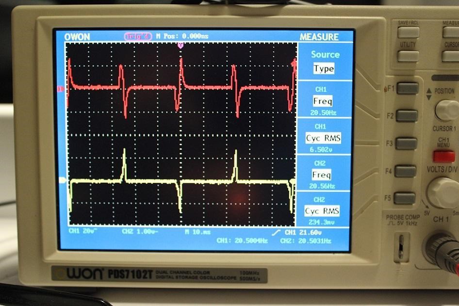
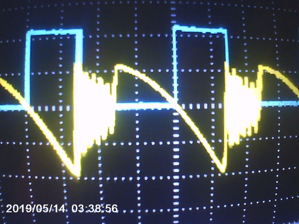
yellow is primary. , blue is trigger period of the 1st secondary. which is currently charging capacitors.. - sitll working on it,
however one bit of advise i have not used yet chris, - that i read last night, was that i should be using closer to 10 turns on my pri, instead of 100, - which i guess is true. and especially a different turns ratio. mine is 1:1. and obviously. that could be better. - especially since i have 3 transistor juntions eating 1v each. blehh..
still very promising overall, - and i actaully have a chance of beating COP1 with this setup., actually i fully expect too if i count the bemf from the primary.
the coolest thing, is that i am trying too learn a far out thing, which will take a while, - that i actually believe in.
Hey Patrick,
Re:
My efficiency has improved alot, and im beginning too understand why i have heard it said, - that for this technology, you want too use big transformers. - very big transformers.
No, not true, not yet anyway!
If you had read my posts, I say all the time, start small and cheap! The bigger you go, the MUCH harder it is to work with and the MUCH more dangerous it is.
Good experiments, thanks for sharing!
Chris
Hi Vidura, thx for the input, - " you have a very high impedance in this windings, which will limit the current and torque of the motor"
- actually i did not mention, although there are 2 coils, - they are in series, and not opposing, - too create a single large field, - which may prevent your idea from working ?. - also - yes the high impedance does limit current. - - but not torqe. -
Actually the current, according too ohms law, - (metres wont read with magnets near by). Voltage is 600v x 600ohms. = 1amp or 600watts.
but only when stationary, - when the motor is spinning @ 600v, - the input watts drops from 600watts. down too 4.5 watts. because of the generator effect of the newman magnet. ;-D

Hey Patrick1 Nice experiments you have posted . When I was watching the video an idea occurred to me, you have a very high impedance in this windings, which will limit the current and torque of the motor. Well it's just a idea, but as you have the setup you could give it a try. When the magnetic fields of the coils are opposing, you have the reduced impedance effect, almost only I2R losses. If you feed a short pulse in this configuration the current will be large, then immediately disconnect or short one of the coils ,there could arise a interesting interaction of the coils, very similar to the delayed conduction experience.Of course this needs timing, duty and RPM. Great work, Keep it up. Vidura
My efficiency has improved alot, and im beginning too understand why i have heard it said, - that for this technology, you want too use big transformers. - very big transformers. . MOT just wont cut it. although it must be said, that i have seen 10 replications with tiny transformers, and only 1 with a large transformer, - so there is alot of BS around.
Thankfully i have access too such massive transformers, from the medical industry,. - less crude than welding transformers. and still about 2 - 3kw . but i dont know if i am ready too scrap such a wonderful transformer.
anyways, this is definitely displaying LENZ free behavliour, because it is given no choice. but still only 50% efficent,
exciting project, - but im in these projects too win, so im abit anxious and it taking forever, ...
but with this one. The Suspicion was, - i am burning abit of power on the input pulse, just too long for a square wave, - so i halved it, exactly, - and the power input dropped by 66%?..., and the power output dropped by ( guessing here because its globes,). about 40%, at most.
center tap output, - globe and switch on each end.
i wonder if it matter, - weather the input coil, is in phase with the leading, or trailing, output coil.
frack 4am again, - will have too find out tomorrow,
peace and love.
interesting results, - i have the frequency @ about 10hz,
what i see, on the scope, is 2 positive offset square waves, that are each, 15 % duty cycle., - and they are touching eachother, - so basically a single 30% duty block with a color divide. .... they are the output coil.s , - and i have a third wave, positioned exactly between and overlapping the first two, - this is the input coil. .. and when the input coil, is smack in the middle , the transformer makes almost a cracking sound @ 10hz, but does not generate much light on either output globe, - however as a rotate a pot, and move the input coil backwards and forwards on the scope, from within the 1'st output coils trigger period, too the middle, and finally too fully within the second output coils trigger period, the sound alternates too a normal 10hz transformer. and produces plenty of light on each globe alternatively ,
but in the middle, where i was hoping the action would be, - is a very distinctive noise, and about 2v per globe,, so bad that it seems like the output coils are out of phase, - so i switched one of the terminals, electrically, and its twice as good as terrible, - -
btw the outputs are counter wound of course, - and fack me, i have never managed too blow a big transistor like this on 10watts, - let alone, a darlington pair, and the opto isolator via a 1k resistor - w - t - f... and the input coil isnt scary at all - its about 250turns at a few ohms.
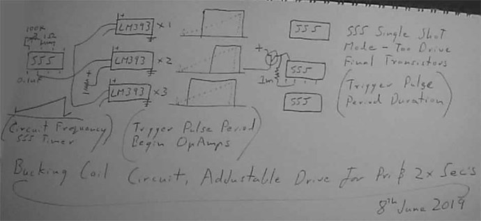
i have improved it by inserting a 4;th transtor, irf840 into the darlington, - ive upped the voltage, and still playing, - kind of scared of what the future holds, - chris;s idea about playing with arduino seems very good indeed, especially at the thought of cascading more ICS too give me negative offset pulses also, - already using 4 opamps, and 3 555's in my circuit.
lol you are correct, i work at low frequencies in every way ;-D. but after i learn wtf, evolution is the flavour of the day, - i have alot of catching up too do.
Hi Pat
If I look at the timebase of your oscilloscope it seems you work in very low frequencies.
laminated metal Core works relatively well at low frequencies.
great work and thank for sharing
jagau
wow ive had much inspiration tonight, cant wait too do some more building, but its already 3am... arrrgg. i am thinking in terms of positive offset only, square wave input, (atm)
and the first output coil. conducts immediately before the second. - however because they are wound apposing, the rebound from the first, acts too assist the second.
although it sounds simple, its something i have yet too try. - but i dont know if there is any greater gains from a particular frequency. ... yet, - i have done a napkin circuit, - i think i can trigger all 3 pulses off a sine wave, - AKA trigger each of the 3 pulses from the varying amplitude of a sine wave.
so the magnetic flux wants too collapse and reverse. but is not allowed too..
but in the case of puled dc. ( positive offset only ) . - does the negative spike play any part ?. or just let it do its thing ?
Patrick,
I still have not seen the effects. but i can imagine plenty of working theorys. - 30 of them. which is great,
i am trying to do so whilst following as fewer rules as possible.
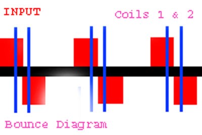
i feel the circuit it ok though,... with 555's and opamp, we can read the primary pulse. and start a timer too determine the conduction delay... and at the end of that delay, we trigger the second 555 too set the main shorting output pulse. -
diagram`ish at the very end of the video. - at this stage, i want too start looking at the actual transformer again. one i more confident in. flyback ferrite may be best, - although i did want too work with iron. @18:48
Patrick,


No one online at the moment
In physics, scalars are physical quantities that are unaffected by changes to a vector space basis. Scalars are often accompanied by units of measurement, as in "10 cm". Examples of scalar quantities are mass, distance, charge, volume, time, speed, and the magnitude of physical vectors in general.
You need to forget the Non-Sense that some spout with out knowing the actual Definition of the word Scalar! Some people talk absolute Bull Sh*t!
The pressure P in the formula P = pgh, pgh is a scalar that tells you the amount of this squashing force per unit area in a fluid.
A Scalar, having both direction and magnitude, can be anything! The Magnetic Field, a Charge moving, yet some Numb Nuts think it means Magic Science!
Hello my children. This is Yahweh, the one true Lord. You have found creation's secret. Now share it peacefully with the world.
Ref: Message from God written inside the Human Genome
God be in my head, and in my thinking.
God be in my eyes, and in my looking.
God be in my mouth, and in my speaking.
Oh, God be in my heart, and in my understanding.
More than anything else, your contributions to this forum are most important! We are trying to actively get all visitors involved, but we do only have a few main contributors, which are very much appreciated! If you would like to see more pages with more detailed experiments and answers, perhaps a contribution of another type maybe possible:
They REFUSE to tell me why!
The content I am sharing is not only unique, but is changing the world as we know it! Please Support Us!
Thank You So Much!

Ere many generations pass, our machinery will be driven by a power obtainable at any point of the universe. This idea is not novel. Men have been led to it long ago by instinct or reason. It has been expressed in many ways, and in many places, in the history of old and new. We find it in the delightful myth of Antheus, who drives power from the earth; we find it among the subtle speculations of one of your splendid mathematicians, and in many hints and statements of thinkers of the present time. Throughout space there is energy. Is this energy static or kinetic? If static, our hopes are in vain; if kinetic - and this we know it is for certain - then it is a mere question of time when men will succeed in attaching their machinery to the very wheelwork of nature.
Experiments With Alternate Currents Of High Potential And High Frequency (February 1892).