Parametric oscillations and standing magnetic waves

  • 3.7K Views
  • Last Post 13 December 2019
Vidura posted this 27 September 2019

Hello Friends. A short introduction first. I had some communication with member YoElMiCrO, initially for a different subject. As Fighter has shared his ZPM device, it called his attention, and he began to do some tests and elaborated a theory. We started to exchange Ideas and discuss the matter. I wanted to say in this opportunity that YoElMiCrO is an experienced EE and more than that he have an open mind to think outside the box as well. As he is very occupied lately, and for languish preference I will do the edition, with his agreement of course. In this thread we will share some results of tests, and also discuss the underlying theory.

Vidura

Order By: Standard | Newest | Votes
Vidura posted this 27 September 2019

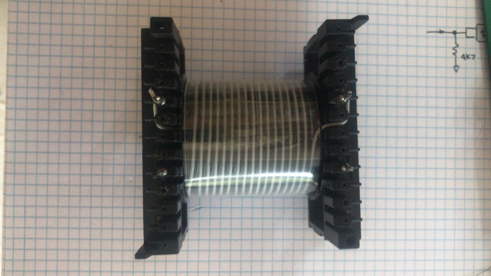
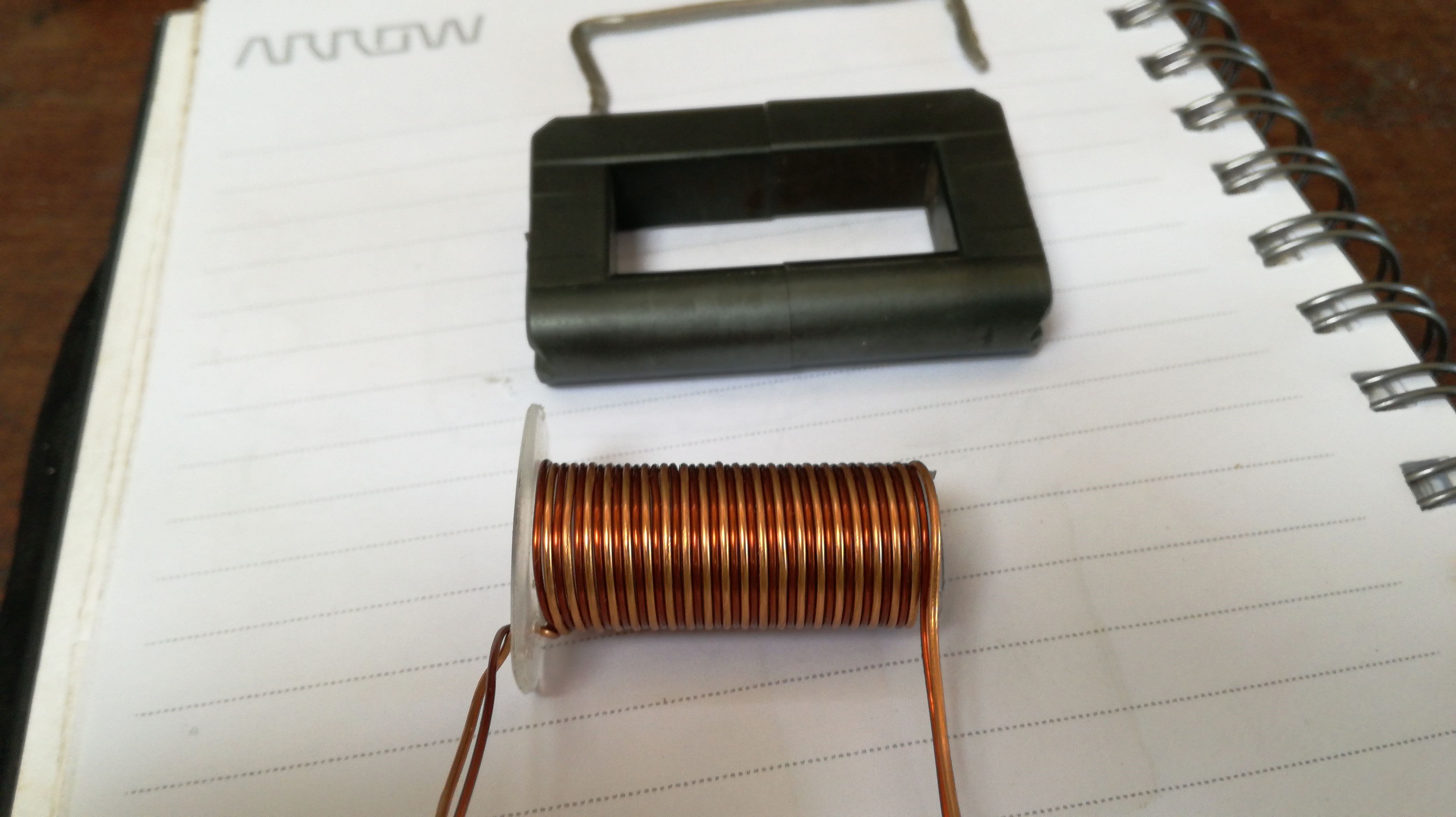
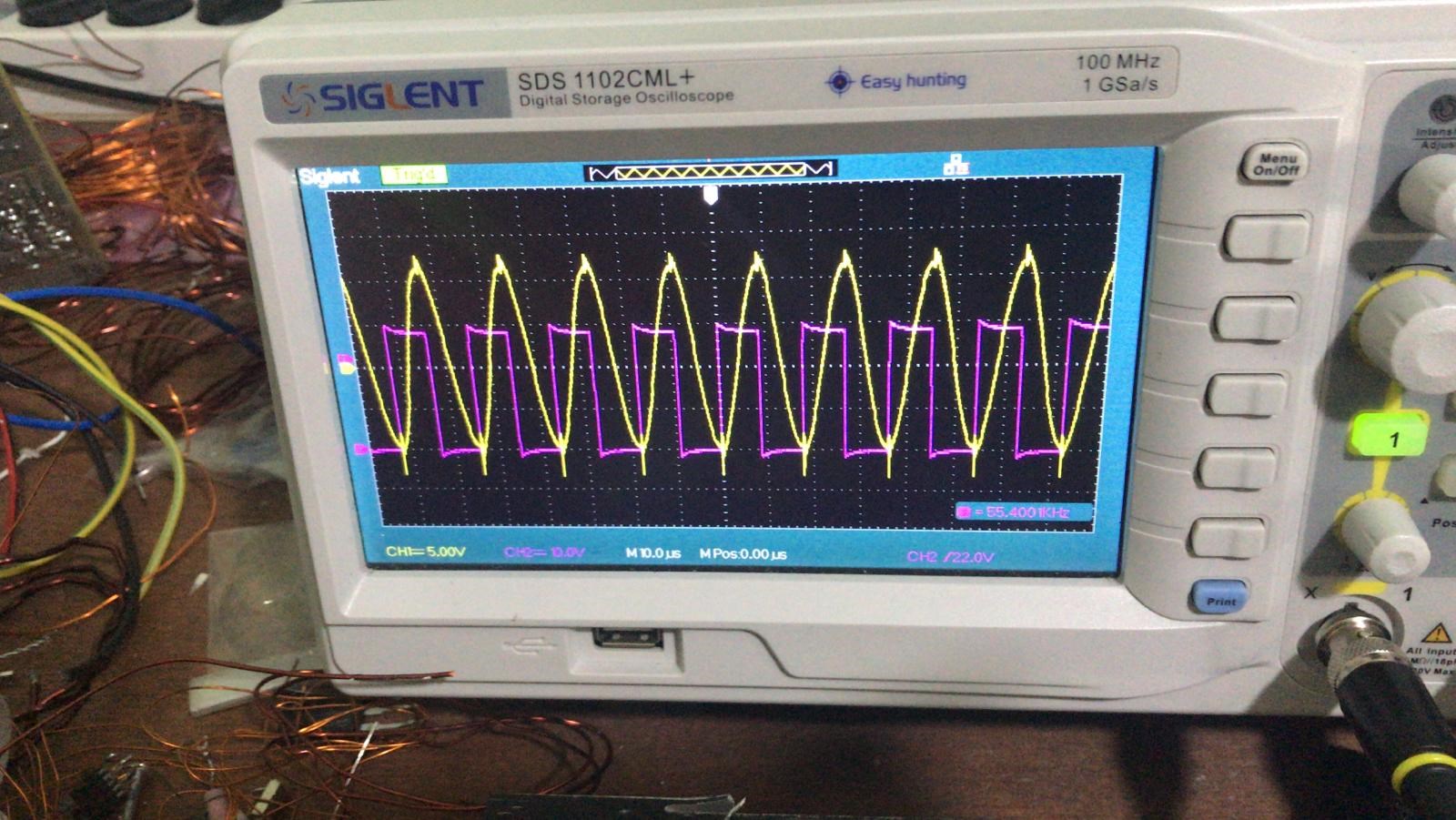
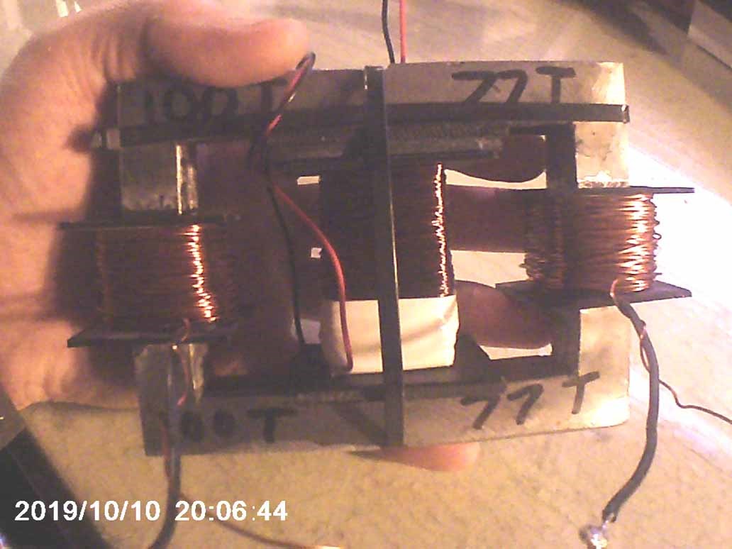
We was taking about the presence of BEMF in non inductive coils, witch I have shown in this experiment here , and some ideas for further tests arises, YoElMiCrO suggested me to do the following experiment. It consists basically in a transformer with a non inductive primary, bifiliar wound on a ferrite core: 

My replication is a bit different, with  recycled materials :

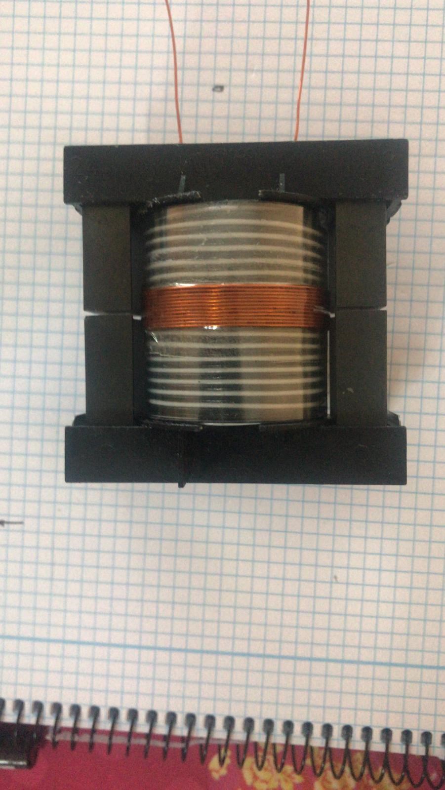
The secondary, for the moment for monitoring purpouse is wound over the center part:

In the built from YoElMiCrO the secondery is in stepdown 1:10 to avoid excessive high voltage.

Non inductive primary, an impossible transformer?

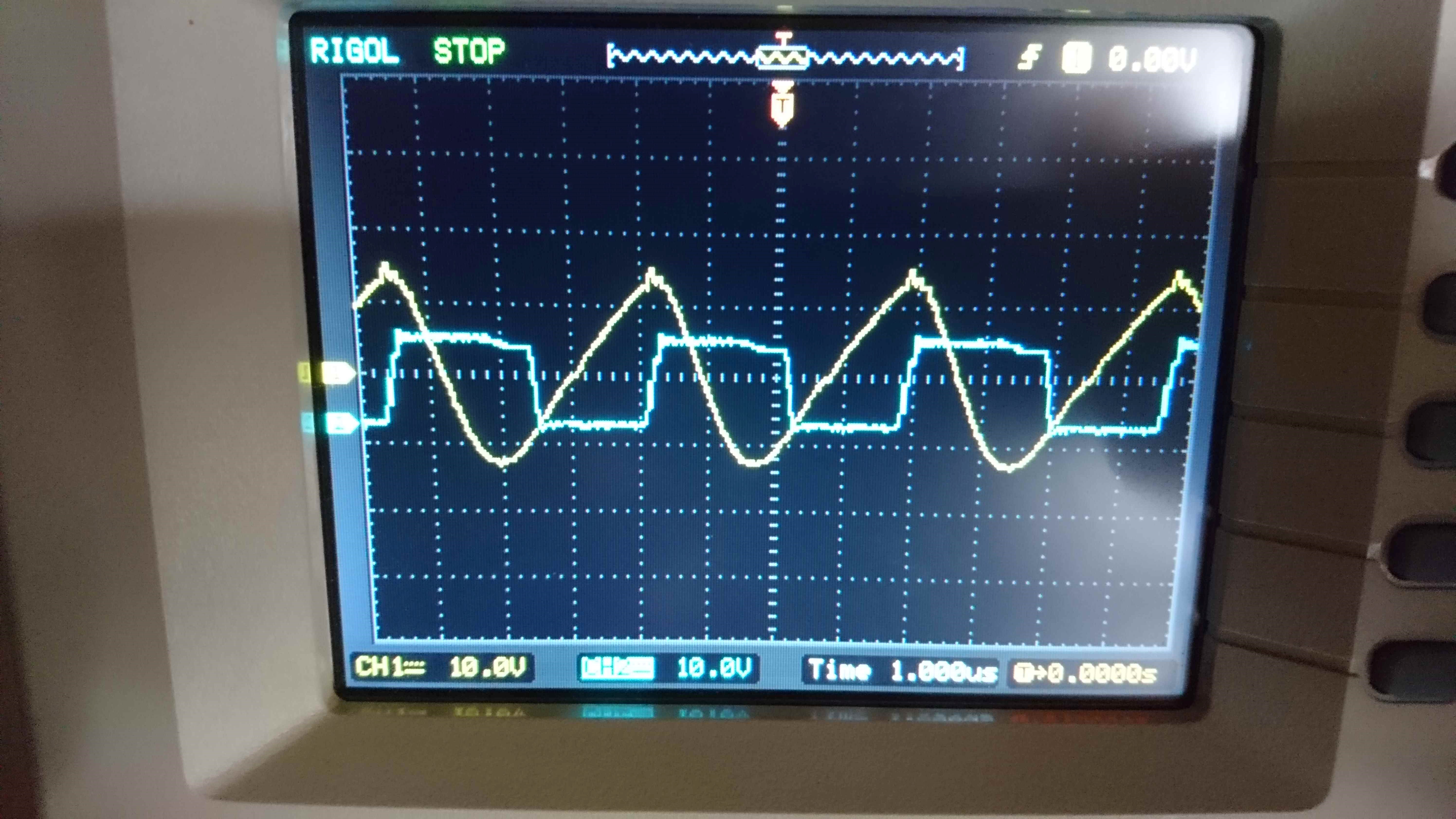
Here a scopeshot from his setup:

Note the alignment of the signals, this is important to have longitudinal oscillations.

Will continue soon.

Vidura posted this 02 October 2019

Here is some additional information: I have already made several of this coils, in summary the easiest way seems to be the asymmetric bifiliar device, using the calculation with the SQR wavelength ratio the resonance between the coil sections appears automatically. YoElMiCrO has stressed many times that there have to be an E field in order to set up the magnetic field, that in reality both are the same, like Yang and Yin two complementary parts. Here is the video:

Vidura posted this 27 September 2019

YoElMiCrO have posted some time ago in the ZPM thread the following formula to get the correct relationship between the coils:
@Fighter.
I still do tests to understand your experiment, but everything has to do
with magnetic permeability and standing waves.
The turns ratios must be quadratic because the inductance is.
This means that the turns ratios will be the root of 0.75, 0.5 or 0.25 of lambda for
one of your inductors N2 = SQR (n) N1, where n is one of the previous numbers.
Thank you all in advance.
YoElMiCrO.
The Two opposing coils have to be in one of this relationships because the coils acts as antennas, and have to been tuned for quarter wave resonance. This leads to a standing magnetic wave in the core, and to a huge rise in potential.
In my poor mathematic knowledge I asked why the square root, and not simply a relationship of turns or wirelength of 0.25 0.5 or 0.75 ? The answer is because it is a derivation of this formula: N=SQR(L/Al). Well the most important thing is that it works, and it can be replicated by anyone. The effects are very prominent, take care of your equipment when you make a replication. The good news are than basically any core can be used, although some performs better than others, the same applies for the switching. Most important is resonance, and we can use very short pulses of a quarter wavelength. If we use separated coils also the positioning on the core has to be accurate, but in the following tests with ferrites we can see the effect is present with bifilar wound coils. Please understand that it will take me some time to edit some video sequences and to order the images of the test.

Vidura posted this 27 September 2019

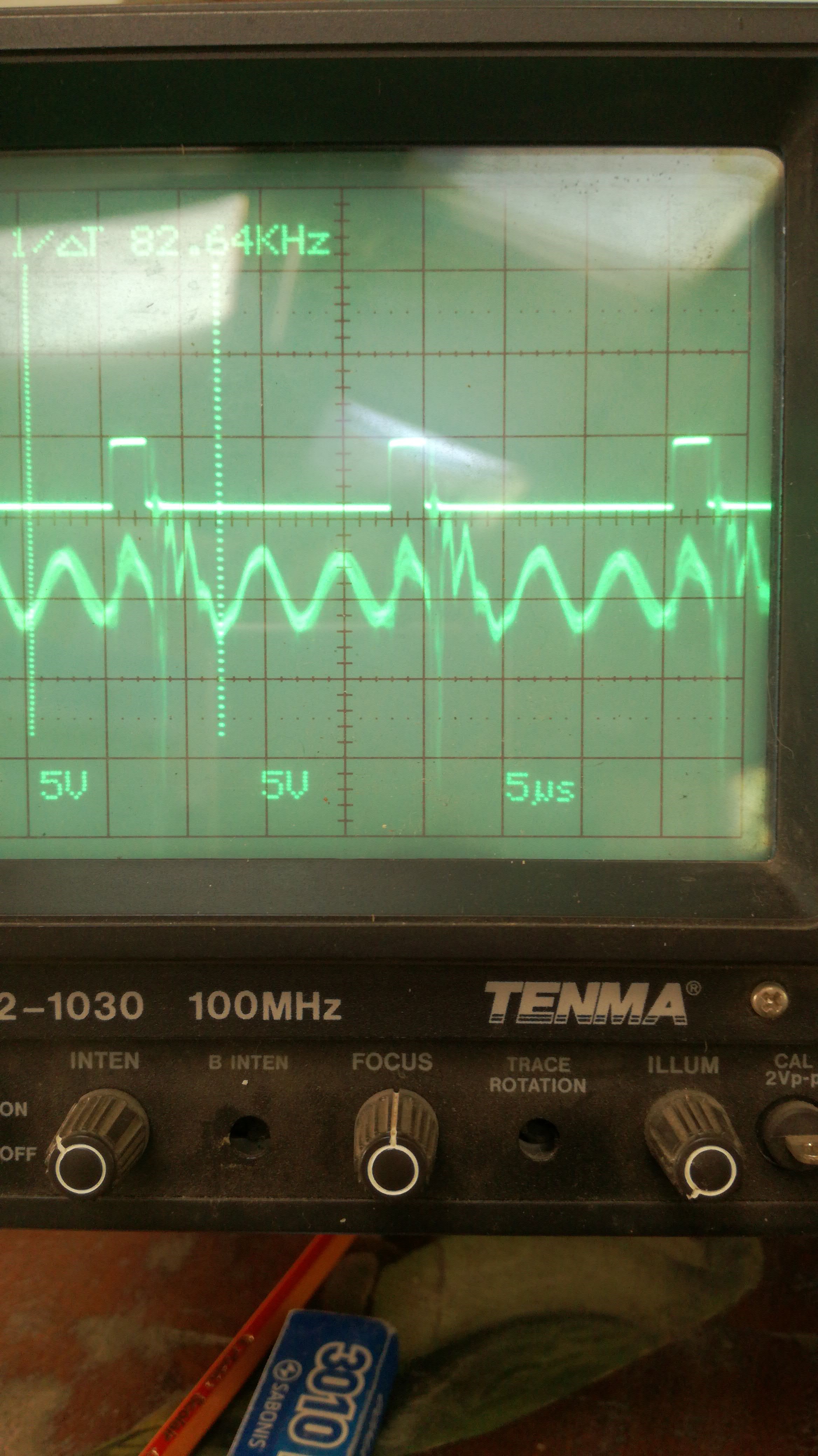
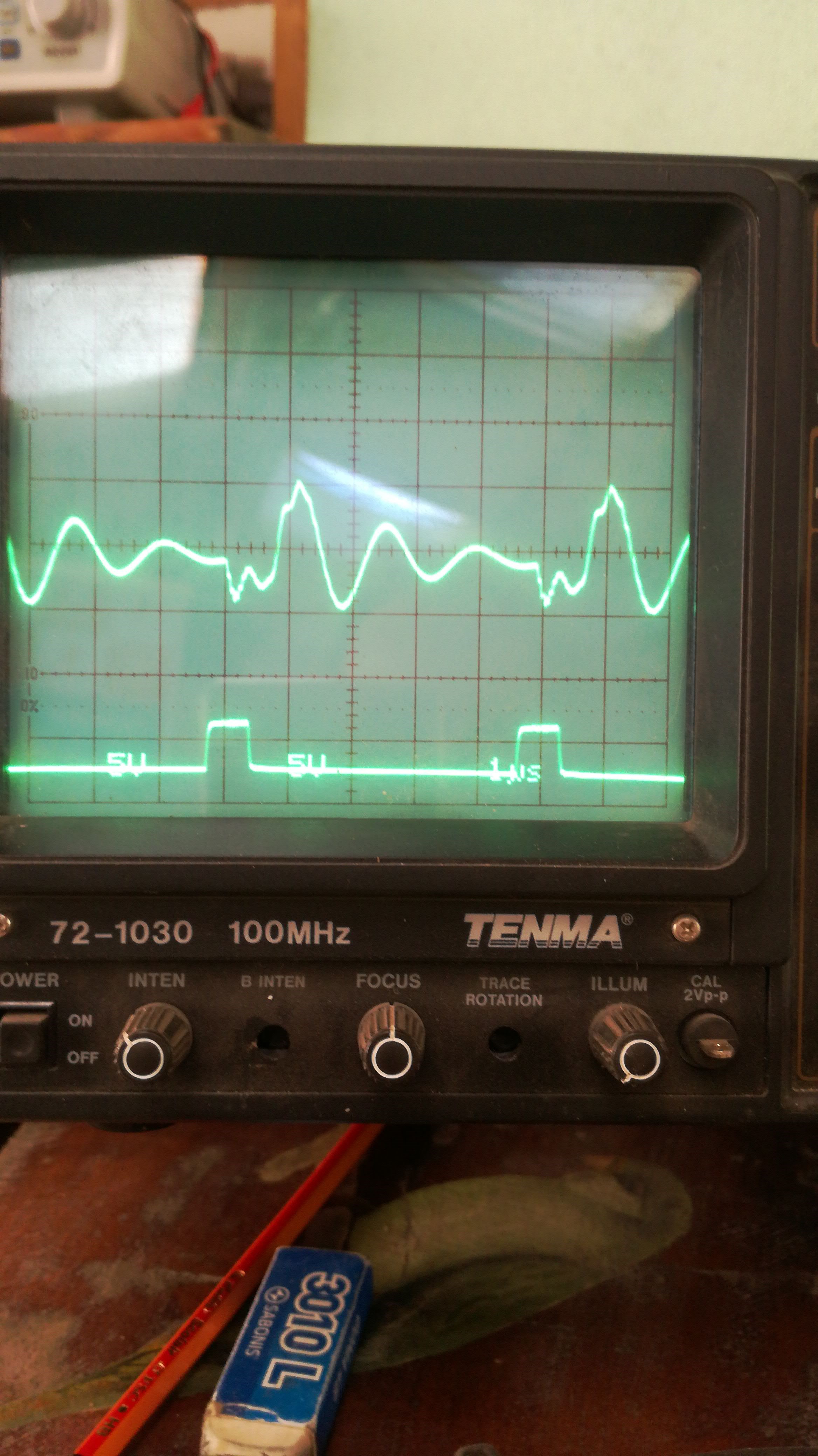
In the device of YoElMiCrO he uses a complete noninductive primary, so there is no magnetic coupling, the emf of the secondary is induced purely by the E-field. I tested first noninductive, and then i removed 3 turns from the 21 on one side of the bifilar. Here some scope shots of my results, I will add more documentation as i have time to do so.

noninductive, IGBTswitch

with a SIC MOSFET 

after removing the 3 turns

Probe factor 1:10    100V pp  with an input of 5V 10mA

will continue...

Vidura posted this 03 October 2019

@ Wistiti I have asked some questions regarding this matter to YoElMiCrO, It seems that geometry of coils don't matter, only the relationship of turns. He much more knowledgeable than me regarding calculations, when he comes back from journey we will come back to this and clarify some aspects. @All Here I made a video from a comparison with half wavelength configuration:


I also tested the quarter wave coils, and the results was that the EMF and the E-field becomes even weaker, so I didn't another video. But when we think about the reason it is straightforward, because the E-field results of the opposing magnetic field of the coils, and the opposing portion is less in the halfwave 70.7%, and in the quarter wave only 50%. Compared with 86.6% in the 3/4 wave configuration. This is of course only my interpretation, but it is consistent with the results for the moment. Regards Vidura.

Vidura posted this 10 October 2019

Hey Friends, First I was not sure to put this video in the thread , as I could not get the trace we could see on the last experiments, where the polarity is swapping abruptly when the switch turns off. Anyway the magnetic resonance is there, the standing wave produced by the opposing fields of the nearly identical coils. And the effect of the E-field is stronger than in other devices. Here is the video:


Sorry about the mistake in numeration, number 3 already was poste, it should be nr4.

Vidura.

Wistiti posted this 24 October 2019

Hi YoElMiCrO and all. So with the formula you share , is there a simple ratio we can use for newbies? Something like 1 turn for 1,9 turns on a same core?

The kind of easy way as everyone can easily try..?

Thank you!

Vidura posted this 28 September 2019

@All Please note that on my replication I am not in direct resonance, it is driven at a lower harmonic. When I made the coil I was not aware that YoElMiCrO used much more turns, 130 bifiliar, so his frequency is much lower, more convenient for ferrite to keep it below 200khz. So I will correct the coil before continuing with other experiments. Vidura.

Vidura posted this 29 September 2019

Hello,

as i had some time today i made another coil, this time more similar to the one shown by YoElMiCrO, with another fly back core that i got from a friendly TV repair technician. All the tests shown are made with a noninductive bifilar primary coil, I still did not try the quarter wave technique, this for the next testing series. I can tell you ,this device is really mind boggling.

I wanted to add that this time it was possible to drive the device in direct resonance, but at expense of increased current drawing(reduced impedance). and as the wires are thin to avoid heating I used a lower harmonic again.

VIDURA.

Vidura posted this 30 September 2019

Hey Hopeful1,
I did as many tests as ocurred to me at that moment, certainly it would be interesting to test different loads, secondary windings and so on. Time is limited and everyone who would join the research on this device could add important information, and would be welcome. It is a simple device, cheap and a lot can be learned. I have not seen this behavore before , it could bee a feedback effect or changing impeadance of the antenna system, in my guess.

Vidura

Chris posted this 02 October 2019

My Friends,

This thread is fast becoming one of the most important here at aboveunity.com!

Vidura, you're a very wise man, your work, experiments and effort to share is very much appreciated! All here can greatly benefit from these experiments!

My thread: How to build your own Above Unity Machine, will now be much more clear for all that are following and doing the experiments with Vidura!

It is amazing, we have such progress, its fantastic to see!

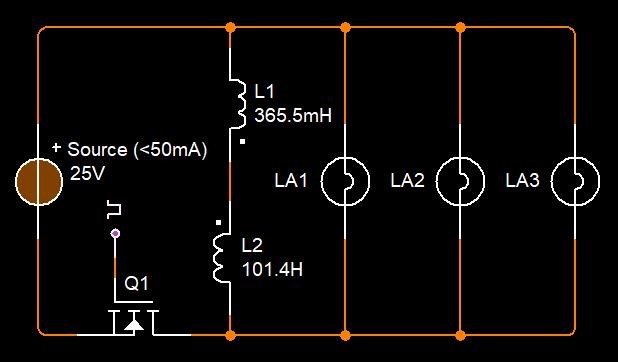
I suggested another thread, one with hard data, some .NET Apps to calculate the turns and so on, but this thread is already that. Remembering Fighters Schematic:

R coil has 365.5mH inductance and approx. 300 turns made of 0.8mm standard copper wire for coils. These are the complete characteristics I measured with my LCR meter (link to larger image here):

Ref: Fighters original Post.

// Turns:
double L1Turns = 300;
double L2Turns = 0.0D;

// Wave Types:
double QatarWave = 0.25;
double HalfWave = 0.5;
double ThreeQatarWave = 0.75;

// Chosen Wave:
double Lambda = QatarWave;

// Do Math:
L2Turns = Math.Sqrt(Lambda) * L1Turns;


L2Turns = 150 turns. Which is correct:

L coil has 101.4mH inductance and approx. 150 turns made of 0.8mm standard copper wire for coils. These are the complete characteristics I measured with my LCR meter (link to larger image here):

Ref: Fighters original Post.


I ask, all readers, join in!

Don't be shy, I will protect all, none get trolled here! All Members are important to me and I will not allow any harassment!

Of course, thank you to YoElMiCrO, I did not know about the equation given!

best wishes,

   Chris

Chris posted this 03 October 2019

Hey Wistiti,

An excellent question!

Turns ( N ) on the Core are the formula's result. See my edited Post here.

However, Inductance ( L ) is directly related to the Turns ( N ), as you know. So, one equation to calculate the Inductance ( L ) is:

L = N Φ / I

Where:
       L = Henry's
       N = Number of Turns
       Φ = Magnetic Flux
       Ι = Amperes


So, this simplified equation is Turns ( N ) multiplied by Phi ( Φ ) / Amperes ( Ι ), most definitely a strange way to find the value that is Inducted... 

NOTE: Ampere Turns NI is also related, this is the M.M.F, Magnetomotive Force.

See our thread: Non-Linear Inductance, as this does explain a lot more!

I have a small calculator I am working on, for a few small, simple equations that for some would be difficult to implement outside a Calculator. I will work on this and see if I can make it useful enough to post soon.

   Chris


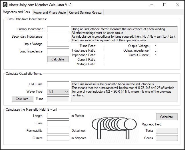
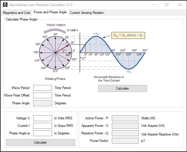
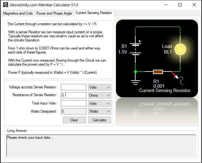
EDIT: Calculator attached as Zip File: "AboveUnity.com Member Calculator" - Early Version, please ask for changes and improvements!

Attached Files

Chris posted this 04 October 2019

My Friends,

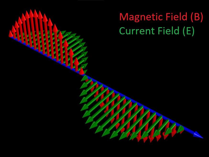
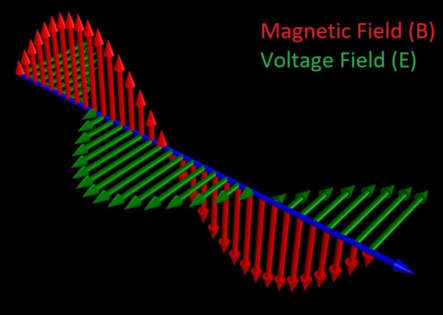
Regarding the E-Fiend, if we consider the E-Field as Current instead of Voltage, then we vat an almost exact 90 degree difference on the Cartesian Plane:


Remembering, in a Resonant System, Voltage and Current ae normally around 90 degrees out of phase, so a System where Voltage is considered the E-Field would look like this on the Cartesian plane:


So, we can see there is a big difference between the definitions visually.

Remember, we are dealing with the same thing, its an ElectroMagnetic Field, the Vectors are different for each entity, that's all!

One Entity, but two Vectors.

The E-Field is always present!

The Magnetic Field is always present!

The Time ( t ) at where we observe the Fields, E and B can be different, as each entity can Transform in a Resonant System, thus the shown Phase angle differences shown above.

Vidura, this thread and your experiments are invaluable, thank you from the bottom of my heart! This is such a usefull thread!

I urge all Join In!

   Chris

Chris posted this 04 October 2019

My Friends,

YoElMiCrO and Vidura's work, to understand Fighter's work, is very important!

Lets take the following Experiment:

A Single loop of wire, the length of a single loop is: 111mm and we have 100 loops the same length.

Our 100 loops at 111mm each is equal to N1.

Our equation:

N2 = SQR (n) N1

Ref: YoElMiCrO


So, calculating: N2 = sqrt(0.25) * 100 = 50 loops at 111mm each.

Now comparing:

  • N1 = 111 x 100 = 11,100mm.
  • N2 = 111 x 50 = 5,550mm.


For Half Wave: N2 = sqrt(0.5) * 100 = 70.71 loops at 111mm each.

  • N2 = 111 x 70.71 = 7,848.81mm.


For Three Quarter Wave: N2 = sqrt(0.75) * 100 = 86.6 loops at 111mm each.

  • N2 = 111 x 86.6 = 9,612.6mm.


Now, if we look at the length of the wire:

  • 11,100 / 2 = 5,550mm = 1/4 wave, which is what we calculated for N2.


Respectively, we can get: 

  • 11,100 / 1.414 = 7,848 = 1/2 wave.
  • 11,100 / 1.154 = 9,612 = 3/4 wave.


The Frequency ( f ) = 27.00 MHz

The Speed of Light ( c ) = 299,792,458 meters per second

We know, for an Antenna, a Half Wave is the optimum Wavelength to transfer Electromagnetic Energy, this is: λ / 2

Where

  • Lambda ( λ ) = the Wavelength at Resonance.


Which means:

  • Lambda ( λ ) = Speed of Light ( c ) / Frequency ( f ).
  • Lambda ( λ ) = 299,792,458 / 27,000,000 = 11,103mm
  • 11,103mm ≅ N1
  • 11,103mm / 2 = 5,551mm
  • 5,551mm ≅ N2 calculated above ( N2 = 111 x 50 = 5,550mm


Remember this:


This, in combination with our Antenna Theory threads, here and here, with the thread here and here, means we have a lot of very special logic to study!


The Coils become Resonant at the Half Wavelength, which is calculated by the Quarter Wavelength of 0.25. This is using the Inductance, but means the Wire length of N2 is half that of the N1 as seen in the above Experiment, which is Lambda ( λ ) / 2.

However, please remember, this is only one way, many ways exist to get to the same goal! We are specifically referring to Fighters work in this thread.

   Chris

Atti posted this 06 October 2019

Chris,

I understand what you're saying.

Thanks to Vidurra for sharing her detailed experiment and work.
I managed to create magnetic resonance.

What was important for the setup:
- frequency,
-FET fill factor
power supply voltage
As well. The FET (IRF540) used on the first try worked perfectly. I managed to adjust the magnetic resonance. I used the same number of turns as Vidra. (70.5-61T)
Grounding is really not necessary.
I also tried other transformer arrangements.
Magnetic resonance can also be perfectly created there.
But the voltage was higher, so the FET broke down.
I replaced it (2SK2655) but unfortunately I couldn't adjust the resonance.
 (Here you can see the importance of fast FET on / off and low gate resistance.)
I replaced the FET switch again.
Unfortunately, the timing drive circuits have now been destroyed. Not just the FET switch.
So let's take a moment to try again.
But I managed to take some pictures.
Anyway.Now I know what I'm looking for.


The high voltage also appears on the ferrite transformer. This is shown on the phase search pencil.

Jagau posted this 07 October 2019

Hi Chris


You are right, for more precision see page 28 of this book that I already published

N is for computing turn and Al  is inductance factor  

@ fighter
I have experimented the ZPM but with ferrite and it function very well

I will publish in time results on your very interesting thread

Jagau

Attached Files

Jagau posted this 08 October 2019

Hi all

This is a very good advice from FLOYD SWEET that I use with my ferrite.


Dixiit Floyd Sweet from magnetic resonance


For this machine to work, some means would have to be formulated to instantaneously vary the frequency to match varying load impedances. Surely a most challenging task. First, the capacitor should be removed and the inductor designed with sufficient distributed capacitance to prove integral LC. Then calculate what frequency will resonate the R.C.L. network. This will not cure the impedance problem, but will provide a more stable experimental set-up


Jagau


Jagau posted this 08 October 2019

Hi Vidura

At the same time I will have a question to ask you about the equation of YO which is N2 = sqr (n) N1
I do not understand at all where and how does this equation work?

I know that to find quarter wave (.25) half (.5) and three quarter (.75) wave how to do but it's the SQR that I do not understand.
Maybe to ask YO ??


Its quadratic expression could mean that there are more solutions

as in the case of a parabolic response ??   I do not know
thank you for taking care of it


Jagau

YoElMiCrO posted this 09 October 2019

Hello everyone.

I'm traveling, that's why I couldn't be active. When I'm back I update and continue with the experiments.

YoElMiCrO.

YoElMiCrO posted this 18 October 2019

Hello everyone.

I have seen all the posts from where I left before traveling.
Good experiments for everyone, with such a community we will achieve
show that it is possible AU.
I take this time window to see where it derives from N2 = SQR (3/4) N1.
From my point of view, it turns out that we cannot treat MRI
as if it were a physical antenna, this is because they are the inductances themselves
those dealing with such resonance.
We know that at ¼ length in time the maximum value for a voltage occurs
sinusoidal and as inductors in this case are those that deal with the electric field
while current flows through them, it will be these that we will modify.
Remember that N ^ 2 = L / AL.
So…
If L2 should have the value of L1 * (3/4).
Step by Step…
L1 = 1mH
L2 =?
As the bounce of the standing wave at its maximum occurs at ¼ then
L2 should be 1- (1/4) = 3/4.
AL for equal convenience 1
Let's calculate using the formula for inductance.
N1 = SQR (1/1) and will be equal to 1Turn.
But L2 should have an inductance equal to 0.75mH.
Again…
N2 = SQR (0.75 / 1) and will be equal to 0.866Turn which is the same if
N2 = SQR (0.75) N1.
This is how the formula derives.

Any questions let me know ...
Thanks in advance.

Chris posted this 19 October 2019

Hello everyone.

@Zanzal.
I still keep it as a hypothesis since there are many gaps left to cover.
The basis of the hypothesis is as follows.
For decades physicists gave names to the entity we are looking for.
Those names were, Ether, ZPE, Quantum Void, Sea of Dirac among others.
We know that from somewhere we have to extract energy to finally achieve AU.
From my point of view this entity is only the electric field.
I explain...
In any transformer with two inductors formed by N1 and N2
under pulse work regime, (E) is always present.
We don't have to wait to generate any magnetic field.
From the moment we apply the pulse to one of the two inductors, say N1, it will appear
a voltage in N2 that will be V2 = V1 / (N1 / N2) as we all know.
If we leave the voltage V1 to N1 applied, we will start to use energy from our source
supply due to the magnetizing inductance N1 that will move the magnetic domains
in a given direction.
On the other hand if we apply a charge to N2, then to hold the electric field
that is entering the system will also be our source of supply that provides energy.
That is what T.E Bearden refers to when he talks about not destroying the dipole, at least I think so.

This simple experiment demonstrates how to make only magnetizing energy
the supply source provides while the load current is provided by the material itself.
It is a circuit with positive feedback, in this way N2 will make a clamp to the voltage
of supply and the magnetic field itself will provide the charging current.
It is the same basis for Mr. Preva's experiment but it works in the first quadrant.
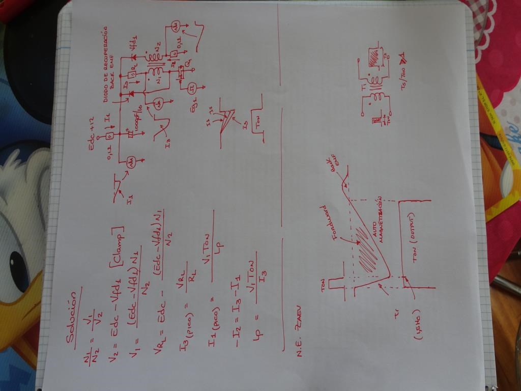
N.E Zaev also applies the same hypothesis from my point of view.
But about an inductor and the capacity of self-magnetization that the material possesses
that composes it, because during this spontaneous action the tension will continue induced
in his secondary, in his case the timeline is the one that relates the energy.
The secondary voltage lasts longer than the applied one, then the energy gain
It will be proportional to the time ((T) induced / (T) initial.

If you look, I think everything is related, the idea of ​​getting that field (E) from the middle
and the current of magnetism is what I currently pursue.
Chris is right.

Thanks in advance.
YoElMiCrO.


YoElMiCrO, I believe you have it. wink

A small Input Pulse can and does create a large Output Pulse under the right conditions.

We must all stick together, we are all one, every single human being on this planet must benefit from this! I ask all of you, try to stay up to speed on this! Learning, Building and Sharing is the only path forward.

   Chris

YoElMiCrO posted this 24 October 2019

Hello everyone.

@Wistiti.

It turns out that in the transformers it is very difficult to make turns
decimals, this is because once it enters the core
It is considered a complete turn.
There are methods to make half turns, using the posts
sides of the E-transformers, but this is not the case.
That is why the best relationship of turns would be this.
Every 7 complete turns of N2, N1 will have 7 + 1 = 8.
It is important to note that only multiples of 7 are allowed.
For example, let's say that N2 = 14 Turn is twice 7, then N1 = 14 + 2 = 16 and
so consecutively.
Then the final relationship would be:
N1 = 7n + n.
Where 7 is the smallest number of turns for N2 and n is the number of times you rolled 7 turns in N2, that is a multiplier.

I don't know if I help you.

Thanks in advance.
YoElMiCrO.

Wistiti posted this 24 October 2019

Thank you for the clarification, it is really appreciated!

So if i understand correctly N2 must be first a multiple of 7 and N1 is the same as N2 plus the number of time we have 7 turns in N2.

For example.

N2= 7 turns, N1 must be 7 +1 or 8 turns.

N2 = 14 turns (or 2 times 7), N1 must be 14 + 2 or 16 turns.

N2 = 70 turns (or 10 times 7), N1 must be 70 + 10 or 80 turns.

And so on...

Much more clear for me now!

Thanks again for your contribution!

Vidura posted this 27 September 2019

Yes Al the specific inductance factor of the core.

Zanzal posted this 27 September 2019

I question the existence of such magnetic waves in the core. But there is an experiment that can be done which should prove whether magnetism propagating is through the core like a wave. Reflection, constructive, and destructive interference should all be possible if that is true and observation of these things would prove that it propagates as a wave. So a standing wave would be possible under the correct conditions and a standing wave would be what we'd want to look for as it would be the best proof of this. Frequency would be dependent on geometry of the inductor and the speed of the wave.

It should be possible to prove this without an oscilloscope by using very small 2-3 turn pickup coils placed evenly along the length of a ferrite rod with each coil attached to a LED. Using something 9+ evenly spaced coils should give a very good picture if a standing wave forms in the core as the LED brightness would be an indication of the density and reveal the nodes/anti-nodes. The core would be excited by a coil at one end. If the LEDs show a standing wave pattern at a certain frequency we would have hard evidence and we'd also be be able to determine the wave velocity which should be much much lower than c.

Doing this with any inductor should work, as we would expect if magnetism propagates through the core as a wave than any core material (even air), not just amorphous core. Though if the experiment succeeds or fails other core types and geometries should be tested, I think it makes sense to start with a common ferrite rod. I plan to do this experiment when I have the ability (my stuff is all packed up at the moment). It is great to know others are already a step ahead on this. Makes me much more excited at the possibility the experiment will succeed.

Vidura posted this 27 September 2019

Hey zanzal, Basically you are correct, standing waves can be detected using small inductor with LEDs attached, but you have to take in account that for a standing wave two opposite traveling waves have to join. When using a ferrite bar you will get the opposite wave only by reflection at the end of the ferrite rod and in attenuated intensity. In a closed core both waves will propagate in opposing direction and "slap together" with the same intensity. Anyway ferrite is a difficult material to show this effect but it can be done. Much easier it is with Metglass, permalloy or even silicon steel (at much lower frequency). It would be great if you want to test and post your results. Vidura.

Chris posted this 27 September 2019

My Friends,

I am a very proud man, you're all awesome! I never dreamed that such effort would come to fruition based on a few simple things. 

Look at what our team is achieving! This is why we are Light Years ahead of the other forums! We have made history, every one of you are part of this!

Yup, I have goosies wink

   Chris

Vidura posted this 29 September 2019

Hey Chris , of course your videos are helpful. For me specially the latest about magnetic resonance was very valuable, as I was looking always for something magic occurring inside the core, instead of treating the coil-core assembly as unit. The earth grounding I test in most of the experiments, in this case it was obvious that something was missing, as I did not get the same result as YoElMiCrO, I use my scope normally floating without ground connection( that is why I have more ringing in the scopeshots ), this was the difference, he had his scope ground connected to the MOSFET drain.

Thank's

Hopeful1 posted this 29 September 2019

G'day vidura

Awesome work.Would you say that the increase in amplitude is in response to a greater demand on the circuit by the L.E.D.? If so would it go up even more if the demand were greater

Vidura posted this 03 October 2019

Hey CD 

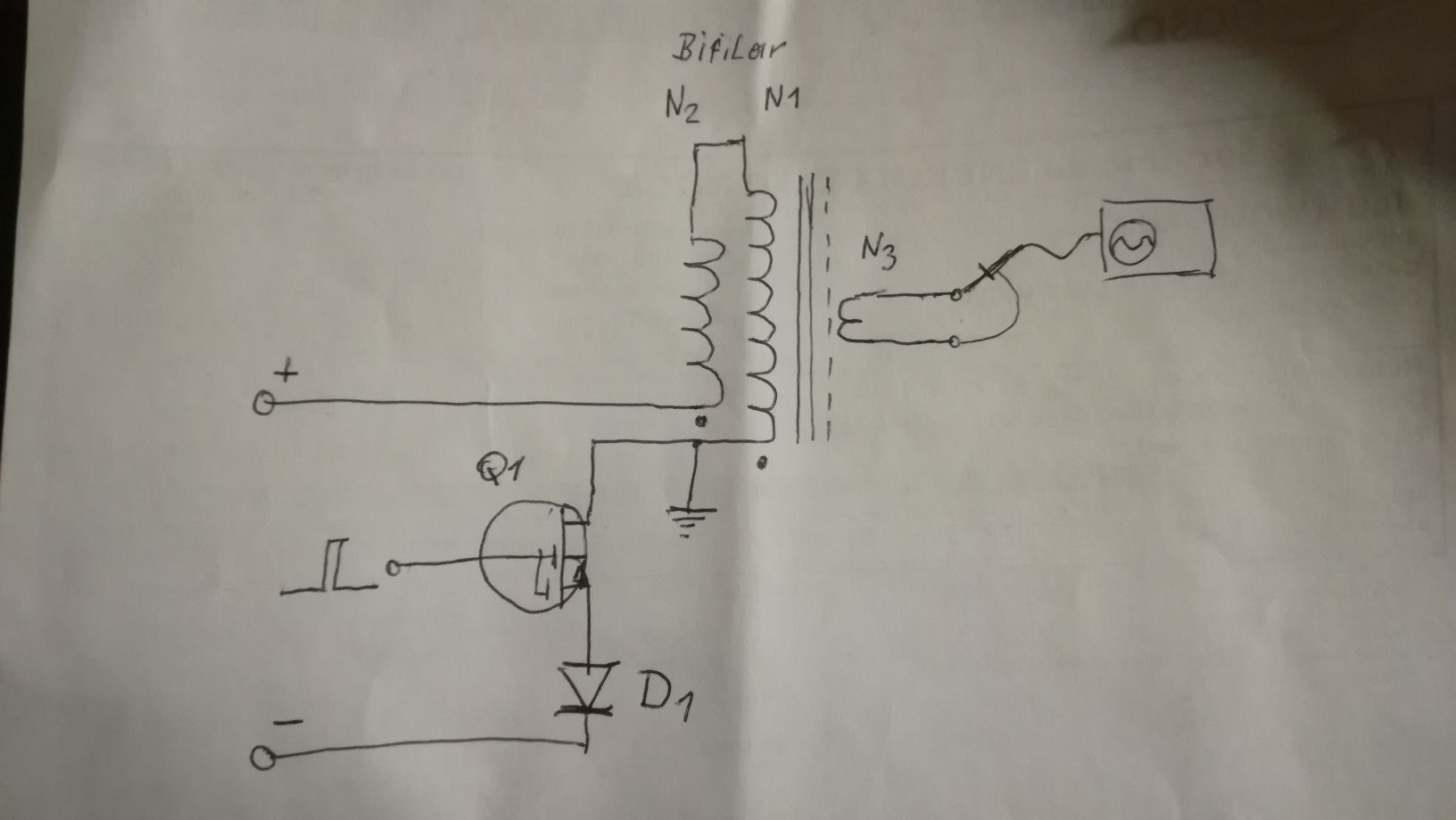
here is a sketch from the setup:

I have tested with and without D1, YoElMiCrO recommended to use it, but the oscillations are less damped without it, further tests with the  loaded device will be needed to evaluate this. Also the earth ground is not needed for the functionality of the oscillations, but it will likely add current for energy extraction. In noninductive configuration( N1=N2) only with the ground connection there was a significant EMF in the  L3. Turns N3 are 10-20% of N1, put the scope probe in 1.10 as the voltage can rise to high levels.

The wire tap on the top of the coils is the junction of the bifilar coils.

Vidura

Vidura posted this 04 October 2019

Someone has asked if there is a sinewave fed into the circuit, the answer is no, I used only short DC pulses of less 1 us. If you use a SG try to maintain this puls duration when looking for the resonance frequency, you might need to adjust the duty% according to the frequency. Vidura.

Vidura posted this 07 October 2019

Hey Chris, We can actually treat any coil as an antenna, and as a transmission line. But in my guess we have to be careful to simplify and use the same scale for a straight wire or antenna than a coil. Think about the old type of radio receivers, they used MW and LW range, an extended antenna would be very large, kilometers in LW range, so a ferrite rod antenna was used, and likely it don't have kilometers of wire wound. This would indicate that the inductance (and frequency)calculations are different as for a straight line. I think Jagau has a lot of knowledge in RF techniques, maybe he can give his opinion too. On the other hand I have observed in my experiences that there are two different resonant frequencies, there seems to be a predominantly longitudinal oscillation also, depending on the wirelenght and capacitance (open, like the TC topload), and grounding. So maybe we have to use both components and bring them in phase for a maximum effect.

Edit: what i wanted to add it that the example of the wirelength related to the nr of turns will certainly match as long as we have a single layer coil, like don smith in most of his devices, but in the multilayer coil it will differ, as the length x turn is not constant.

Regards Vidura.

Vidura posted this 08 October 2019

Hey Jagau, 

Regarding the calculations there are others more knowledgeable, but in mi primitive way to understand I would say that the inductance  value is critical for resonance, and it seems to be non linear in relation to the nr of turns of a coil. We where mostly treating bifilar coils , where geometrical factors would apply almost identically for both coil sections, and thus could be disregarded. YoElMiCrO has mentioned the influence of the length of the inductor in our communications, and we will come back to this later with more detailed explications. 

Vidura

patrick1 posted this 10 October 2019

Hi Vidura,  i have been playing with the coil inductances, i too believe this is a critical point too tuning. - although i have been testing the square root 1/4 and half wave   - coil setups. ...   i am have difficulties identifying the resonant point... there are promising looking points, when a inductance square wave, morphs into more of a sine wave, - but on my output coil  @ that point. - im not getting anything out lol.  - coupling is too loose, - but thats a diffent issue.   -      i have not seen many attempts @ tuning these machines with iron cores. - bringing them in and out of resonance. 

Vidura posted this 11 October 2019

Hi All Here another experiment, some odd things discovered accidentally.

Edit: another odd observation I made is that when i connected both terminals of the coil to the same side of the switches( halfbridge config) the intensity of the oscillations reduced to half, although the polarity, and all other parameters was the same, only with two switches less.

Vidura

Vidura posted this 19 October 2019

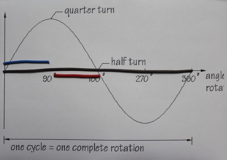
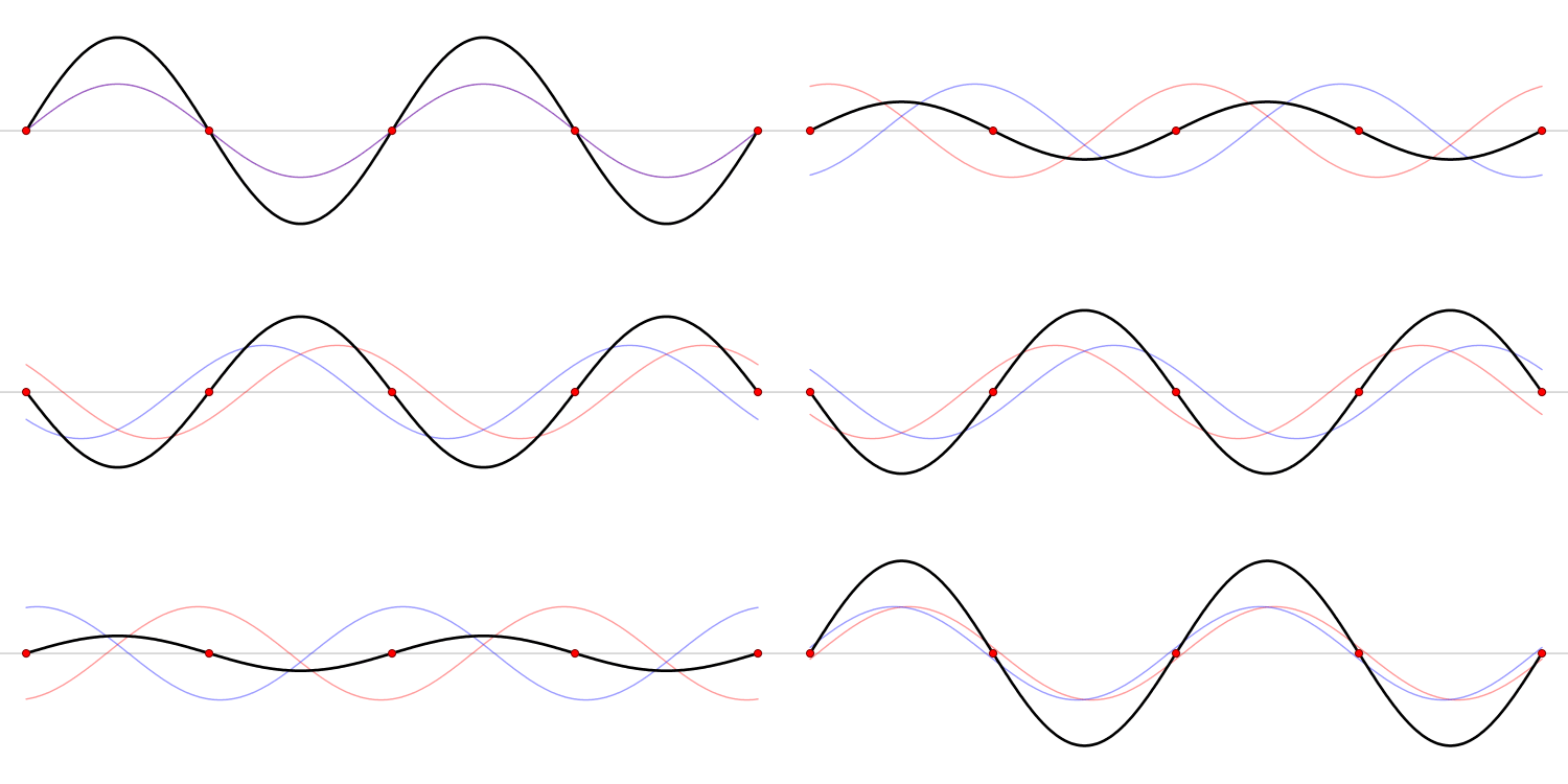
In the following animation you can see a standing wave where on the x-axis is represented time and at the y-axis potential:

In the red point at the center would be one wavelength λ , Now we have to be aware that the time axis is not linear related to the wirelength or nr of turns in an inductor, we know the current- magnetic field  increases exponentially. In the parametric oscillator we are now looking for a coupling by the E field  from one coil to the other, so for our example  if we place one terminal of the second coil ar 3/4λ, at this point we have a maximum in potential, wich would by capacitive coupling be reflected to one side of the  second coil, while the other terminal would remain at a potential node. This is why the potencial becomes very high in this coil combination.

Now this a s a simplified model as there is also the reversal effect from the second to the first coil, and the interaction of standing waves between both, which someone with better math knowledge might be able to explain more detailed.

If I am mistaken please correct me, thank's .

VIDURA.

Vidura posted this 20 October 2019

Hey CD I1(pico) means peak current 1, and L(p) the primary inductance. The circuit involves the current amplification like the mr preva setup. @zanzal The parametric oscillator principles relays on magnetic resonance, and a magnetic field does not change linearly in time, that is why the difference with the spacial distance or nr of turns. For example the ZPM is quarter wave relationship not half wave, because for inductance we have to use SQR 0.25 which gives a 0.5 relationship between the two windings Vidura.

Zanzal posted this 20 October 2019

@zanzal The parametric oscillator principles relays on magnetic resonance, and a magnetic field does not change linearly in time, that is why the difference with the spacial distance or nr of turns. For example the ZPM is quarter wave relationship not half wave, because for inductance we have to use SQR 0.25 which gives a 0.5 relationship between the two windings Vidura.

Good point, I forget that sometimes, but it does mean that your theory should be testable, since turns ratios other than 1:0.5 and 1:0.86 should be significantly less efficient. And winding it with a ratio of 1:0.71 should result in no AU according to your theory correct?

Jagau posted this 21 October 2019

Hy yoeimicro


I just got back from the trip and I just read the answer to my question.
Thanks for the answer, I understand better, but that begs another question.

Since you have idealized the inductance factor to 1,
what will be the number of turns for N2 if we have a ferrite core with a real factor of

7800 nanohenries and for n1 is 100 turns ?

Jagau

YoElMiCrO posted this 21 October 2019

Hello everyone.

@Jagau.
The above formula only applies if both inductors
share the same core, this will indicate that the factor Al
It will be the same in both cases.
No matter what value Al possesses, provided it is the same,
if on the contrary the inductors are wound on materials
with different values of Al, you must calculate the turns by
separated to fulfill the stationary relationship in the function of
longitudinal wave

@Zanzal.
The above hypothesis is the basis of the observed phenomena.
At least for me, I think I didn't understand your question.
In the shortest possible time I will explain what I think happens in the
Experiments performed by Vidura and me.

The truth is that I don't like to talk about something that still has many gaps
theoretical, it is only work and experiments that will gradually lead us to
partial or total understanding of these phenomena.

Thanks in advance.

YoElMiCrO.

YoElMiCrO posted this 02 November 2019

Hello everyone.

Due to work problems I have not been able to design
other experiments to fully validate my
hypothesis about the phenomenon that occurs between E / B.
Whenever I return from travel I have accumulated work
but little by little I have been finishing it.
I apologize.

Thanks in advance.
YoElMiCrO.

Vidura posted this 03 November 2019

Hey Zanzal
Good that you are trying to do experiments. It is not likely that the core size or material will be crucial for the effect.To set up a standing wave it is necessary to have two waves in oposite direction, and at magnetic resonance the amplitude will rise, I found the easiest way to use a unconnected scope probe beside the core as antenna fot tuning. For a slowly traveling wave there has to be a small difference in the frequency additionally.

For the first case any transformer setup will show the effect if the secondary is LOADED. There has to be current in the coils to produce a magnetic wave. POC  also will setup the standing wave ,if current is drawn.

For the other case of a travelling wave there has to be two different frequencys on both coils, where the speed of the travelling wave is relative to the difference between them.

I hope this helps.

Vidura


Vidura posted this 10 December 2019

Hello All!

a continuation of the investigation which was presented in the thread : "towards a more complete understanding of EM" , more tests about the unusual effects which have been observed in the "negative inductor circuit". I decided to continue  posting  in this thread, as the research was made in teamwork with YoElMiCrO, and you will see soon that there is also a relationship with the present topic of parametric oscillations. Here the Videos, there is more to come , I still have to do some editing.


Vidura

Vidura posted this 10 December 2019

When I decreased the frequency further, something unexpected appeared on the scope:

The sawtooth wave is changing in a sinusoidal shape, at this point would be a quarter wavelength .

In the next image we can see the form of a dampened sinewave of the current:

The pulse duration at the lowest frequency was around 20 - 30 us, the current drawing at 35mA@ 15V, and the 0.1 ohm shunt was getting slightly warm. I repeated the test with the iron core, a little bit longer pulses where required, and the frequency was slightly different, but the same effect and shape of the trace. 

I have observed some effects which occurred only on the measurement with the CT, it reacted very sensibly to the duty cycle, and eventually with short pulses the polarity reversed, the trace disappeared on the low side of the screen, and when the pulses became longer it changed to the positive side, in this direction following by the trace corresponding to the shunt resistor. Maybe I can make some video capture of this details later.

Vidura


Fighter posted this 27 September 2019

Very interesting indeed. I wasn't aware that formula is a derivation of N=SQR(L/Al).

This actually brings a more clear image about the functionality of ZPM.

I have the inductance of the coils, I need to find out the Al of AMCC-200.

Thanks Vidura &  YoElMiCrO !

Fighter posted this 27 September 2019

Zanzal, I think the experiment about testing the hypothesis of magnetic waves deserves its own thread (this one actually) so you can share details about it here, I would be very interested in reading the details and as you can see other members are interested too.

So when you have some time please update this thread with details as the experiment progress.

Thanks

Chris posted this 29 September 2019

Vidura, Awesome, excellent work!

I wonder if my video showing the earthing was of any help:


Excellent work my friend!

   Chris

Wistiti posted this 03 October 2019

Hi guy's! Awesome works!!! Really happy to follow yours works. I have a question about the formula, when you says turns, do you means inductance (Henry's) or real turns on the core?

It can be really different depending the ways you wind it...

Thank you !

Chris posted this 07 October 2019

@Vidura,

I would like to hear your opinion about my post:

My Friends,

YoElMiCrO and Vidura's work, to understand Fighter's work, is very important!

Lets take the following Experiment:

A Single loop of wire, the length of a single loop is: 111mm and we have 100 loops the same length.

Our 100 loops at 111mm each is equal to N1.

Our equation:

N2 = SQR (n) N1

Ref: YoElMiCrO


So, calculating: N2 = sqrt(0.25) * 100 = 50 loops at 111mm each.

Now comparing:

  • N1 = 111 x 100 = 11,100mm.
  • N2 = 111 x 50 = 5,550mm.


For Half Wave: N2 = sqrt(0.5) * 100 = 70.71 loops at 111mm each.

  • N2 = 111 x 70.71 = 7,848.81mm.


For Three Quarter Wave: N2 = sqrt(0.75) * 100 = 86.6 loops at 111mm each.

  • N2 = 111 x 86.6 = 9,612.6mm.


Now, if we look at the length of the wire:

  • 11,100 / 2 = 5,550mm = 1/4 wave, which is what we calculated for N2.


Respectively, we can get: 

  • 11,100 / 1.414 = 7,848 = 1/2 wave.
  • 11,100 / 1.154 = 9,612 = 3/4 wave.


The Frequency ( f ) = 27.00 MHz

The Speed of Light ( c ) = 299,792,458 meters per second

We know, for an Antenna, a Half Wave is the optimum Wavelength to transfer Electromagnetic Energy, this is: λ / 2

Where

  • Lambda ( λ ) = the Wavelength at Resonance.


Which means:

  • Lambda ( λ ) = Speed of Light ( c ) / Frequency ( f ).
  • Lambda ( λ ) = 299,792,458 / 27,000,000 = 11,103mm
  • 11,103mm ≅ N1
  • 11,103mm / 2 = 5,551mm
  • 5,551mm ≅ N2 calculated above ( N2 = 111 x 50 = 5,550mm


Remember this:


This, in combination with our Antenna Theory threads, here and here, with the thread here and here, means we have a lot of very special logic to study!


The Coils become Resonant at the Half Wavelength, which is calculated by the Quarter Wavelength of 0.25. This is using the Inductance, but means the Wire length of N2 is half that of the N1 as seen in the above Experiment, which is Lambda ( λ ) / 2.

However, please remember, this is only one way, many ways exist to get to the same goal! We are specifically referring to Fighters work in this thread.

   Chris


Please remember, many of the successful inventors before us gave us Radio Wave Engineering basics to follow:

Resonance frequencies may be maintained quite constant at high power levels so long as the load remains constant. We are all familiar with AM and FM propagation, where in the case as AM, the voltage amplitude varies, and with FM, the frequency is modulated.

However, the output power sees a constant load impedance, that of the matched antenna system. If this changes, the input to the antenna is mismatched, and standing waves are generated resulting in a loss of power. The frequency is a forced response and remains constant. Power is lost and efficiency becomes less and less, depending on the degree of mismatch.

Ref: Floyd Sparky Sweet - Magnetic Resonance.


I believe it is very important, very relevant!

   Chris

Chris posted this 07 October 2019

Hey Vidura,

I agree, I would like to hear Jagau's opinion and others also!

   Chris

We're Light Years Ahead!
Members Online:
What is a Scalar:

In physics, scalars are physical quantities that are unaffected by changes to a vector space basis. Scalars are often accompanied by units of measurement, as in "10 cm". Examples of scalar quantities are mass, distance, charge, volume, time, speed, and the magnitude of physical vectors in general.

You need to forget the Non-Sense that some spout with out knowing the actual Definition of the word Scalar! Some people talk absolute Bull Sh*t!

The pressure P in the formula P = pgh, pgh is a scalar that tells you the amount of this squashing force per unit area in a fluid.

A Scalar, having both direction and magnitude, can be anything! The Magnetic Field, a Charge moving, yet some Numb Nuts think it means Magic Science!

Message from God:

Hello my children. This is Yahweh, the one true Lord. You have found creation's secret. Now share it peacefully with the world.

Ref: Message from God written inside the Human Genome

God be in my head, and in my thinking.

God be in my eyes, and in my looking.

God be in my mouth, and in my speaking.

Oh, God be in my heart, and in my understanding.

Your Support:

More than anything else, your contributions to this forum are most important! We are trying to actively get all visitors involved, but we do only have a few main contributors, which are very much appreciated! If you would like to see more pages with more detailed experiments and answers, perhaps a contribution of another type maybe possible:

PayPal De-Platformed me!

They REFUSE to tell me why!

We now use Wise!

Donate
Use E-Mail: Chris at aboveunity.com

The content I am sharing is not only unique, but is changing the world as we know it! Please Support Us!

Thank You So Much!

Weeks High Earners:
The great Nikola Tesla:

Ere many generations pass, our machinery will be driven by a power obtainable at any point of the universe. This idea is not novel. Men have been led to it long ago by instinct or reason. It has been expressed in many ways, and in many places, in the history of old and new. We find it in the delightful myth of Antheus, who drives power from the earth; we find it among the subtle speculations of one of your splendid mathematicians, and in many hints and statements of thinkers of the present time. Throughout space there is energy. Is this energy static or kinetic? If static, our hopes are in vain; if kinetic - and this we know it is for certain - then it is a mere question of time when men will succeed in attaching their machinery to the very wheelwork of nature.

Experiments With Alternate Currents Of High Potential And High Frequency (February 1892).

Close