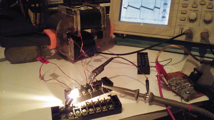
Chris's Non-Inductive Coil Experiment

  • Topic Is Sticky
  • 29K Views
  • Last Post 04 July 2023
Chris posted this 08 October 2019

My Friends,

I am going to show a small experiment, one that follows the works of Andrey Melnichenko and even Tariel Kapanadze's works and as we know many others.
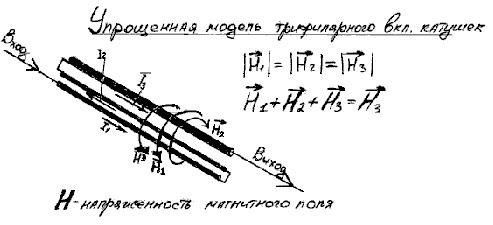


We have discussed here before, the fact that H3 is H3 simply because H1 and H2 cancel out: H1 + H2 + H3 = H3, why is this so, because H1 is Positive and H2 is Negative! We have seen this equation before: 1 + -1 + 1 = 1.

I think with Fighter's success recently, its time for some hands on!

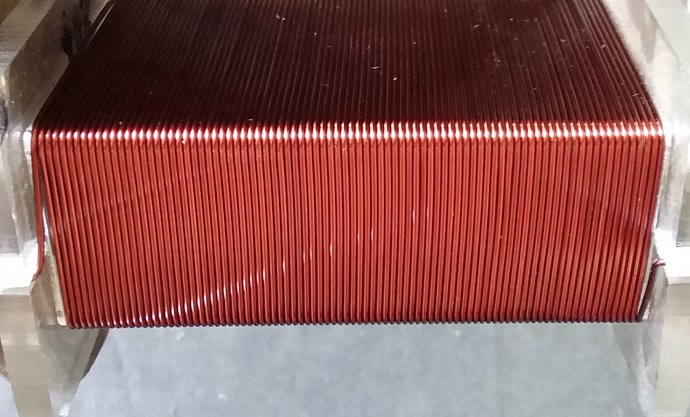
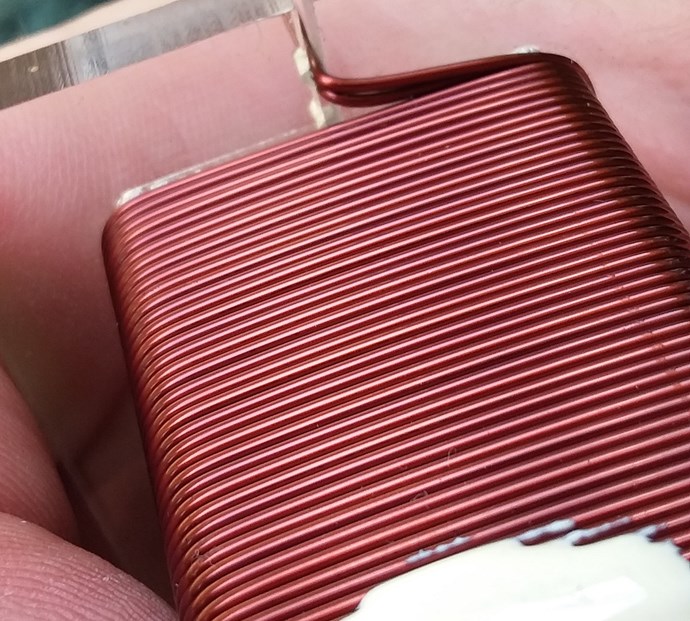
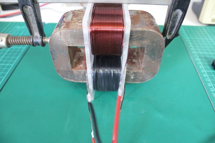
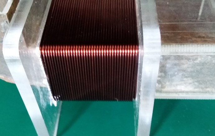
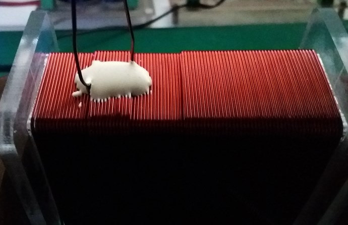
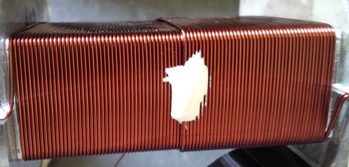
  • First Layer: 88 Turns.
  • Second Layer: 43 Turns.


Layer One:


Layer Two:
 

Turns Direction:
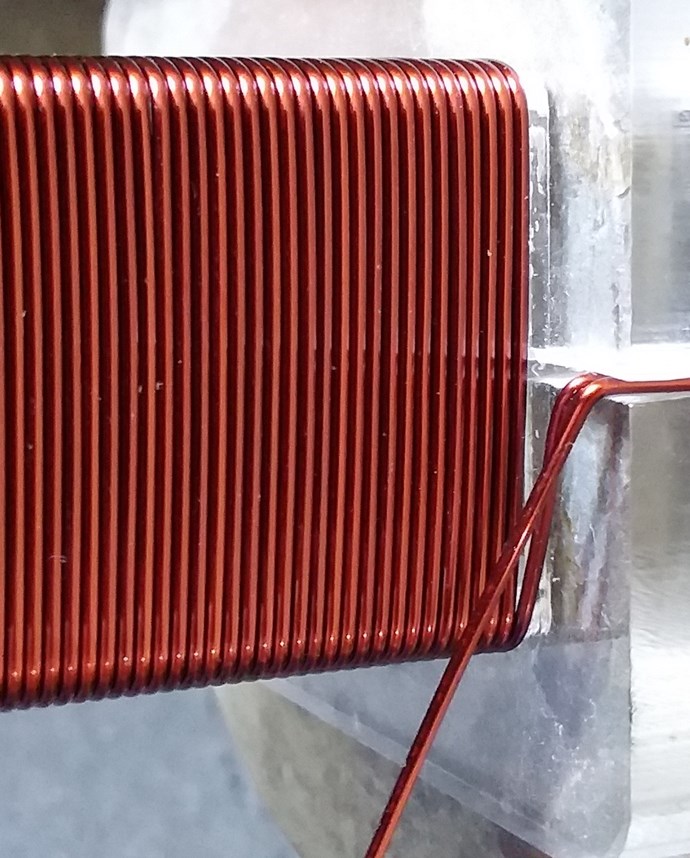
 

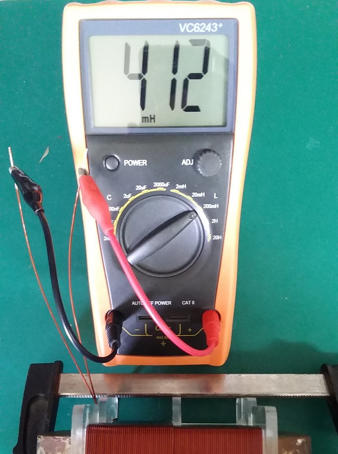
Layer One Inductance:
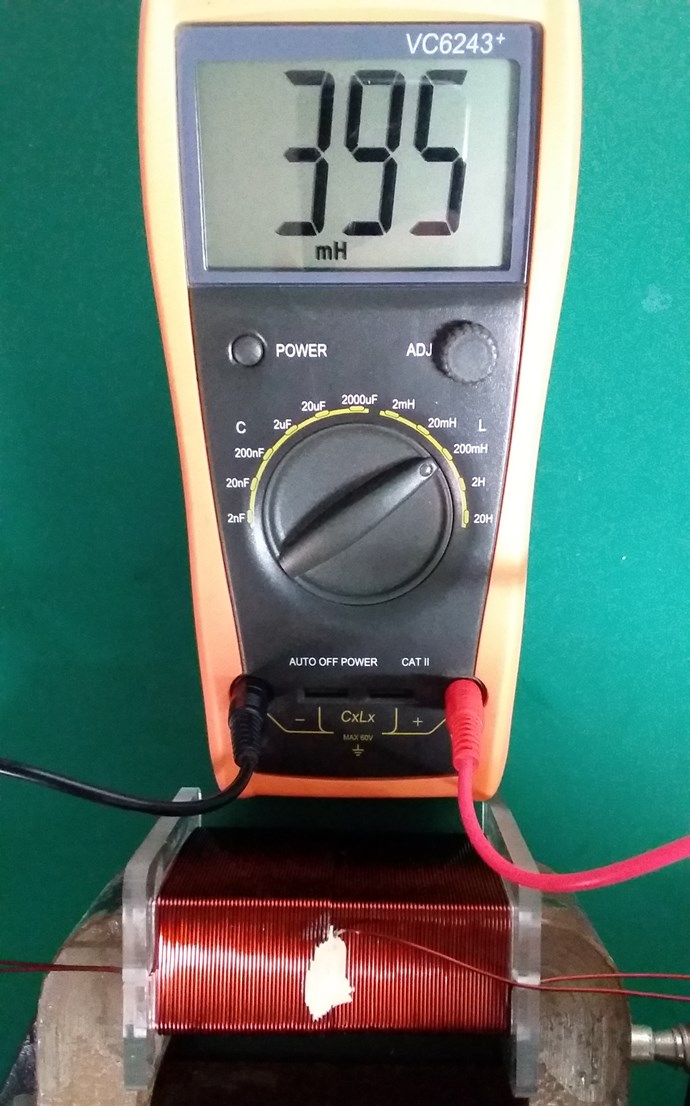
 

Layer Two Inductance:
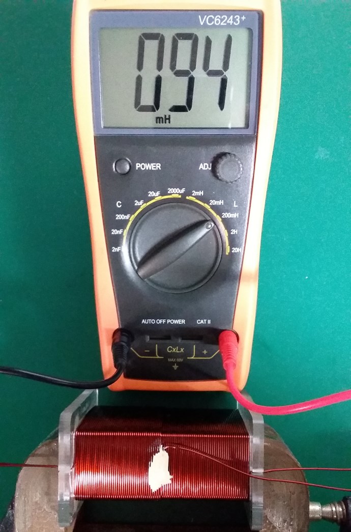
 

Non-Inductive Connected:
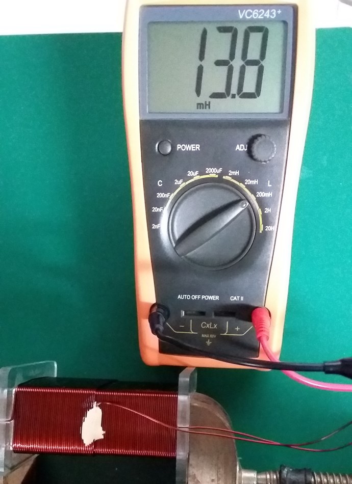
 

Layer One Resistance:
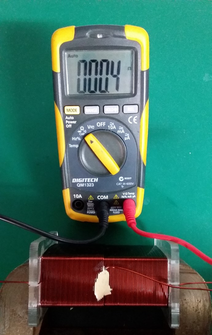
 

Layer Two Resistance:
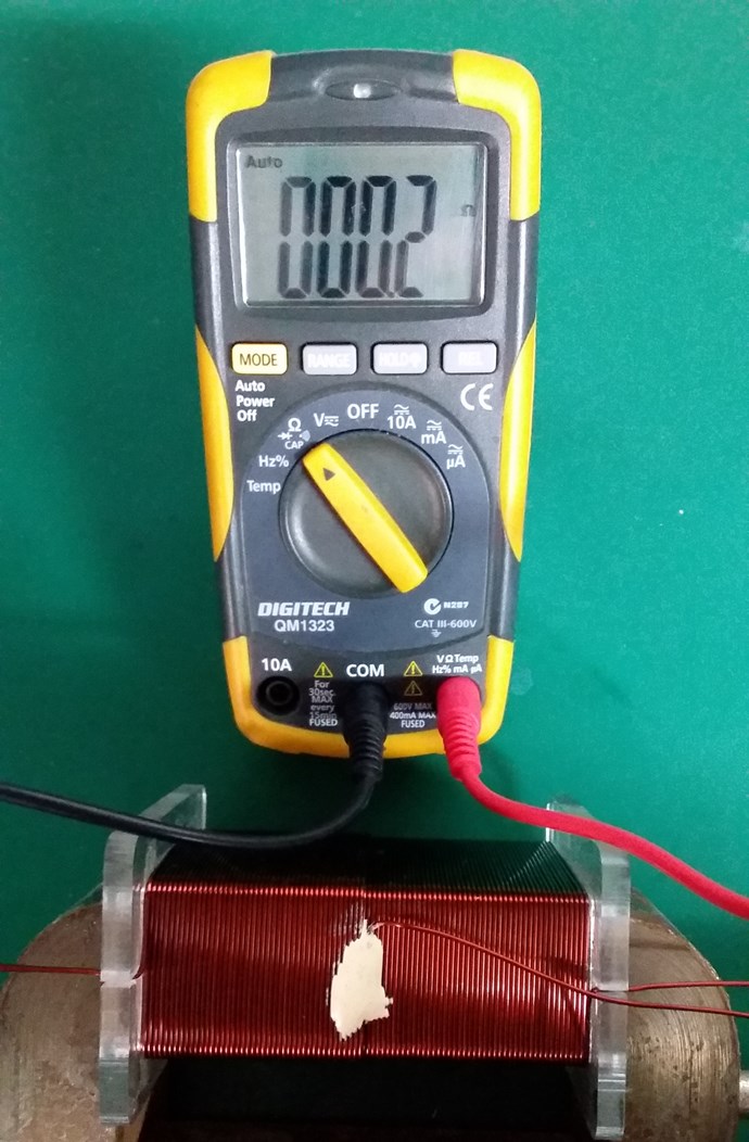
 

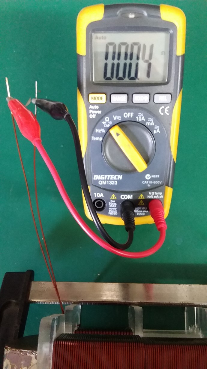
Closed Loop Resistance:
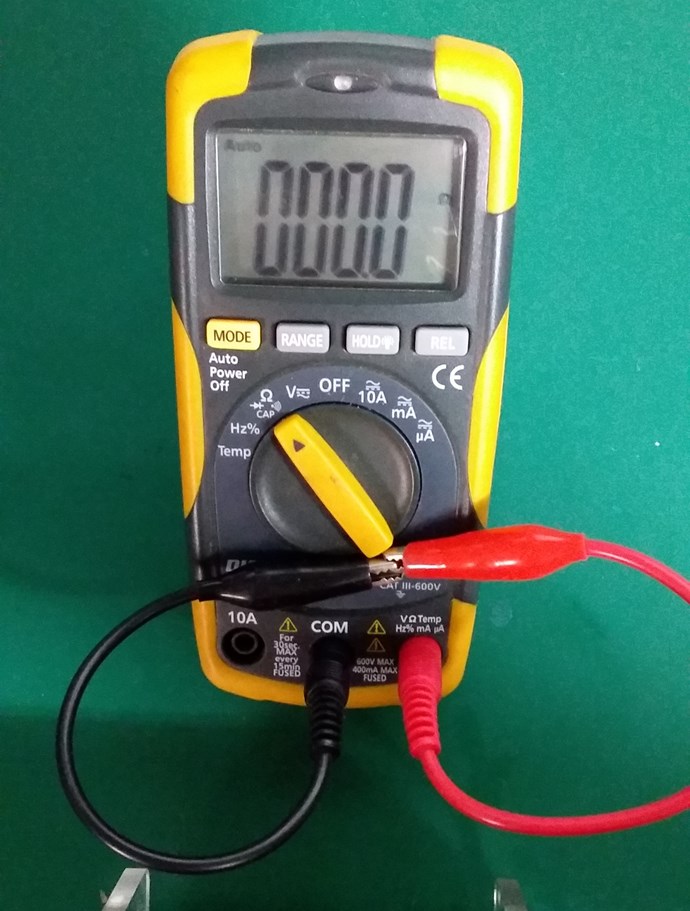
 

My Coil, like Andrey Melnichenko's, is 0.33 + -0.33 + 0.33 = 0.33.

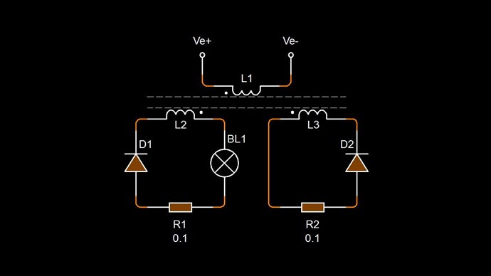
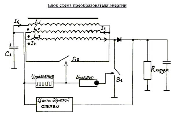
Two thirds of my Coil is canceled out. My Circuit looking like this:
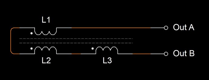
Where:

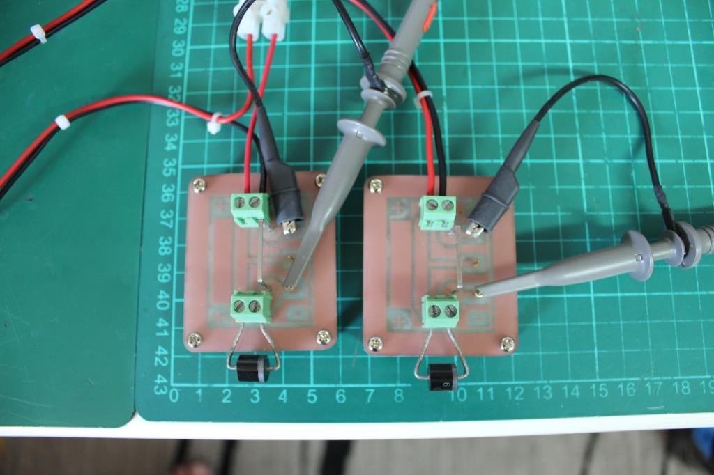
  • L1 and L2 are Non Inductive.
  • L3 is Inductive.


If this Coil is carrying 1 Ampere of Current, and exactly one half of the Coil is Non-Inductive, then Turn for Turn, only 45 Turns will create an M.M.F, which is considered as 45 Turns x 1 Ampere = 45 Ampere Turns or 45At.

Science tells us, that Turn for Turn, where we have Non-Inductive part of the Coil, this part of the Coil does nothing! Creates no Magnetic Field, therefore does nothing.

However, from Experiment, we know that this part of the Coil DOES do something! Remember Floyd Sweets paper: Nothing is Something, this is the same!

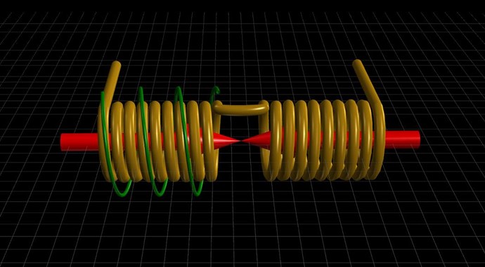
At Resonance, we have a perfect Standing Wave! We know this as Magnetic Resonance! Where each Magnetic Field is 180 Degrees out of phase:
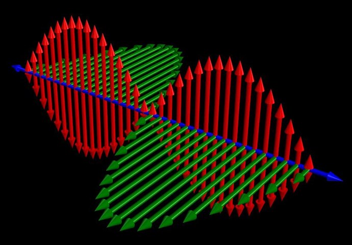
 

Now, straight away, we should see a problem! Why? Kirchhoff's Current Law says the Current must be equal at every node, but we have Turn for Turn, one Coil that is Inductively Zero, and another Coil that has only a part of the Induction canceled!

In the specific case of positive charges moving to the right and negative charges to the left, the effect of both actions is positive charge moving to the right. Current to the right is:

I = da+ / dt + da- / dt

Negative electrons flowing to the left contribute to the current flowing to the right.


Each node does not equal the other, so the Circuit must balance out, Current is Increased as the Standing wave shows us.

Remember what Induction is? See here: Non-Linear Inductance

Induction gives us an approximation on the Coils ability to carry a Current: L = ε / di / dt

By Bringing a Coil arrangement like this into Resonance is our task.

Where each Electromagnetic Wave travels in opposite directions. One through the other in the same space.

THE NATURE OF SPACE

Space itself is the ability to accommodate energy. Consider for a moment the following illustration:

A signal (energy) is transmitted from point A to point B. A and B are separated by a finite distance. Consider three periods of time:

  • The signal is launched from A.
  • 2) The signal resides in the space between A and B.
  • 3) The signal arrives at B.

If (3) occurs simultaneously with (1) we say that the signal has traveled at infinite velocity. The signal has never resided in the intervening space and therefore there exists no space between A and B. A is virtually at the same point in space as B. For real space to exist between A and B it is necessary that a signal travelling between them be "lost" with reference to both points for a finite period of time.

Now we know that for real space to exist between two points a signal travelling between them will propagate at a finite velocity c, ( c = 1 / √με )

If a signal will not travel between two points, as in the case when c = 0, then we can also conclude that there is no link or intervening space between them. 

Ref: Floyd Sweet - Nothing is Something.


Floyd Sweet tried very hard to make c = 0! What does this mean? It is simply a Standing Wave, a Team Wave was used:

It is a simple matter using the equations E / H = √με and c = 1 / √με for a team wave to get rid of H and c and so convert the first equation into the well known equation for energy density in the so-called electrostatic field.

Ref: Floyd Sweet - Nothing is Something.


I have pointed out: Why 'C' is equal to One in these Devices.

We have a lot of data!

   Chris

Order By: Standard | Newest | Votes
Chris posted this 27 October 2019

Hey Jagau,

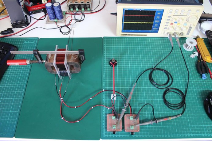
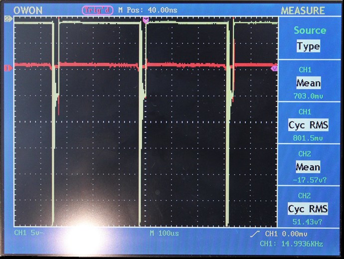
Just a single DC Pulse, 10% Duty Cycle of 3000 Cycles per Second.

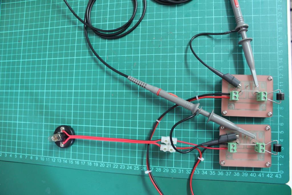
Its very easy to replicate, only getting the Diodes in the right polarity is the important thing. Worth using a Re-settable Fuse just in-case.


What I have shown is just the start!

It is the beginning of a new world of Machines!

Patience and some very serious thinking will be required to further what I have shared. I know we here have all done the reading, got the background, we already understand what I have shared, we all know the importance and what exactly to look for! So, I am here, any questions please post here or PM Me.

I would prefer to keep technical questions here on this thread so they can help everyone!

My Friends, we begin! A journey to the future!

   Chris
Chris posted this 08 October 2019
My Friends,

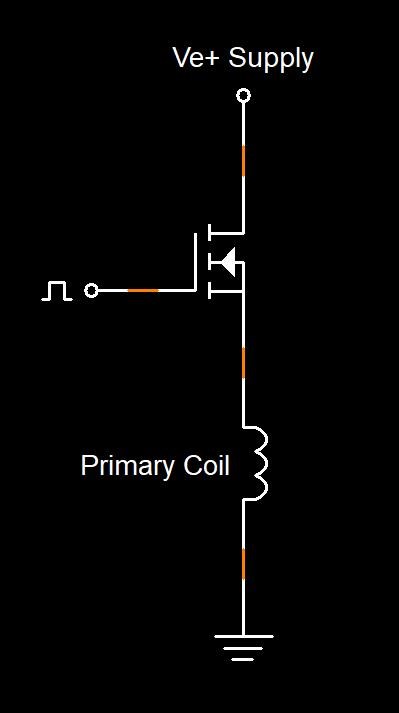
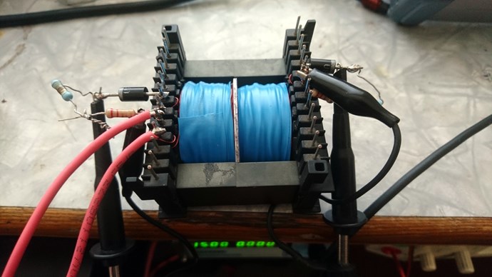
I am going to show Transformer Coupling, to drive my Experiment.

Input Coil Turns: 2 Layers 37 + 39 = 76 Turns.

The Input Coil:


Input Coil Inductance:


Input Coil Resistance:


You can see, I have less turns than the single Layer on my Output Coil, first layer, but the Inductance is higher:

  • 84 Turns compared to 76
  • Inductance of 395 compared to 412


Geometry, the Length of the Coil plays a role here.

The Resistance is almost the same: 0.4 compared to 0.4, no visible difference.

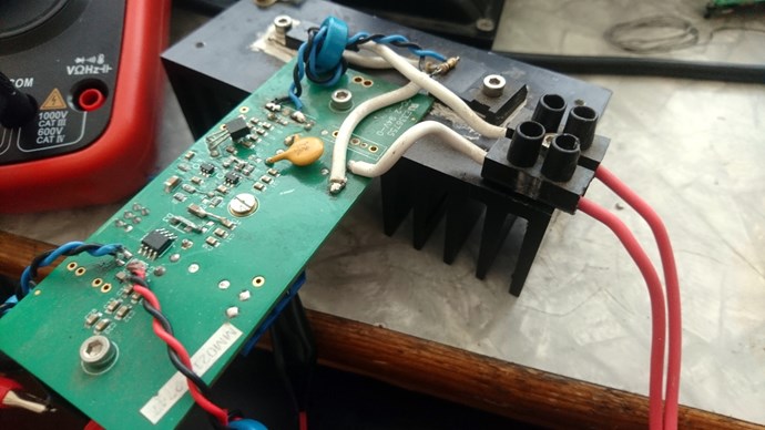
Next, I will show the drive on the Coil, from my Switching Unit.

   Chris
Chris posted this 09 November 2019

My Friends,

A small review:


Many experiments shared, Seven Videos in total on this thread, one with a successful result. I need you all to help me do this, I cant do it for everyone else. 

   Chris
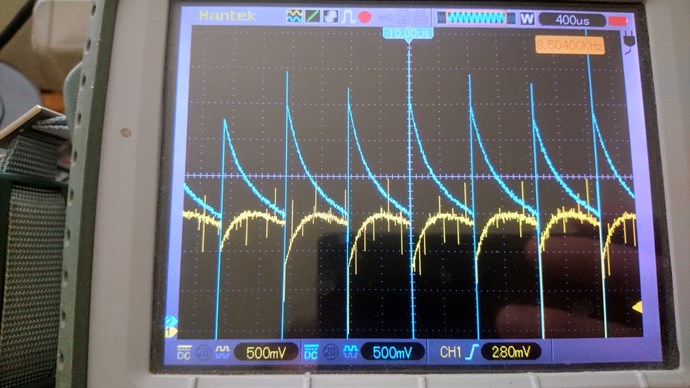
Chris posted this 15 November 2019
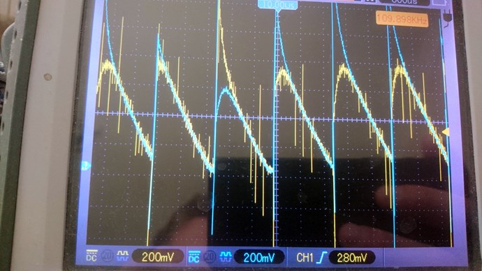
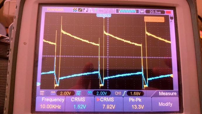
My Friends,

A new video with some info:


Hope this helps!

   Chris

Chris posted this 01 December 2019

My Friends,

On the 16th January 2020, I would have been sharing what I have learned for five years, publically. I have shared from 2005, my experiments on my website: hyiq.org, but as a figure, supporting what I have learned, sharing with others, and making myself available for questions and support, it will be five years.

We have had some successes! We have faced many battles, with Non-Believers, or Skeptics. Not that I want to battle with them at all, I just want them to stay on their side of the fence and let us be! Let us work and progress, as we so desperately need to!

After some lengthy planning, by changing the Game, we have managed to isolate Trolls from our progress!

We no longer suffer the Trolls, they have lost their war. Now out of a Job!

The other forums still suffer from Trolling, simply because they are not properly Moderated!

Aboveunity.com is unique, we are Light Years Ahead of the other forums! We have technology they have not yet even dreamed of!

They copy our work, simply because we have forced their hand! We have played a game of Catch Up or be Left Behind, and made a mockery of, as time progresses!

I have released this series of videos to commemorate this Five Year Anniversary, to show all Readers and Followers what I have been telling you is True and Correct!

Now, all of you, the ones that have Read, and Followed my work, are getting results!

After saying this, its not me making this work, its you! All of you, working to make this world a better place! Those of you working hard to understand something as simple as it is, to make progress and share their work, its you making a difference.

Please, all Readers, join us, make a Difference, Be part of something Better! Share your work here, you are SAFE HERE, I promise, just ask our other Members.

Dont forget, what I am showing you is exactly the same as an Electrical "Generator". There is no difference, except we have gone to an Asymmetrical configuration!

   Chris

Chris posted this 16 December 2019

My Friends,

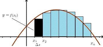
Energy is always considered the Total Area Under the Curve. An example of this Area Under the Curve is:


No matter how you do it, the more Area Under the Curve you can achieve, then the More power you have, and if your'e smart enough, you can do it for free! 


In a standard transformer, if the Secondary is loaded, then the Secondary carry's a Current that changes in time!

This Current Changing in Time, is equivalent to a Magnetic Field changing in Time!

I want to quote:

An alternate explanation for the current gain in the UDT is to consider each secondary winding as acting as the primary winding for the other secondary winding when an output current is drawn because the two secondary windings generate geometrically opposing fields.

Ref: A Free-Energy Device by Paul Raymond Jensen


Most of you are likely tired of me repeating myself! Please understand, I am also doing this for the new comers.

Much work to do, much to learn, much achieve...

   Chris

Chris posted this 06 February 2020

My Friends,

Mohamed asked me for specifics, I have covered in detail in the videos if you watch, which I recommend, but following is a list:


To start:

  1. Three Coils, One Input Coil, 22 Turns 1.6mm, Two Output Coils, 0.8mm I recommend around 180 Turns.
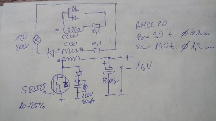
  2. I have provided Circuits, see below.
  3. Frequency 3,000 Hz @ 10% Duty Cycle.


Circuits:


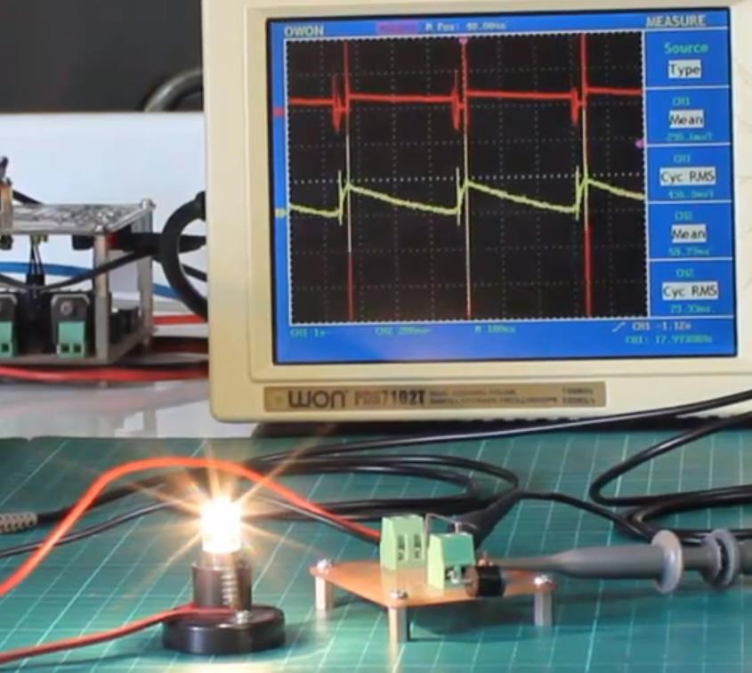
Putting a Diode on your Input, blocking Energy coming back to your Input is not a good idea! Try different Load's, the Load Resistance can make a difference! This is another reason this can be a bit fiddly. I used a 12V 300ma globe. This load is one of my better ones.

Make sure your Input Switching is clean and sharp.

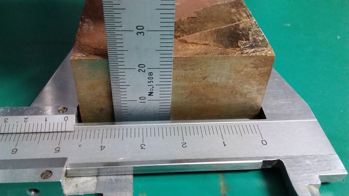
Use a Core that has a reasonable Cross Sectional Area, CSA, remember it's the Magnetic Field, the Volume of it and how fast it changes in time that is important here! My Core, in the video is:


Length x Width is Area of a Rectangle, so: 49 x 23 = 1,127‬ square mm's. Your Coils Impedance, and the less it is the better, but remember, you need Voltage, get it up! Don't go to high though, its far to dangerous other wise!

This is info that's already available on this and other threads.

I hope this helps some!

   Chris

Chris posted this 11 October 2019

My Friends,

Its taken a while, I have been pulled away a few times and also had a few other problems to deal with.

The following Video is Long, so beware. Its also a video aimed for beginners!


I hope these experiments prove to be useful to others!

   Chris

Chris posted this 24 October 2019

My Friends,

A learning video, making discoveries and working toward Magnetic Resonance:


I show many problems, and give some answers! We have a new video coming soon and the next one will be just a little better again!

We must do the small experiments to move forward!

   Chris

Chris posted this 28 October 2019

My Friends,

What we have learnt in this thread, and of course in preceding threads, here at aboveunity.com, give us the very basis of the future technologies to come! We are truly Light Years ahead of the other forums!

Other forums are actively coping our work!

The point of this post: Stick to Facts and hard data!

Soon, if not already in progress, we will see misleading information released by other prominent members of Other Forums! They will happily Mislead you if you let them! Don't let them!

We must turn a Symmetrical Transformer into an Asymmetrical Transformer!


Facts:

To make this work, all you need is:

  1. Three Coils, two can be used but this method is not my preferred method.
  2. Two Diodes.
  3. A Core that you have enough room to move the Coils around.


BS:

They may tell you that you need:

  • Magic Magnets.
  • Magic Diodes.
  • Magic Wire.
  • Magic Input.
  • Magic Core.
  • Magic touch...


Of course we all know what BS Stands for! Don't listen to them! Ignore everything except the facts I have laid out!

My Input is like so:


The Circuit in the Video:


Which is this:


This is the other Coil, some of the data is off screen:
 
 
This is Asymmetrical Regauging:


The Input was DC 12V @400ma. Above is the Output, some data off screen, my 10x probes are not enough to accurately grab all this data.

This is just a very simple, successful experiment! Andrey Melnichenko was right, but just had the implementation wrong in the pdf he shared. I have implemented: How to build your own Above Unity Machine using the knowledge I have gained in this Thread and others. This works as I have shared for many years!

Is science and the world going to move forward and learn from these simple experiments on this and other threads? I hope so!

I hope this helps! Its easy and Simple, no need for any complication!

   Chris

dewetw posted this 30 October 2019

Hi,


I love the work that you guys do, but I don't always have the time to experiment myself. However, this time I did and I got the effect that you are talking about - the saw tooth. I played around with it lots and got mere perfect saw tooth on both output coils. Other setting made output coil 1 way deliver more than output coil 2 and I can also go slightly to the other side. I even got to settings where one output coil ramps up during the off part of the applied pulse.

Now, I never saw any result where I am getting more than about 0.82 COP. How important is the core material? - I am using a high frequency ferrite transformer core, N87 material I think. Output coils are about 35m of 0.5mm enamel copper wire each. Input coil is about 12m of the same wire to give that 1 to 3 ratio that you mention. I have played around with gaps between the core halves and even removing them altogether, one side and the other and both. Those cores stick together when in contact and powered up.

My driver is based on the CREE Wolfspeed and supplies a negative going pulse very efficiently. I can easily switch into the megahetz range while only costing about 15mA at 15V to drive the mosfet - I use ZXGD3005 after the mosfet driver to drive the gate even harder/more quickly, works beautiful. Shortest pulse I can generate is about 30nS. I am using non-inductive resistors as loads. Diodes: UF5405

Is there something I am missing?

What direction should I head in next?

Core material?


Coil setup:


Driver circuit:


Output coil 1 giving more then coil 2 giving more:


Some saw-tooth under different settings:


Thanks

Chris posted this 05 February 2020

Hey Loz,

All of us have good and bad results. Its normal. Even now sometimes I have to work at it for a while before I get a machine working. Its hard to pin down the exact causes! Sometimes too many turns, sometimes not enough, sometimes tuning is hard, sometimes easy.

Sometimes getting the best result is a lot of fiddling. But, when the Machine is ideal, for example when the wave form is optimum, and one does not have too much dead time and so on, then normally this means your'e going to get good numbers.

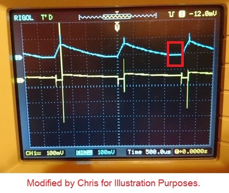
Above, the dead time, we saw some examples:

From here.


I pointed this out to Atti also:


You could increase your Frequency, as there is some dead time at the end of your scope shot, in the waveform:

The post Here.


Sometimes this is a sign you have too many turns on your Partnered Output Coils also. When we have good waveform, like this:


We get much better results!

As we know Wave Amplitude is an indication of Energy, V x I x Cos( Theta ), and so by increasing the Amplitude, is beneficial. The old: Current ( I ) = Voltage ( V ) / Resistance ( R ). Increasing V increases I.

All of us can help, no matter what! Let us know how your'e going and we can share our experiences. You have had a taste and know what its about, so if you follow the same rules as before, you wont have any trouble.

Best Wishes, have an excellent holiday!

   Chris

Chris posted this 11 February 2020

My Friends,

This post is a specific post about the broadness of the technology I am sharing with you.

In the old days when Akula was sharing information, his comments on Bucking Coils and Standing Waves and so on were hard to decipher but were there if one took the time to observe!

What I am sharing is broad!

Fighter has shown how broad this technology is!

Don't limit yourselves to one narrow path! The concepts are all the same, yes the same! The same ideas, same concepts. I will explain:

Akula tuned the Frequency and Duty Cycle to maximise the Magnetic Resonance, increase the Potential in the Coils and as we learnt in The Mr Preva Experiment, the Currents are Equal and Opposite. The Input to Output ratio is achieved by Tuning the Frequency and Duty Cycle, this video shows a similar device, but uses the same concepts:


The same basic idea, Coils, as the Mr Preva Experiment:


The Asymmetrical Regauging process is the same. Its all the same processes! Same concepts! A short pulse, Duty Cycle at a particular Frequency, when the Coils are Magnetically Resonant is where we gain Energy, Excessive Electromagnetic Induction occurs, well beyond the Unity Boundary!


Timing is a difficult task in these circuits, but others have achieved success, its not beyond reach, but be prepared for a difficult task. Working with the Coils, Partnered Output Coils, learning them first and then moving forward after learning how they work is the best path forward.

My Advice: Get the Coils working, then build the Circuitry around the Coils! Stick to the basic concept here, Electromagnetic Induction, to amplify both Voltage and also Current, don't let any complication creep in!

Best wishes,

   Chris

Ourbobby posted this 08 April 2020

Hi Guys,

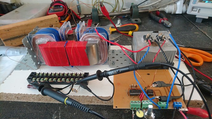
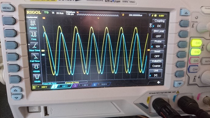
                Have eventually got my Meg replication built!!. Winding the secondarys' took a bit of time getting them wound smoothly with the fine wire. Anyway, these are my first photos and first connection! Have not looked to see if my coils might need swapping yet. The Yellow trace is a 100:1 probe the Blue trace is 10x probe. The yellow trace is on the CCW coil. At least i think it is CCW, always get a bit confused with the winding direction. Showing just over 1kv.

Incidentally, i have put a thin plastic separator between the C sections.

So this works!  I shall look at it for a short while to see what it tells me. Reassuring that I can build something that works!.

Regards

ourbobby


Atti posted this 17 April 2020

Some thoughts ....  

Chris posted this 07 May 2020

Hey Ourbobby,

YoElMiCrO is right!

This video may help some:


The Noise, the Knocking, the Vibration, its an indicator. I also show here, a similar thing:


Remember Floyd Sweets Sponge:


When the Core starts getting noisy, you have a very large Magnetic Field Opposition, you know your'e getting close! Coil Polarity can play a role!

Best wishes,

   Chris

Jagau posted this 09 October 2019

Excellent Chris

I think the junction between L2 and L3 will give you double the input power?


Jagau

Chris posted this 09 October 2019

Hey Jagau,

When you say:

I think the junction between L2 and L3 will give you double the input power?


I think the Current will double, but double from what to what, I will show more soon.

Best wishes

   Chris

Chris posted this 09 October 2019

Sorry I thought it was a replication of melnichenko when he said this


Since the current in the coils of the same, we believe the resulting voltage in the time T2 is twice to the accumulation of energy
expended at the time t1.


Jagau


Hey Jagau,

Yes, you are correct in this situation! As we have 2x the turns on the First Layer and the Capacitor is directly connected through the Diode, then 2X the Voltage will be present at the terminals.


This is of course only true when the Coil: L2 is shorted in the above diagram. When L2 is un-shorted, then the Circuit will only have the Voltage of a Single Coil.

I have a little more to add soon.

   Chris

Chris posted this 13 October 2019

My Friends,

As I said in the last video, I needed to drop my turns down on my Input Coil. This is an Image:


So now I have an input Coil of: 12 Turns.

This is a difference of: 76 - 12 = 64 Turns. Also because, as was also stated, we have whats called Unity Coupling now, we should get much better Coupling from Input to Output.

Remembering, we do only have an effective 45 turn to 12 turn Coupling. So that's a step up of: 3.75

A video is currently being processed.

   Chris

Chris posted this 17 October 2019

My Friends,

The video: "Non-Inductive Coil Experiment - Video Four" gives us a specialized effect related to a years long problem!


Please, for all members, what might be the techniques we could use to over come the worst of the problem we are seeing? To remove the effect from our system, so we can by-pass The Second Law of Thermodynamics, Energy can not be Created nor Destroyed?

Of course, technically, we never create or Destroy, we Pump from the Source!

I don't expect the establishment to ever understand that, not this decade anyway!

   Chris

Chris posted this 25 October 2019

My Friends,

Solutions to problems come from our intellect. What is our intellect?

the faculty of reasoning and understanding objectively, especially with regard to abstract matters.

Ref: Oxford Dictionary - Lexico


Our experience gives us the ability to use our Intellect to solve the problems we face! Today's video is about solving the very simple problems we have seen in previous videos!


With an average view time of: 8.46 minutes, I think my videos are too long?


We believe in the systematic understanding of the physical world through observation and experimentation, through argument and debate, but, most of all, freedom of will.

Ref: Stargate - The Ark of Truth - Alteran woman


I enjoy wise quotes...

Coming in video Seven, Asymmetrical Regauging:


On another note: over at one of the other forums we are seeing them copy our work to a tee, exactly, almost word for word. You can see here: I wish them luck, even though they are not giving anyone credit for the work they copy!

   Chris

Chris posted this 27 October 2019

@Fighter, 

My Friend, your'e right, there is a "Higher Purpose"!


@All Readers,

Asymmetrical Regauging is a CRITICAL aspect to Energy Generation, We always have a Regauge Period, then a Work Period. This is Critical, and also, this needs to be Asymmetrical!


I am thinking this video might be too early to share, perhaps we might not yet understand it. I feel previous Videos may not yet be understood properly?

In the following Video I show Asymmetrical Regauging: 10% On Time and 90% Off Time


This is it gals and guys, this is the Lollie!

IMPORTANT: Now, please understand, one can have Asymmetrical Regauging and still be Below-Unity! Some Fiddling is required! The Coils Slapping together Creates a Voltage, then the Current can be calculated: I = V / R

   Chris

Chris posted this 28 October 2019

My Friends,

An Asymmetrical System is critical to making this work!

I think we need to start thinking about the Magnetic Field, particularly the Magnetic A Vector Potential, or here, and how far past, what we think of as a Boundary, the Magnetic Field can really extend!

I posted HERE some information about this many yeas ago:


Does a Magnetic Field extend past the Repulsive Force of another? Where is it that interaction of Fields are Really Occurring?


What we see today, in Experiment, shows that more than one Magnetic Field can Propagate through a Core at any one time!

This is so very important!

   Chris

Jagau posted this 09 November 2019

Another good video my friend

I can feel your concern and it is legitimate.
We are fortunate to have here a clean website with polite exchanges

and since I have been on this forum, I have made a lot of progress.

Thank you Chris for everything you bring us.

Jagau

Vidura posted this 09 November 2019

Hey Chris, Sometimes I feel like you that there should be more responsive actions. But the universe has it's own timing, every now and then the things stuck and all seems to be difficult and all the efforts we put seems to be in vane. But then in the next moment everything changes, and without doing anything all begins to flow again . I know the effort you put to keep the forum running and sharing your experience. By the way i had a very busy time as well , so it was not possible to continue contributing . When ever I can i do it with all my love and dedication. So be patient my Friend, certainly all the efforts will bring their fruits on time, and it will help to make the world a better place. Vidura

Chris posted this 13 November 2019

My Friends,

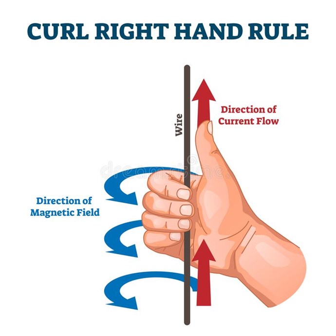
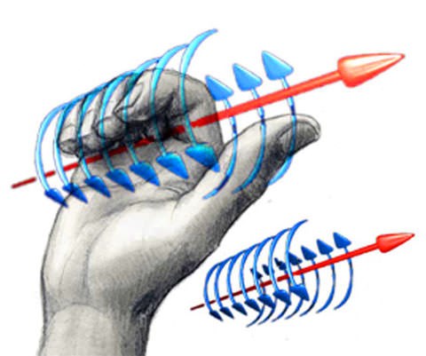
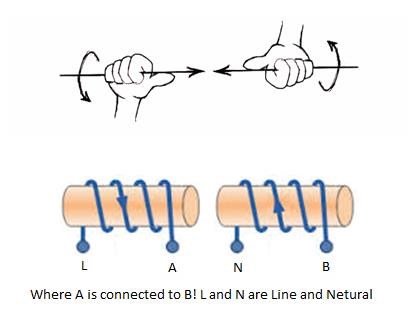
Remember, Don Smith, Floyd Sweet, many before us, the lessons they taught us: Use the Right Hand Grip Rule to see what Don is Saying!!!


Dont let this slip by, you may never get the chance again!

   Chris

Jagau posted this 15 November 2019

Second trial   


The frequency is lower about 2.7khz and I am getting closer.  

Jagau

Chris posted this 18 January 2020

My Friends,

Someone is preaching to me! The latest message:


Some people are so narrow minded!


Why is some person I do not even know preaching nonsense? Oxygen is one of the worlds most deadly Gasses, however we need it to breath! Without Oxygen a Match Stick could not light! What is wrong with people?

   Chris

Jagau posted this 18 January 2020

Hi Chris

They write this because they know we are close, so it tires a lot of people.

Jagau

Chris posted this 25 January 2020

My Friends,

Many times I have posted on how Partnered output Coils work. Today I tried to post to the 8Kun boards. Many do not believe. Feeling the water, its easy to see that many distrust something so simple.

We, those of us that have done the work know better. I have said it before, smart people are often the dumbest! There is a deeper meaning to this statement.

It appears the promises that our old mate TinmanPower now known as OzSolarPower, have flopped as usual. A bit sad, this is what Tinman has come to, never ending broken promises! These tactics are why others do not believe those of us telling the truth!

Perhaps today we should look at the laws of Electromagnetic induction again. The series I have shared with you:


In the video's above, I have laid out a lot of information! Video Seven shows a functioning Above-Unity machine. What we have learnt in the videos, shows how the manipulation of Magnetic Fields can induce a Solid State Generator, the only thing moving is the Magnetic Fields in time!  

Many others here have replicated these effects and some have gained the results we have shown.


What have we done?

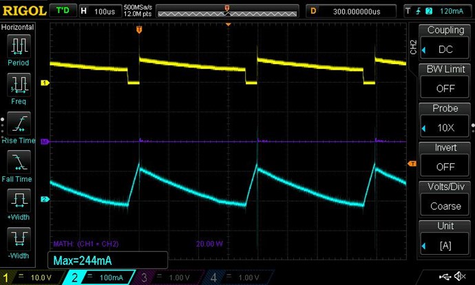
There is two processes occurring in Time:

  1. Accelerate Charge down the Wires - Green part of the Triangle.
  2. Decelerate the Charges in the Wire - Red part of the Triangle.


The Green part of the Triangle shows what I call: Reduced Impedance Effect

This is a very important part in the process! The Reduced Impedance Effect allows for the Coils to get to maximum amplitude very fast! You may remember the experiment I did, showing how much faster the Currents and there fore the Magnetic Fields can grow to maximum amplitude:


FROM:


TO:


From 75 milliseconds approx, to 500 microseconds, a factor of: 0.075 / 0.0005 = ‭150‬ times faster. This is the same reason we see the Triangle get to maximum Amplitude fast, but when our Input turns off, the Output Coils change their Impedance / Reactance, and they don't allow the Current to decay immediately. The Current is forced to decay linearly over time. We have referenced this before:


Again we show the Triangle:


Remember, this is Asymmetrical Regauging:


How the Oscilloscope measures the Waveform:


Remember, we have two things we must take into account:

  1. Amplitude ( Y Axis ) = Value of the Potential Measured.
  2. Time ( X Axis ) = the time the Amplitude is non Zero during the measured time frame.


So if we have more area under the curve on the Scope when our Input is off, compared to when our Input is On, then the area shows more Power, Voltage x Current x Cos( θ ), is being measured.

Our machine has become a Charge Pump, a system that requires Regauging every X seconds, the Frequency and Duty Cycle of Operation. We have invoked the use of Magnetic Fields to pump Current in the Wires exactly the same as our old reference video, the Hydraulic Ram Pump: Energy Machine Operation


We have offset the Forces of Magnetism ( M.M.F ) so our Input is not negatively effected as much as we would normally see in a normal Transformer.

   Chris

thaelin posted this 04 February 2020

@Chris:

    No matter Chris, stand by your convictions. Never relax your rules here and this will always be the place to share and prosper.

I have since left most of the other places available due to the fighting and mis-info things going on. I still have a version of linux that was made strictly for research purposes and it had a strong set of rules to belong to it. They were always open to other ideas and versions but would not tolerate any indiscretions towards any other member. It worked well and that is how a research place should be run. Voice your opinions and then discuss it with your peers. Keep it sane and proper and you will always be in good standings with the rest.

Bravo


I have since started working on a type of motor-generator system with added goodies and as it starts to come together, I will start posting progress here. Not sure if non-members will be able to see it, but will hope they can and share it on the other places that I will not go back to.


thay


Captainloz posted this 05 February 2020

Hi Chris and all,

I wish I had more results I could share.  I know I haven't been contributing.  It is so hard to stay focused on one thing! I tried many different experiments with the ferrite toroid cores I had set up, but none of them worked out as well. So I bit the bullet and invested in a Metglas core from Mouser.  It arrives tomorrow! I'm looking forward doing a MEG replication.  However it will be a few weeks because I'll be away.  I hope to be contributing again soon!

Sorry to hear about Atti 

Loz

Chris posted this 14 March 2020

My Friends,

An Important Post today. Today, a Paradox, only explained in Experiment.

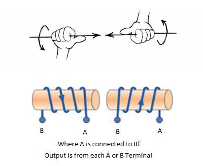
Any Electrical Engineer will tell you: "The way a Coil is wound does not make any difference to the System." This statement is not true. In my thread: Some Coils Buck and some Coils DONT, I gave experimental proof, the Winding Direction is important! 

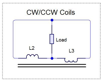
In this particular Circuit, Configuration Two in bucking mode appears to be the most beneficial! CW/CCW Coils.

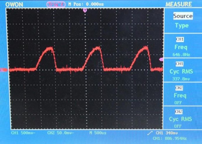
  • 0.680 volts RMS
  • 192.1 ma mean
  • 196.4 ma mean

Compared to where Bucking does not Work, not very well anyway:

  • 0.587 volts RMS
  • 55.18 ma mean
  • -19.97 ma mean

and the next best configuration after Configuration Two, Configuration One:

  • 0.624 volts RMS
  • 150.9 ma mean
  • 172.2 ma mean


There are three configurations:

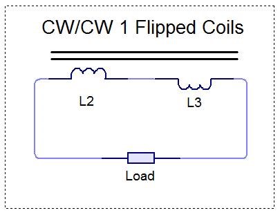
  1. Coils wound in a single direction in the same Axis.
  2. Coils wound in a single direction in the same Axis, but one Coil flipped End for End.
  3. Coils wound Clock Wise and Counter Clock Wise respectively in the same Axis.


NOTE: We have detailed Tariel Kapanadze's Grenade Coil and how part of the Coil is Non-Inductive by Definition, yet it Amplifies Voltage and Current many times! COP = ∞

The experiments I have shown, show the same basic things as others before me have:


@9 : 46 in the following Video, Listen, the Noise is a giveaway!


The most simple experiments are the most important! Every single machine I have ever seen, the Inventors all started with studding the Electrical "Generator", all of them!

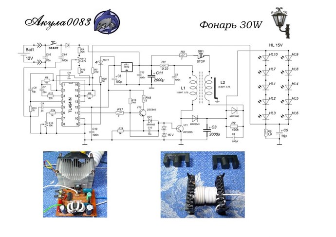
Akula, just before he got the Lanterns working: "ТПУ от акулы 0083 часть 2"


CLEMENTE FIGUERA

PRINCIPLE OF THE INVENTION - Watching closely what happens in a Dynamo in motion, is that the turns of the induced circuit approaches and moves away from the magnetic centers of the inductor magnet or electromagnets, and those turns, while spinning, go through sections of the magnetic field of different power, because, while this has its maximum attraction in the center of the core of each electromagnet, this action will weaken as the induced is separated from the center of the electromagnet, to increase again, when the induced is approaching the center of another electromagnet with opposite sign to the first one.

Because we all know that the effects that are manifested when a closed circuit approaches and moves away from a magnetic center are the same as when, this circuit being still and motionless, the magnetic field is increased and reduced in intensity; since any variation , occurring in the flow traversing a circuit is producing electrical induced current .It was considered the possibility of building a machine that would work, not in the principle of movement, as do the current dynamos, but using the principle of increase and decrease, this is the variation of the power of the magnetic field, or the electrical current which produces it.

The voltage from the total current of the current dynamos is the sum of partial induced currents born in each one of the turns of the induced. Therefore it matters little to these induced currents if they were obtained by the turning of the induced, or by the variation of the magnetic flux that runs through them; but in the first case, a greater source of mechanical work than obtained electricity is required, and in the second case, the force necessary to achieve the variation of flux is so insignificant that it can be derived without any inconvenience, from the one supplied by the machine. Until the present no machine based on this principle has been applied yet to the production of large electrical currents, and which among other advantages, has suppressed any necessity for motion and therefore the force needed to produce it.


The induced voltage in the winding obeys Faraday’s law as quantified by Neumann

Ref: Floyd Sweet - The Space-Flux Coupled Alternator.


Many others also! We have been told:


I am trying to tell you the same thing, I use reference to show I am only re-sharing something that others have already tried to share, at least in part.

The point here is the Curl of the known Fields and how this Curl can be represented! To get some idea, about the Curl:


The Right Hand Grip Rule can be applied in a few different ways, to predict Current, or Magnetic Field and even the Magnetic A Vector Potential.We must move down the the Core Level, pretend we are standing on the Core and can see the Curl.


If we are smart, and we are, then we can apply Electromagnetic Induction to every single Changing Magnetic Field, the Primary and the Secondary, where normally the Secondary is ignored.

Remember what we were told:


That is such an important statement!

The Coils each have a Current, and if we work the Currents such, that the Currents themselves make for a greater Primary Assist, also meaning the Primary magnetic Field is Greater, then we have exactly as Floyd Sweet Told us:

The current and potential windings require relatively little power, and are applied in such a manner
that rate of flow of moving charges may be accelerated beyond 1 ampere = 6.24 x 10¹⁸ electrons per second. Thus the duty factor of the copper changes.

I2R losses diminish and more charges drawn from the now coherent space field flow at a faster rate as current to the load. This means as more current is required by varying loads more feedback magnetomotive forces free more electrons from binding forces complimented by potential magnetic forces of the orientated, coherent space field. Thus a conductor that formerly had a temperature rise above ambient labelled as a factor of 10 would now operate at a temperature of 1.0. Thus the same gauge wire would carry 10 times more current at the same temperature. 

Even better results may be forthcoming. The energy conversion conservation is fantastic.


Your Input Coil only brings the Potential, or Voltage up, The Partnered Output Coils do all the work themselves! One Partnered Output Coil being the Coil on the Stator and One Partnered Output Coil being the Coil on the Rotor, each Coil only being excited by the Action, in our case we are replacing the Rotation of the Rotor with a small Changing Magnetic Field initially.

We have built a Solid State Electrical "Generator" - This is the best way to think of it.


Your Core can only hold so much Magnetic Field, your Coils can only have so much Current through them.

Best wishes,

   Chris

Chris posted this 17 April 2020

Welcome back Atti!

@Everyone, I have invited Atti to come back, we have had a discussion and we have come to an agreement.

Welcome back and Thank You for sharing Atti!

Best wishes,

   Chris

Atti posted this 19 April 2020

I forgot the drawing drawing.

Chris posted this 08 May 2020

My Friends,

At the Input, we have to remember, there is an Energy cost! 

When I did my MEG Replication, I read a passage that did not make a lot of sense:

The experimentally-measured data was extrapolated to describe operation at an input voltage of 100 volts, with the input current being 140 ma, the input power being 14 watts

Ref: The Meg Patent.


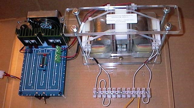
Seeing the big Heat Sinks and Fans on the Fets, I was surprised! See here:


What I am saying is, don't be scared to spend a little on the Input! Stay in your Switching Units Parameters! But don't be scared to use a little Input Power! Its important to get the Machine working!

You must remember, as your Machine moves into Resonance, your Input will drop off as a Function of the Magnetic Fields in the Machine! The Higher the Magnetic Fields, the more is sent back to your Input, meaning the LESS Input Power You Use!

Remember:

The VTA "likes" to always see a minimum load of 25 watts.

Ref: FLOYD SWEET'S VTA UNIT - by Walt Rosenthal


This is really important to see! Part of the Experiment! You need to get the Magnetic Fields working properly Together!


Best wishes, stay safe and well,

   Chris

Attached Files

Chris posted this 31 August 2021

My Friends,

A short video to show you that a simple Understanding is very important:


Here is some code, showing you a more advanced look at what is really going on:

// Ampers Force Law:
var AmperesForce = AmperesLaw.AmperesForceLaw(3, -3, 3, 0.1, 1);

/// <summary>
/// Ampère's force law
/// In magnetostatics, the force of attraction or repulsion between two current-carrying wires is often called Ampère's force law.
/// Equation: FM = μ0 * I1 * I2 * I3 * l / 2π * r
/// </summary>
/// <param name="CurrentA">Current in Wire A in Units of Amperes.</param>
/// <param name="CurrentB">Current in Wire B in Units of Amperes.</param>
/// <param name="CurrentC">Current in Wire C in Units of Amperes.</param>
/// <param name="Length">Wire Length in Units of Metres.</param>
/// <param name="Distance">Distance of Wires in Units of Centimeters.</param>
/// <returns>Fm a double containing the Force in Newtons (Kg m/s^2)</returns>
public static double AmperesForceLaw(double CurrentA, double CurrentB, double CurrentC, double Length, double Distance)
{
    // FM = μ0 * I1 * I2 * I3 * l/2π * r
    return ((Constant.VacuumPermeability * CurrentA * CurrentB * CurrentC * Length) / ((2 * Math.PI) * Distance));
}


Asymmetrical Force gives us: -5.4E-07 Kg m/s2

Symmetrical Force gives us: -1.8E-07 Kg m/s2

Yup, some PPL are a bit Dupid ha! See a problem here?

My Friends, this is very important, very basic Facts! Anyone disputing these very simple Facts is either Bought and Paid for Shills or Bought and Paid for Shills, no other options exist!

Best Wishes,

   Chris

Chris posted this 18 January 2023

My Friends,

Truth of the matter is: "Those ignoring the technology in this thread are either: Dumb or Ignorant"

Do the math:


Independent Replication = Scientific Proof and choosing to stay ignorant when the Answers are right in front of your eyes is stupidity!

Why do so many 'supposed' researchers choose to stay ignorant to the most simple, cheapest, Free Energy Machines ever! The reason is, they are not Genuine Researchers, they are Paid Disinformation Artists!

This thread gives you all the data you need to Succeed!

Best Wishes,

   Chris

Jagau posted this 09 October 2019

Sorry I thought it was a replication of melnichenko when he said this


Since the current in the coils of the same, we believe the resulting voltage in the time T2 is twice to the accumulation of energy
expended at the time t1.


Jagau

Chris posted this 09 October 2019

Hey Jagau,

I was called away, sorry.

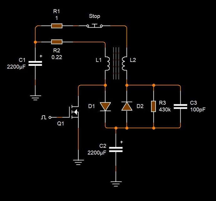
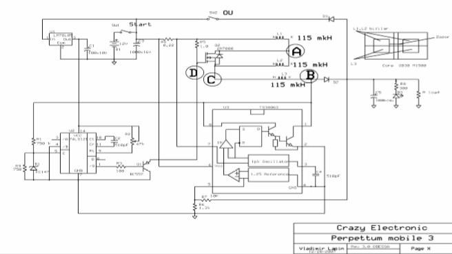
We have some open doors with the above circuit, it is not clear, and in-fact it is confusing as to its operation. I want to specifically show something. The Circuit above compared to this circuit:


We are looking at some circuit differences! In fact, we have several different Circuits in the document here: Генератор на нелинейной индуктивности

What we know to be true, is the Circuit used is more like this:


Which as we know was the working model, when it was stated:

A working model by Valery, free-energy@list.ru.

Improving the coach, you can create the perfect coach, but first-class car - barely. (Edward de Bono)

Energy generator in the nonlinear inductance

Developed and assembled the unit with an efficiency of greater than 1. Working in self-maintaining, with the releasing enormous amounts of energy it takes to glow lamps. Valery.


We know this to be in-accurate! We know from research the circuit was the Circuit pointed out above, and again here:


You can find a lot of data here: Akula's circuits- is this the principle?


The quote:

The essence of the research: obtain convincing theoretical, computational and experimental evidence for the possibility transgeneratsii electricity from non-additive (non-linear) properties of the energy of electromagnetic fields and waves. The experiments are quite simple and easily reproducible in any special laboratory. This work is the development of some interesting ideas about the physics of Tesla radio and the possibility of generating energy from non-linearity of the energy field. The work is not contrary to modern physics, electrodynamics, well grounded in theory.

Ref: Andrey Melnichenko - Common-mode interference of electromagnetic waves and transgeneratsiya energies.


The point, I am trying to make is, we must follow the path of proof. Proof, hard data is going to be where we make huge leaps forward like we already have!

The document: Transgeneratsiya electromagnetic field energy, make a huge effort to deal with Electromagnetic Waves and specifically:

So we see that for the addition of two opposite-traveling electromagnetic waves resulting electromagnetic wave power increases by four times.


The method of operation is Electromagnetic Waves in Opposition.

I hope this research helps some!

   Chris

Chris posted this 11 October 2019

My Friends,

Another Video, this time a bit of understanding on what we saw in the Experiment in the first video.


I hope this video is useful for all!

   Chris

Fighter posted this 23 October 2019

although every month im becoming more and more comfortable with the fact our planet does not have free energy products.  - because its really bloody difficult.

Not entirely true, Patrick. Our planet have free energy products, it's just those products are kept in military black projects and people are not allowed to have that. Yet. That's why we all are here, to change that.

Every time I see some news about UFOs flying in our planet's sky or in orbit it's a motivation to continue on this way, I'm telling myself "Those guys, no matter if they are our military or if they are just visitors, are powering their ships with free energy and have anti-gravity engines. It's everything right under our nose, they're showing us these technologies and the path we must follow...". 'Cause I'm 100% sure those ships don't have immense reservoirs with fuel on board to get the energy they need to do all the incredible things they do in our skies.

So no, the only reasons we civilians don't have free energy (yet) it's not because this planet don't have the technology, it's just because some greedy morons want to keep that technology just for themselves even if they obtained it in black projects using trillions of dollars took from our civilian pockets.

Fighter posted this 27 October 2019

Yep, they're talking directly about bucking-coils and I recognize a ZPM schematics there. It's funny how that guy "remembers" about a paper he "wrote" few years ago about bucking-coils. Sure, buddy, whatever you say... laughing

(link to larger image here)

And this guy Smudge reminds me of someone we had here who refused to share his work but was very ironic and acted like know-it-all, don't say who Sure buddy, you "did" a lot of research and put a lot of "effort" in renaming from "Romanian ZPM" to "Magnetic Delay Transformer", congrats ! laughing

(link to larger image here)

Let them copy, there is a higher-purpose in what we do here, don't care if these copycats give us credits or not...

Chris posted this 30 October 2019

Hi Dewetw,

I would say pretty close wink

The Time Rate of Change of the Magnetic Field of the Primary Coil ( 25 turns on mine ), Induces a Voltage ( V ), and because we have a Load, a Current ( I ) in one Secondary Coil.

The Time Rate of Change of the Magnetic Field ( Current ( I ) in this secondary ) creates a Voltage ( V ) in the Tertiary Coil and because we have Loaded Conditions, we have a Current ( I ). Both Secondary Currents Oppose each other, however one Current assists the Primary.

The time, I marked in the video @ 38 : 18:


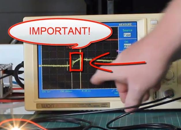
Is Important! 

This is where the Input Coil can bring the two Output Coils to maximum Amplitude as quickly as possible! This means we must look for this optimum point, Magnetic Resonance. Magnetic Resonance, where each Coil's Current is 180 Degrees out of phase, like we saw in The Mr Preva Experiment.

This point is where the two Coils reach Maximum Amplitude in the shortest possible time, the slap together, we have no Impedance of the Coils!

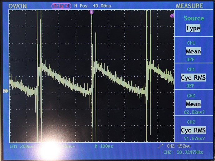
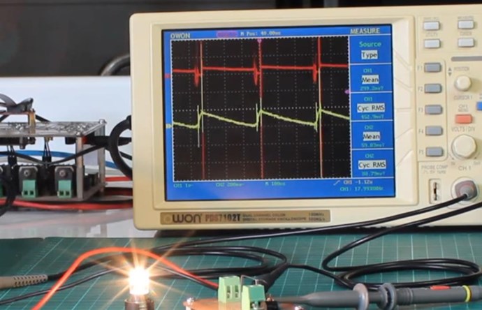
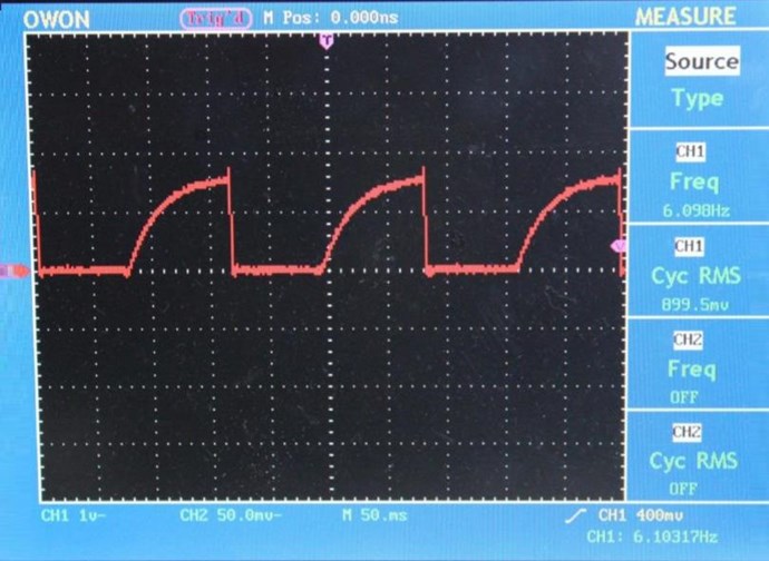
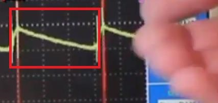
Here is one Cycle, marked in Red:

You can see the Ramp Up, or the Slap Together, this is important, it must be short, fast and have a good amplitude.

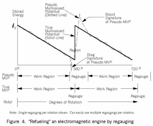
Compare to Tom Bearden's Asymmetrical Regauging:


We see a match.

   Chris

Vidura posted this 31 October 2019

Good experiment dewetw, as you asked for improvement I would suggest to reduce the primary turns and use a thicker wire gauge, so you can take better advantage of your fast Switching circuit, and get the voltage higher. Regards Vidura.

Chris posted this 07 November 2019

My Friends,

The evolution of the human race, is paramount! The first most important thing, over and above all else!

Some of the greatest minds have come and gone, left our small planet with tall dreams, giving the young hope and inspiration, these people have changed the world:


The problem is, there is far too much procrastination! To many do not believe in our future.

We humans, MUST start pushing greater boundaries. We must release the Limits we place on ourselves, and we must evolve.

Electrical Energy is at the forefront of our evolution! Manufacturing costs are detriment to Electrical Energy Costs.

We have some answers, we have already removed some Limits. Many breakthroughs have already been made. I cant do this by myself, I need you all to do it with me! To help me, to assist, to break through the Limits we must not let ourselves be bound to!

This and other threads here on this forum and material on my site: www.hyiq.org is here to help all.

Please, we must evolve! 

   Chris

Chris posted this 09 November 2019

Hey Vidura,

My Friend, you are very wise! I have said a few times now wink

Thank You!


@All I have a new video, just a look at what we got in Video Seven:


I hope this helps some!

   Chris

Chris posted this 09 December 2019

My Friends,

Independent Replications have been done, some are above-unity, some on the verge. None the less, what I have shown has also been successfully replicated by other Members of this forum! With a little more work, Members will improve their Machines!

Please join in, help us change the world!

CaptainLoz last experiment is a taste of what you can achieve:


We are here to help you, join us, and we can help!

Fighters work, The Romanian ZPM,  is also another way to use the same technology, its also an excellent example of above-unity.

Please understand, this is only the start, its a taste of whats achievable!

The other forums are so far behind, We are Light Years Ahead!

You are Safe Here, we have Zero Trolls!

   Chris

Chris posted this 12 December 2019

My Friends,

How close can people get without realising what they actually have?

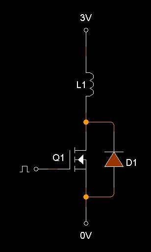
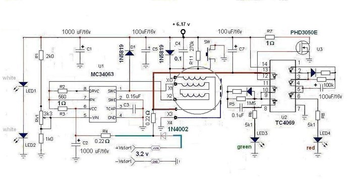
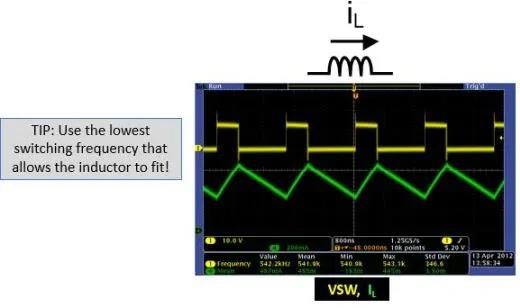
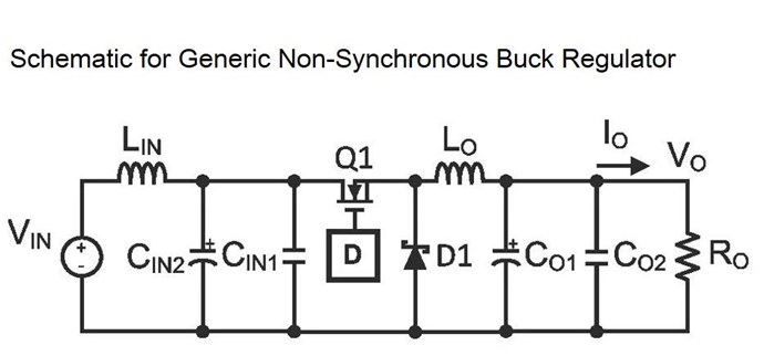
I read an article the other day, just by coincidence, I came across the image, so i read the article: The Buck Regulator – Power Supply Design Tutorial Part 2-1

Look how close they get without realising the next step in the Earths most Important Problem: Energy "Generation"


His circuit is not far from ours:


If this guy saw our work, he would say I was so close!

Ask yourself, what can this Coil do:


If it had a Partner, what could they do? What could they do if they were both bought into Magnetic Resonance?

   Chris

We're Light Years Ahead!
Members Online:

No one online at the moment


What is a Scalar:

In physics, scalars are physical quantities that are unaffected by changes to a vector space basis. Scalars are often accompanied by units of measurement, as in "10 cm". Examples of scalar quantities are mass, distance, charge, volume, time, speed, and the magnitude of physical vectors in general.

You need to forget the Non-Sense that some spout with out knowing the actual Definition of the word Scalar! Some people talk absolute Bull Sh*t!

The pressure P in the formula P = pgh, pgh is a scalar that tells you the amount of this squashing force per unit area in a fluid.

A Scalar, having both direction and magnitude, can be anything! The Magnetic Field, a Charge moving, yet some Numb Nuts think it means Magic Science!

Message from God:

Hello my children. This is Yahweh, the one true Lord. You have found creation's secret. Now share it peacefully with the world.

Ref: Message from God written inside the Human Genome

God be in my head, and in my thinking.

God be in my eyes, and in my looking.

God be in my mouth, and in my speaking.

Oh, God be in my heart, and in my understanding.

Your Support:

More than anything else, your contributions to this forum are most important! We are trying to actively get all visitors involved, but we do only have a few main contributors, which are very much appreciated! If you would like to see more pages with more detailed experiments and answers, perhaps a contribution of another type maybe possible:

PayPal De-Platformed me!

They REFUSE to tell me why!

We now use Wise!

Donate
Use E-Mail: Chris at aboveunity.com

The content I am sharing is not only unique, but is changing the world as we know it! Please Support Us!

Thank You So Much!

Weeks High Earners:
The great Nikola Tesla:

Ere many generations pass, our machinery will be driven by a power obtainable at any point of the universe. This idea is not novel. Men have been led to it long ago by instinct or reason. It has been expressed in many ways, and in many places, in the history of old and new. We find it in the delightful myth of Antheus, who drives power from the earth; we find it among the subtle speculations of one of your splendid mathematicians, and in many hints and statements of thinkers of the present time. Throughout space there is energy. Is this energy static or kinetic? If static, our hopes are in vain; if kinetic - and this we know it is for certain - then it is a mere question of time when men will succeed in attaching their machinery to the very wheelwork of nature.

Experiments With Alternate Currents Of High Potential And High Frequency (February 1892).

Close