Moving into the Future with Partnered Output Coils

  • Topic Is Sticky
  • 1.2K Views
  • Last Post 29 July 2019
Chris posted this 24 July 2019

My Friends,

Your task, should you choose to accept it, is to make Two Coils buck, when driving with a third:


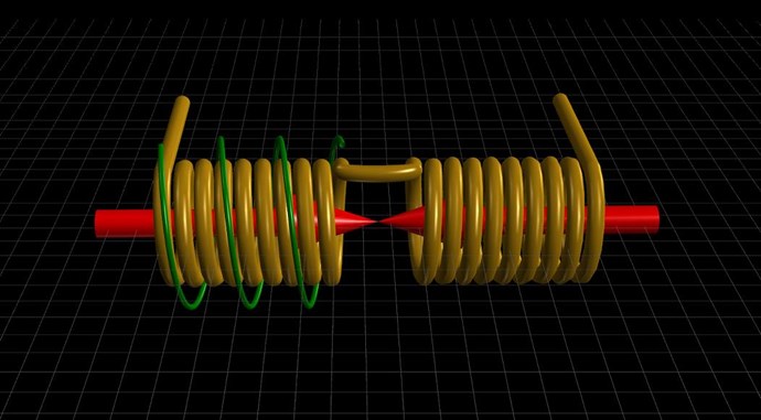
Your Partnered Output Coils are your Target, the goal is to bring them into Magnetic Resonance.

Using the detailed information from:

  1. Parallel Wire or Bifilar Coil Experiment
  2. Delayed Conduction in Bucking Coils


You should have more than enough information to make this work! I will work with you, to help you make this work, other Members here will also assist you in this task.

As you will already know, many ways exist to implement Delayed Conduction:

  • A Mosfet.
  • A Triac.
  • A TVS.
  • A MOV.
  • Even a Slow Turn on Diode can be used...
  • Lots of things can achieve this task...


I must warn you, it's not easy, there is some fiddling, it takes patience, it takes skill, it take study and understanding, but every single soul on this planet can do it!

A basic starting Circuit is as follows:


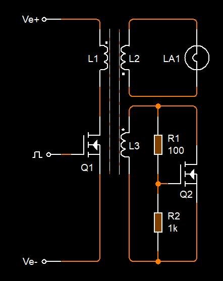
NOTE: Every single EE in the world is taught that this is not how you implement a Circuit, it all has to be clean switching, all symmetrical, Delayed Conduction is a big no-no in this sort of configuration! If you read this and only learn one thing, take this as the most important fact!


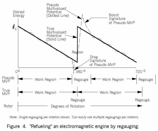
Once you have done this once, it becomes easier and easier every time, as long as you have done the study, done the hard work to understand it.

When you achieve this task, Magnetic Resonance, we can turn this into Asymmetrical Regauging, if you have not already, and then you will have:

An Above-Unity Energy Machine!


This goal is completely up to you, but please remember I have shown for a long time, independent replications:


of what I am sharing with you, and remember, what I am sharing, is not new, many others out there have demonstrated machines like this:

  • Floyd Sweet VTA
  • Don Smith
  • The MEG Team
  • and many more...


CD-Sharp has the most advanced experiment on this forum to date. Like many other Members here, he is very qualified for questions!

The reason we do not have this mainstream is simple, mindset, we already think we know everything, I am here to tell you, we most certainly do not!

Please create your own Threads for Replications, if you like, put your PayPal Support Buttons at the top of the page, and we will help you build your own Above-Unity Energy Machine! 

Much to learn, little time left...

   Chris

Order By: Standard | Newest | Votes
Jagau posted this 24 July 2019

Hello Chris


What is the ferromagnetic material that you suggest,
Ferrite core, air core, iron core or metglass?

And I see that for replication we have to create our own thread.

Jagau

  • Liked by
  • Chris
Chris posted this 24 July 2019

Hey Jagau,

I have had little luck with Air Core, not to say others wont either...

I would say use what ever is laying around, Laminated Iron Cores will almost definitely need an air gap.

I have as a side project two old Laminated EI Iron Core Transformer I am attempting a build on. Not sure it will work, I am going to use the E's and remove the I's, backing the two E's together with a small gap, I cant see why it wont work.

I have used Ferrite, I have used Metglas, both work, both work fine. So I guess as long as the Magnetic Fields can propagate, not be held steady or slowed down too much, as in the gradient on the Core, or the rise time, then we should have a very good chance of making a Laminated E Core work.

Different materials do have different BH Curve speed ratings as you know, Iron being one of the slowest, but what we are doing does not require a Full BH Curve.

I hope this is coherent, no coffee yet.

   Chris

  • Liked by
  • Jagau
  • cd_sharp
Jagau posted this 24 July 2019

Ok, thanks for answering me

So I will try this basic circuit with a ferrite core,
 I already had success with the potcore, so I will continue with this one.
I will keep the natural capacitance of the coils and I will use 3 coils including two in POC

jagau

  • Liked by
  • Chris
  • cd_sharp
Chris posted this 24 July 2019

Hi Jagau and other Readers,

Of course, the trick is to get the Switch clean with good timing. If the switch is not switching properly, then the Coils can not buck, meaning this can not work. I know you know this already but wanted to take the opportunity to make this clear for other Readers.

This does take some commonsense and some fiddling as you know. wink

   Chris

  • Liked by
  • cd_sharp
Chris posted this 25 July 2019

Hey CD,

I guess this would be a yes, I haven't really thought about it this way before.

Of course the Coils will have a different potential on the terminals all the time, Currents can not flow all the time, Voltage decreases.

Hmm, pondering...

   Chris

  • Liked by
  • cd_sharp
Jagau posted this 25 July 2019

Hi Chris

It is the quality factor Q that motivates me to use the natural capacitance of a coil.

Remember that when adding an external capacitor there will be a capacitive reactance Xc add to your coil so extra resistance to the resonance frequency, so lower Q


Tesla has explained in his various patents why he used to know the self capacitance of a coil.

Anyway at a very low frequency it can be ignored being given that it is very low value.

Jagau

  • Liked by
  • cd_sharp
  • Chris
Chris posted this 27 July 2019

Hi Jagau,

Yes I have read many of Tesla's patents.

We both know Magnetic Flux has a defined quantity per unit area, B, and is calculated as follows:  B = μ0nI

Where, n is the number of loops per unit length ( l ) of the solenoid ( n = N/l ), with ( N ) being the number of loops and ( l ) the length.

I always say, NI is the Ampere Turns ( AT ), makes for an easier understanding. If length ( l ) = 1.0 then it is.

Please forgive me, but for every unit of current we put through Turns ( N ) on the Magnetic Field Creation state, at absolute maximum Q, in a LCR Circuit, we can only ever get back what we put in, would you agree?


Because Damping ( ζ ) = 1 / 2Q. The best possible LCR Circuit can only ever reach 90 Degrees: Q / j.

Q is related to the damping ratio ζ, which is related to the phase lag at resonance. Therefore, we first find the resonant frequency ωr and then find the phase lag φr at resonant frequency. Q can then be calculated by Q = tan φr/2.

Ref: Mechanics of Beam and Diaphragm Structures


Ref: Formula Sheet for Circuit Analysis

Sorry for my rant, its the kafuffle that is spread across the net about this topic at the moment. 


I would have to say, we still need a method of a Persisting Magnetic Field beyond our Input, a Work Region if you like, that we do not pay for, if we are going for Excess Energy:


I hope I have made some sense here!

   Chris

  • Liked by
  • Vidura
  • cd_sharp
Bogdan2k posted this 27 July 2019

Hi Chris,

I`d like to try a replication of your POC and I have a few questions, if you be so kind to help me, it would be much appreciated.

-if I try the for the core a ferrite rod the effect is the same (I have some around and it`s much easier to wound them) (or do I need a closed loop core?)

-if the primary coil and/or the secondaries are wounded bifillar (I`ll wound them this way and connect 1 or 2 wires parallel and series to see the difference), it would be beneficial?

-if I drive the primary coil on the high side ( 

) it would be beneficial?

-have you tried connecting a FWBR to the loaded secondary, drive the load on DC and measure this way?

-on the circuit schematic, the second picture from your post, you present the second secondary with a mosfet in self oscillation mode, but what is the voltage rise this way, on the secondary? I don`t think it could be too much, I`ll give it a try first with a TVS, I think I have some at 100-200V breakdown voltage ( I saw this one is unidirectional)

-the driving signal is square wave, right?


Thank you!

  • Liked by
  • Chris
Chris posted this 27 July 2019

Hello Bogdan2k and welcome!

First and perhaps most important suggestion is forget about the Voodoo Science pushed by others out there - Its rubbish! - ALL Energy is Radiant!

My PM explains this.

Study the Electrical "Generator", because it is truly a pump. I have a 101 series on this, here: Electrical Energy

Energy is pumped, Time Varying Magnetic Fields, plural, achieve this task!

Your task, should you choose to accept it, is to make Two Coils buck, when driving with a third:


This means, you have three Magnetic Fields changing in Time. The trick is to make the third Magnetic Field assist your input, not work against it!


You're on the right track so far:

-if I try the for the core a ferrite rod the effect is the same (I have some around and it`s much easier to wound them) (or do I need a closed loop core?)

Closed or semi closed core, open core, yes it still works, as long as the coils can see a rise time of the Magnetic Field.


-if the primary coil and/or the secondaries are wounded bifillar (I`ll wound them this way and connect 1 or 2 wires parallel and series to see the difference), it would be beneficial?

I prefer two separate coils, one beside the other, bifilar is a very confused degraded term. All the machines I have ever shown show two separate Output Coils.


-if I drive the primary coil on the high side ( video ) it would be beneficial?

Yes, High side switching can be of benefit, but not always. Geometry, or operation may require one or the other.


-have you tried connecting a FWBR to the loaded secondary, drive the load on DC and measure this way?

We have performed many experiments, yes at one point we did work with this.


-on the circuit schematic, the second picture from your post, you present the second secondary with a mosfet in self oscillation mode, but what is the voltage rise this way, on the secondary? I don`t think it could be too much, I`ll give it a try first with a TVS, I think I have some at 100-200V breakdown voltage ( I saw this one is unidirectional)

The Mosfet's state, shown again here:


Is entirely dependant on the polarity of the Coil, only switching on properly when the Voltage is sufficient to turn on the Mosfet.  This image is only for guidance, and values may need to be changed, or circuit modification may even be required to some degree. The basic idea is there however. Yes, a TVS or MOV, many other ways to achieve this!


-the driving signal is square wave, right?

Yes, a Mosfet is typically a square wave device, but the result on the Coil may not always be a square wave.

The fast, but delayed, turn on of the second Partnered Output Coil is a requirement, it has to be fast, to assist the Input Coil do what its doing, short input pulse for a long output pulse:


Increasing the work region, where our Partnered Output Coils Pump Energy for much longer than we input energy! Asymmetrical Regauging!


Ask yourself the question: Every time, when three is involved, in a symmetrical exchange, what side must the third take?

What is our control mechanism? Delayed Conduction with a difference in Mutual Coupling.


   Chris

  • Liked by
  • Jagau
Jagau posted this 29 July 2019

Hi Chris
what I had in mind was that

a higher Q has a lower rate of energy loss compared to the stored energy

of the central frequency of the more restrictive bandwidth.

It was only that

sorry I could not answer before I left 3 days outside

Jagau

  • Liked by
  • Chris
We're Light Years Ahead!
Members Online:

No one online at the moment


What is a Scalar:

In physics, scalars are physical quantities that are unaffected by changes to a vector space basis. Scalars are often accompanied by units of measurement, as in "10 cm". Examples of scalar quantities are mass, distance, charge, volume, time, speed, and the magnitude of physical vectors in general.

You need to forget the Non-Sense that some spout with out knowing the actual Definition of the word Scalar! Some people talk absolute Bull Sh*t!

The pressure P in the formula P = pgh, pgh is a scalar that tells you the amount of this squashing force per unit area in a fluid.

A Scalar, having both direction and magnitude, can be anything! The Magnetic Field, a Charge moving, yet some Numb Nuts think it means Magic Science!

Message from God:

Hello my children. This is Yahweh, the one true Lord. You have found creation's secret. Now share it peacefully with the world.

Ref: Message from God written inside the Human Genome

God be in my head, and in my thinking.

God be in my eyes, and in my looking.

God be in my mouth, and in my speaking.

Oh, God be in my heart, and in my understanding.

Your Support:

More than anything else, your contributions to this forum are most important! We are trying to actively get all visitors involved, but we do only have a few main contributors, which are very much appreciated! If you would like to see more pages with more detailed experiments and answers, perhaps a contribution of another type maybe possible:

PayPal De-Platformed me!

They REFUSE to tell me why!

We now use Wise!

Donate
Use E-Mail: Chris at aboveunity.com

The content I am sharing is not only unique, but is changing the world as we know it! Please Support Us!

Thank You So Much!

Weeks High Earners:
The great Nikola Tesla:

Ere many generations pass, our machinery will be driven by a power obtainable at any point of the universe. This idea is not novel. Men have been led to it long ago by instinct or reason. It has been expressed in many ways, and in many places, in the history of old and new. We find it in the delightful myth of Antheus, who drives power from the earth; we find it among the subtle speculations of one of your splendid mathematicians, and in many hints and statements of thinkers of the present time. Throughout space there is energy. Is this energy static or kinetic? If static, our hopes are in vain; if kinetic - and this we know it is for certain - then it is a mere question of time when men will succeed in attaching their machinery to the very wheelwork of nature.

Experiments With Alternate Currents Of High Potential And High Frequency (February 1892).

Close