Measurement Block PCB

  • Topic Is Sticky
  • 2.7K Views
  • Last Post 24 January 2024
Chris posted this 02 March 2020

My Friends,

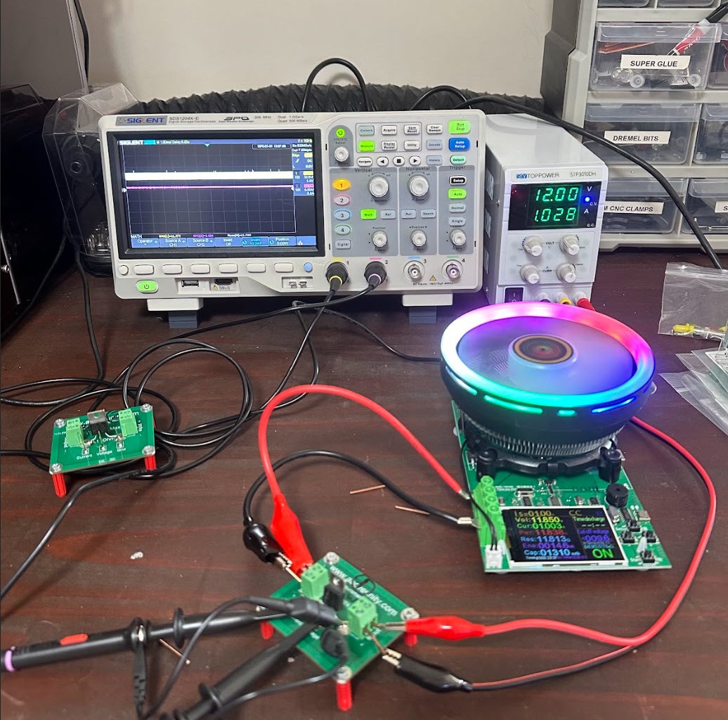
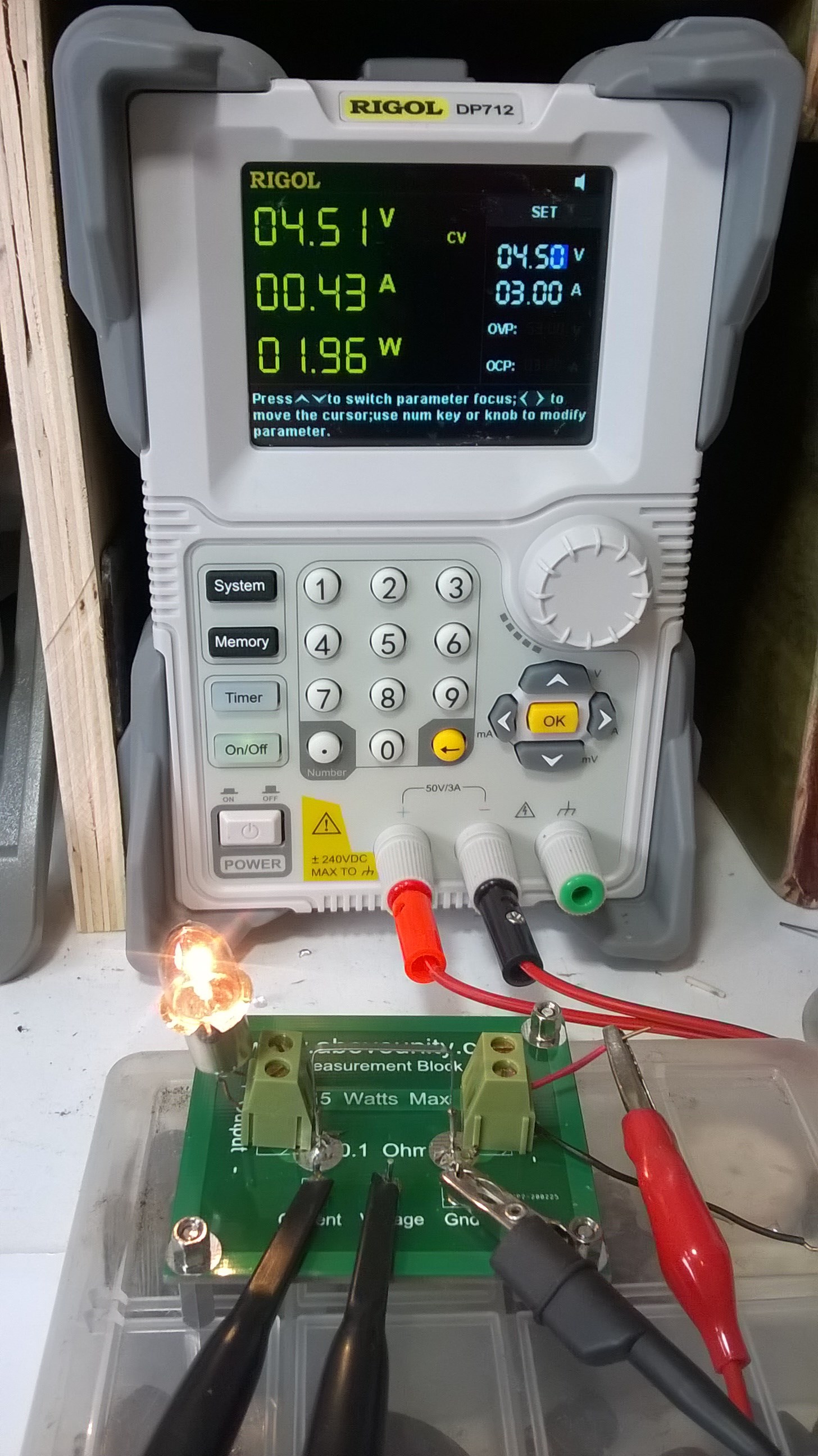
Observing what your Voltage Current is doing in your Machine is super Important, I have said all along, look at your Currents! Your Current is where you get an idea on whats going on!

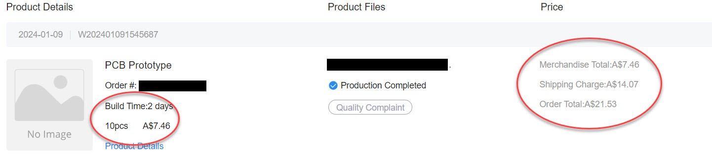
If you are interested in the Barebones PCB or a Kit, please visit E-Bay for purchase.

I have listed the

Barebones PCB:

  • Just a single PCB, you purchase the parts and build your self.


I also have the:

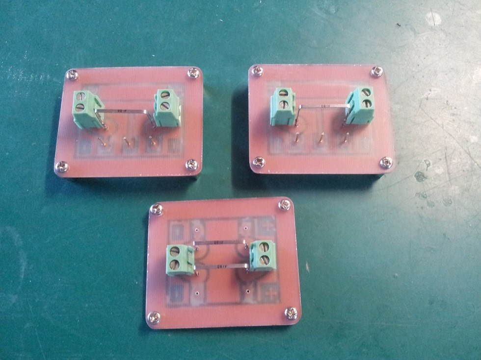
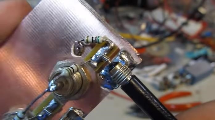
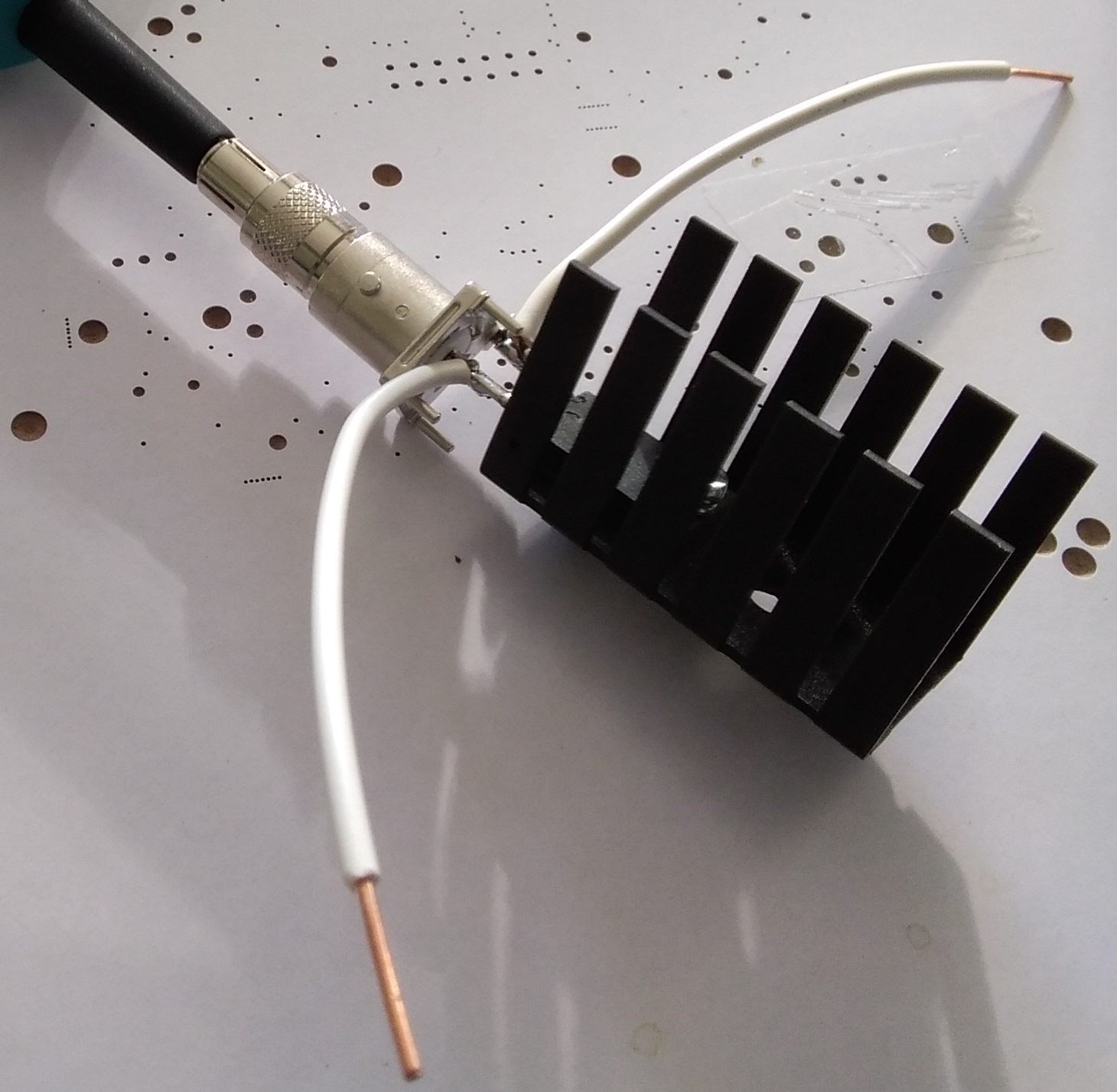
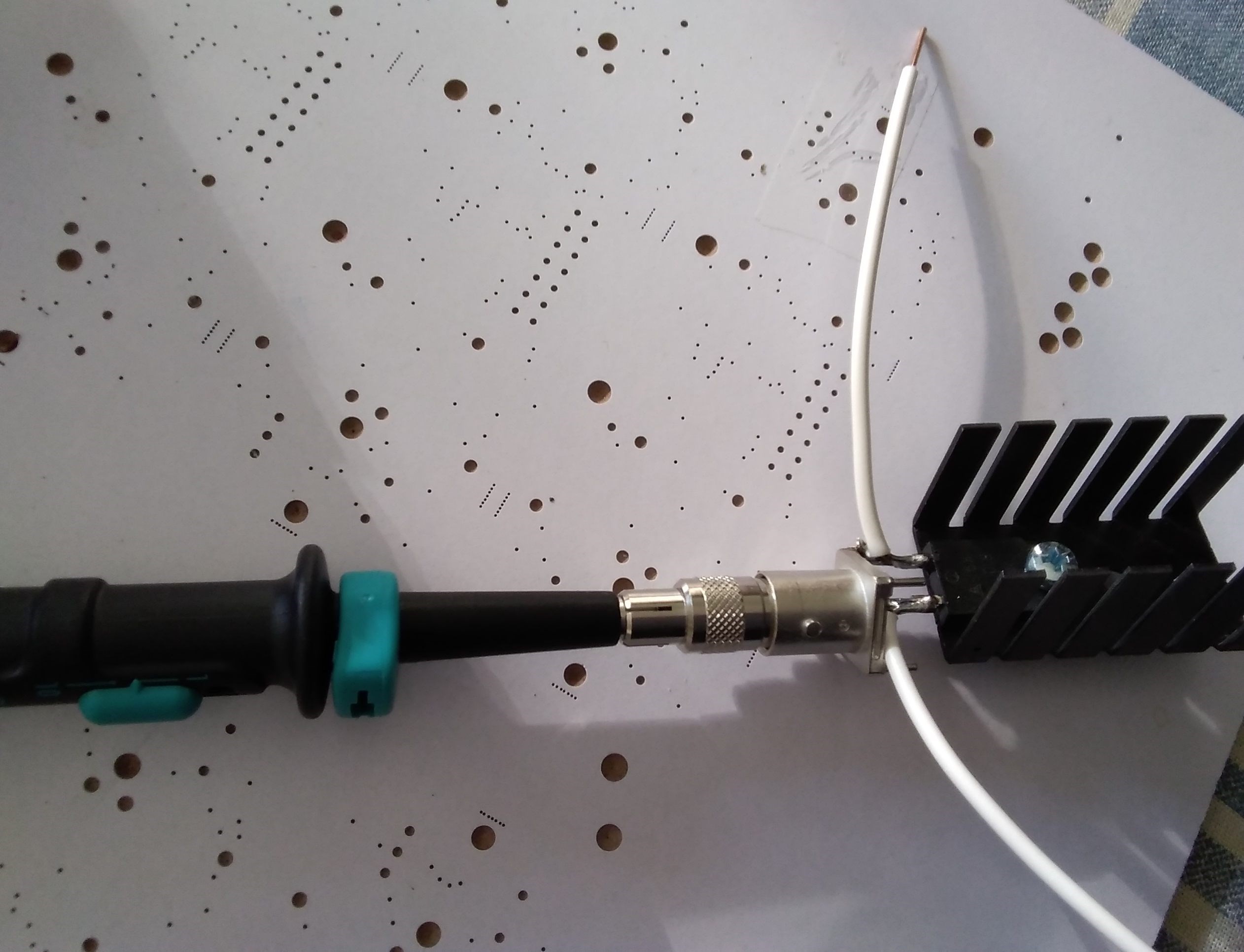
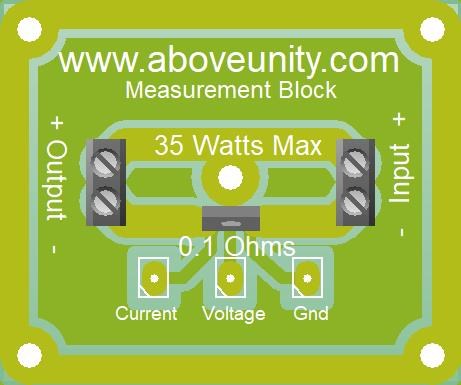
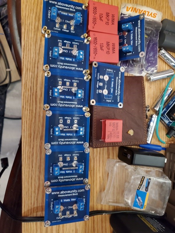
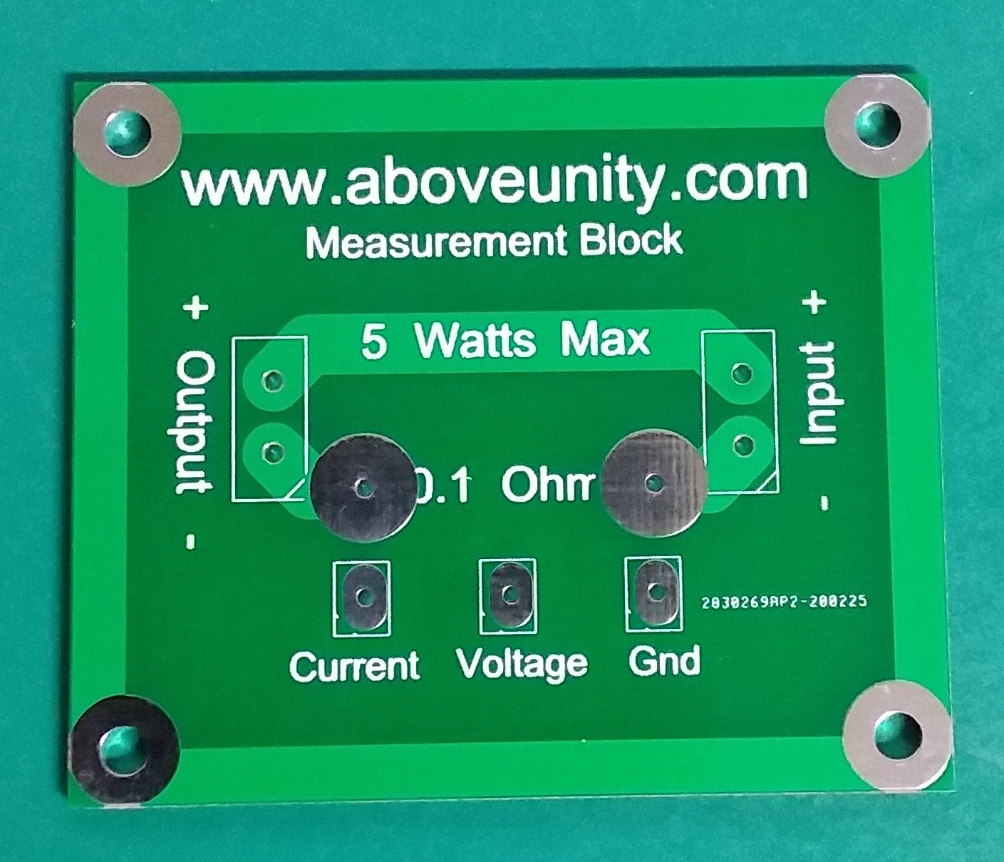
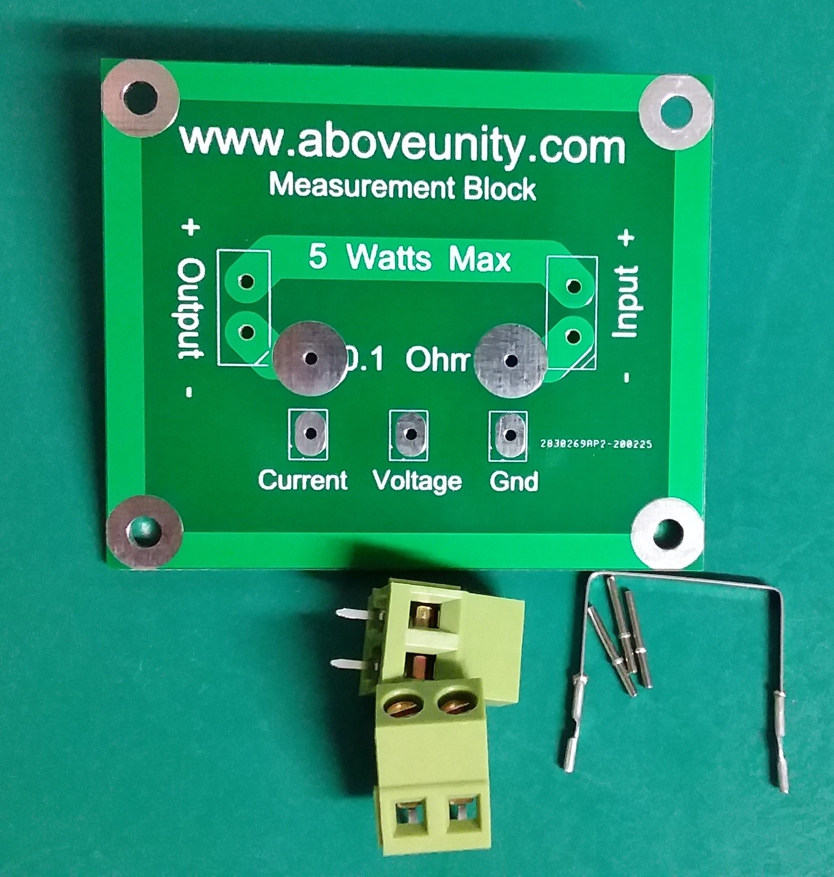
Measurement Block Kit:

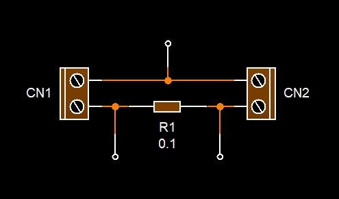
  • 2 x two pin terminal blocks.
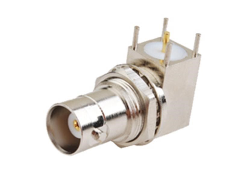
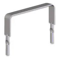
  • 3 x Matrix PCB Pins.
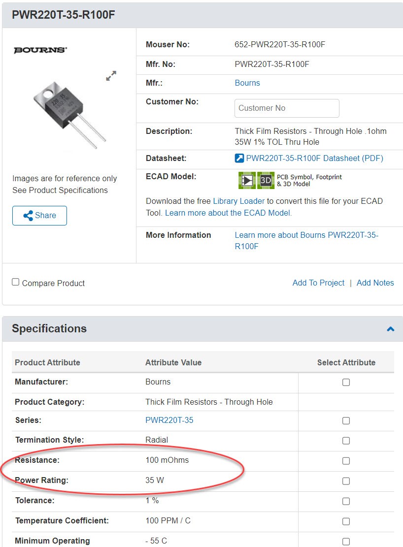
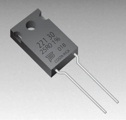
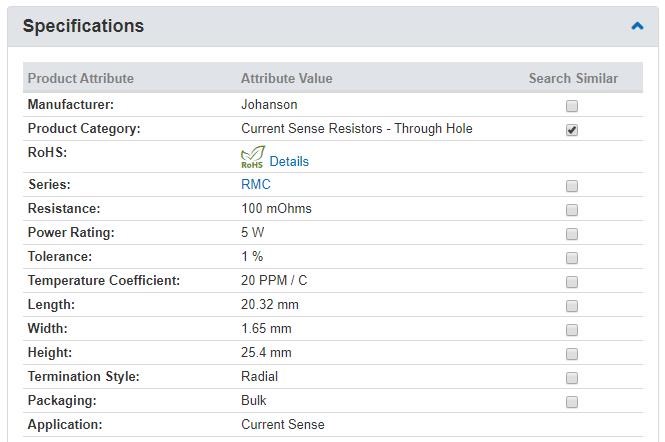
  • 1 x Through Hole Resistor 0.1 Ohms 1% tolerance.
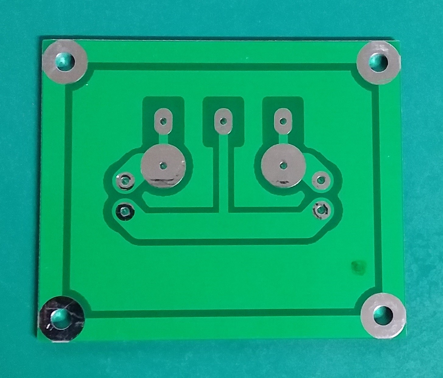
  • 1 x PCB for mounting the components.


This Item has been one of my most useful of all. 5 Watts is the Maximum Power, but please remember if you are using Pulsed DC peak power can be higher. 5 Watts is constant power maximum.

The Resistor is rated as follows:


All PCB's are based on the following Circuit:


Video Tutorial:


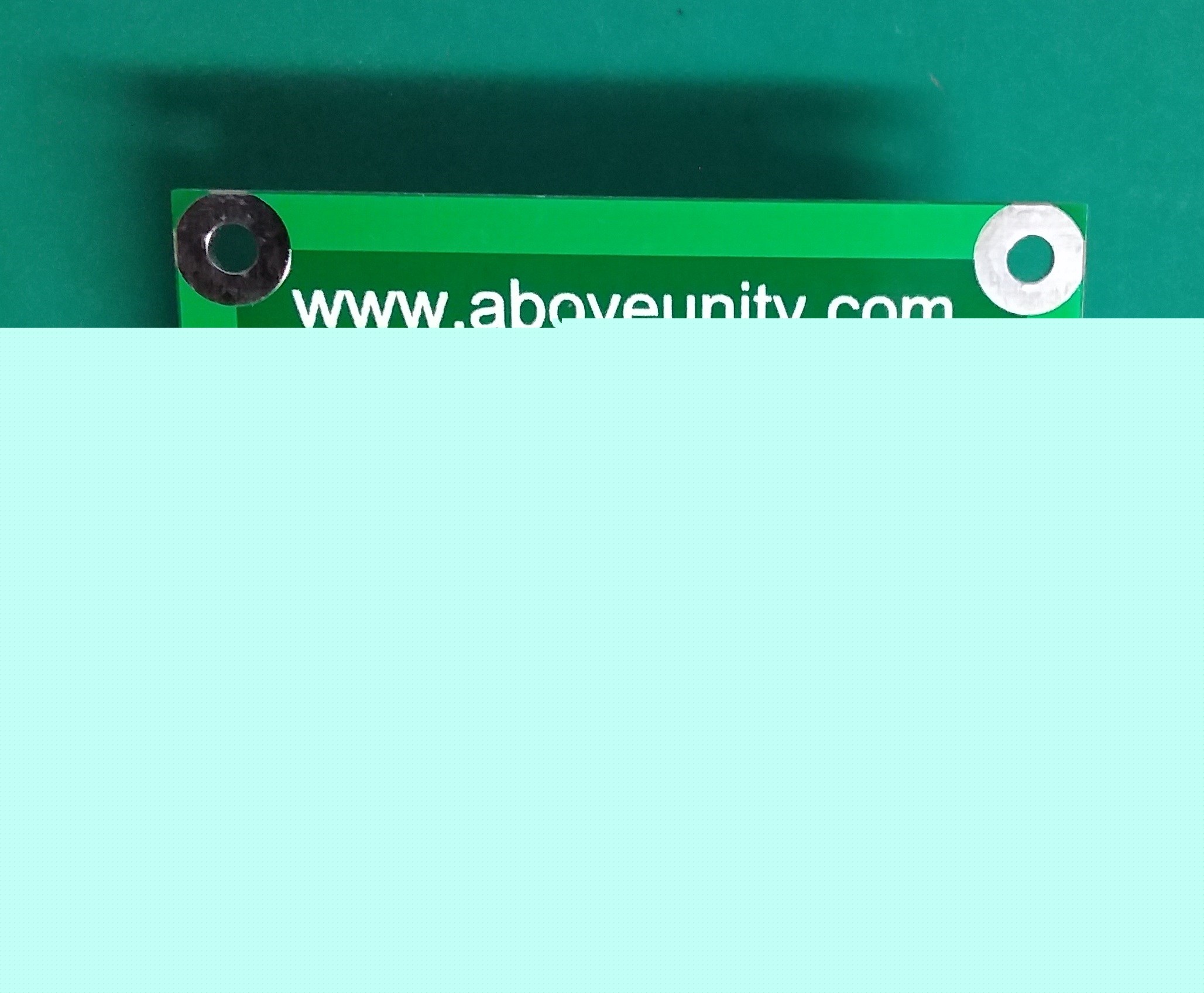
If you want to, you can also round the corners of the board for rounded edges. Something I often do.

Best wishes,

   Chris

Order By: Standard | Newest | Votes
Tinker posted this 24 January 2024

Thanks Chris/Marcel.  After I'd posted I found the Measurements thread and exactly what you guys are saying! I've now spent quite a bit of time on this, here and across YouTube so looking forward to some more practical tests. As always thanks for your advice and guidance


Neale 

  • Liked by
  • Augenblick
  • FringeIdeas
Chris posted this 23 January 2024

My Friends,

Marcel is absolutely correct!

If you are using a chopped DC Input, you absolutely need to use Mean or Average readings on the Scope!

Using RMS is 100% wrong and we all need to know why it's wrong to use RMS. We have covered this in detail in many places, but here in our Measurements Thread is one place to start. It is important to understand why somethings need to be done in a specific way, so you can be confident in your results! My YouTube Channel has a video or two on this also! There is no lack of information explaining why this is necessary!

Best Wishes,

   Chris


FringeIdeas posted this 23 January 2024

Hey, nice setup. I had a few similar resistors, cost me about 8 eur each. I should have got the boards too because it didn't take long and the legs broke off the resistors.

To answer your questions, quick and dirty as I think this might not be the best place for measurement talks.

All measuring devices are going to be slightly different. I would just make sure when you are making comparisons, for example input vs output, you use the same device.

As far as measurements are concerned, this link is actually in the builders guide.

https://www.aboveunity.com/thread/measurements/

And this video talks a bit about it.

Super short explanation, so you know what to look for. RMS will include (adds) negative swings. Mean averages out negative swings. So on our output, negative swings do mean energy used, so we want to include both positive and negative swings, so we use RMS to give us that total. On the input, if we have a negative swing that is energy being sent back to the power source, not energy being used. So using Mean on the input will give us a correct total energy spent after a full cycle is complete.

Hope that helped!

Marcel


Tinker posted this 23 January 2024

Hi all, just an update on the measurement block availability and sourcing from an AU perspective.  As per the details above I was able to register and upload the file to JLCPCB with no issues ( https://jlcpcb.com  ).  I ordered on 9th Jan and they arrived on 15th Jan from China for a total cost of AUD$21.93 for 10 boards! They must have had some sort of deal going as I was surprised at how cheap they were, 10 boards for AUD$7.46 + shippingJLCPCB 1

Sourcing the components was a little more challenging as the metal strip CSR listed was no longer available. I got all the parts from Mouser (https://au.mouser.com/) and opted for the more expensive 35W 0.1Ohm  https://au.mouser.com/ProductDetail/652-PWR220T-35-R100F which I'm testing at the moment.

CSR

As a newby I'm pretty happy with these and certainly have a few spare. I do have a question with regard to testing if I may? I have the Siglent 1204x-e scope and have channel 1, 2 and Math set up as per instructions in the video. My question is with regard to which value to use on the scope. I'm currently using the RMS value for both voltage and amperage which seems correct and the Mean for the Math. My main issue is that my power supply (cheap) shows a different reading to my meter that is different to my scope.  I've calibrated the scope so working off the assumption this is correct.  I also had a battery load tester (from my Bedini testing days) which helped so ready for next stage. 


Setup

Thanks again Chris for making the measurement blocks available.

regards

Neale  

Chris posted this 22 January 2024

Hello Brodonh,

Dude, please read this thread! It's all here in this thread, already explained, many times.

Sorry if I am coming across somewhat cranky, but my patience for lazy people is at an all-time low.

All you have to do is read and study, because I can't do it for you. I have even given you all a Read Button to make this easier.

This link helps you understand the forum: Help with using the Forum.

Good Luck, with a little effort, you will find the files and the instructions very easily!

Best Wishes,

   Chris

  • Liked by
  • Augenblick
brodonh posted this 21 January 2024

Where do I down load the Gerber files?

Thanks,

brodon

  • Liked by
  • Chris
  • Augenblick
anarsu posted this 07 November 2023

Oh okay. Thanks, Chris. I'll share this info with them.

  • Liked by
  • Chris
  • Augenblick
Chris posted this 06 November 2023

Hey Anarsu,

In the thread, I posted the details you need, Here.

What you will need to know:

Dimensions: 51mm x 61mm

File: .gb0 -  Board outline layer

File: .gb1 -  Bottom copper (solder side) layer

File: .gb2 - Top copper (component side) layer

File: .gb3 - Bottom (solder side) solder mask layer

File: .gb4 - Top (component side) solder mask layer

File: .gb5 - Silk screen (component outline) layer


Not sure why this is, the PCB Companies don't look at the inf file, it is all in there.

Best Wishes,

   Chris

anarsu posted this 06 November 2023

Hey Chris,

I submitted the gerber files on pcbway.com and placed an order.

They have come back with a question. Posting it here for your help /answer. Thanks!

------------ Question ------------

There is the engineer question for W466056AS1S1_35f2477b-e58f-4fb7-9075-ac8d01501ba2_power-block-gerber-files.zip.

As shown in the pic, our engineer cannot recognize the layer, plz make sure the file including the correct layer name file ( the copper layer, mask layer, drill layer, silkscreen layer) then send the new file for checking.

And they attached this image:

  • Liked by
  • Augenblick
anarsu posted this 26 October 2023

Thanks for your response, Chris! Great to see you active!

I've placed an order for the components. Got this for duty cycle - NE555 Pulse Frequency Duty Cycle Adjustable Module Square Wave Signal Generator.

Also, uploaded the gerber zip on a local website (robu.in) that manufactures custom PCBs :-D

The vendor was asking for the exact diode & capacitor number. I couldn't catch that from the videos so far. Will look again. If component specification is mentioned in any of the threads, please do point me there. I found resistor specification. Thanks!

More updates when I receive the components and the PCB!

  • Liked by
  • Augenblick
  • Chris
Chris posted this 21 October 2023

Hello and welcome Anarsu!

Yes, you can download the measurement block as gerber files, in a zip file, and send them to your favorite PCB Manufacturer. I believe this thread, if you read through, you will find instructions.

Thank You for your kind words, its time for us to change and for all peoples of the world to become what we were meant to be, one big, happy, self sufficient family!

Welcome My Friend!

Best Wishes,

   Chris

anarsu posted this 21 October 2023

Hey Chris,

Gratitude from India! My teacher pointed me to this website couple of days back. Since then, I've been watching your videos day and night!

Can these measurement blocks be shipped to India?

Is there a video with step by step instructions on how how to connect the different components onto the input and output blocks? I'm a total novice. Perhaps already there. Will continue to watch your videos and learn more before I jump into my first experiment :-)

Thanks again!
Anarsu

Chris posted this 20 October 2021

Hey Thay,

From the above post here:


It is very easy and very accurate! A small few have tried to fault this PCB, but failed miserably as usual!

13.8 millivolts


If you have this setup correctly, then 13.8 millivolts becomes 138 milliamps, so not a lot, I would recommend using Higher Voltages as there will be a lot of Noise at these low Power Levels! Low Power Levels are a problem for all Measurement equipment unless one can afford the very expensive equipment! 20 - 100K sort of stuff.

50 millivolts is the industry standard Nose Floor, so avoiding as far as possible the Noise Floor will be of benefit!

I would recommend:

  1. 250 millivolts or above, for accurate measurements.
  2. Check your environment for excessive Noise, its common to have noise enter from other sources!


Best Wishes,

   Chris

Jagau posted this 20 October 2021

Hello Thaelin


A standard meter (DDM) cannot accurately read current through a non-inductive resistance. Their standard use does not go more than 0-500 hertz and a maximum of 1Khz with less precision especially if you use pulsed or PWM current.
In addition the cables are not shielded and full of interference is found in the cables and the impedence is poorly matched.
You must use an oscilloscope for this job and a measurement block.
With an oscilloscope and with the math probe at 1X you will read very weak signals without multiplication to do 1: 1
With 10X the scope drops the signal by 10 and you have to calibrate your scope well to do the same, the new scope all have this function. The signal should however be stronger at this position 10X and have a greater bandwidth than 1X.


jagau

thaelin posted this 20 October 2021

Hi all:

    Well guess I have to ask a really dumb question on the use. I have put together  the inductive experiment and had what I feel a great result finally. I still have not figured out how to read millivolts with a scope yet. Too much noise on the output. I used a standard meter and across the shunt read 13.8 millivolts. If I remember, chris said to  multiply by 10 for the "amps". God, if that is true, I have some massive circulating current in this. 

   Before I start a thread and post the setup, I want to verify this


thay


Chris posted this 06 October 2021

Hi Thay,

Thank You and Welcome back also!

The Measurement Block is! It is very accurate and very reliable if one stays within the physical parameters.

I said, at the start, use Low Input Voltage, thus a the Low Wattage Resistor, and as replicators increase their knowledge, we are increasing the Current Sensing Resistor Wattage as we measure more and more Output Power,

This very simple PCB is of emmense benifit! It is very odd other PCB's like this do not exist! I found none at all when I started this! So I made my own!


And, now, of course, we have our own Aboveubity Open Source Measurement Block in several different versions now.

Best Wishes,

   Chris

thaelin posted this 05 October 2021

Hi and welcome back Chris!

   I have two of the originals and have been using them a lot. I have found no fault in them and the measurements have come out to be near exact to using other means too. 

thay

Chris posted this 04 October 2021

My Friends,

@Raivo and @Jagau are correct!

If one is using High Frequency, most of us do not, but if you use High Frequency, all leads, Earth, DUT Leads, all leads / wires in general, should always be as short as one possible. This is Important and is outlined in many places here on this forum, one being Here.

By minimising all the stray Inductance and stray Capacitances, one can get a much more accurate reading on the Oscilloscope!

In my opinion, even at lower Frequencies, this should be done, minimising Wire Lengths in all areas! It makes for neater Experiments and better Switching Circuits. Making all Signals very much easier to observe and measure.

Short Wires make the Circuits much easier for others to follow also.

Best Wishes,

   Chris

Jagau posted this 04 October 2021

Hi Chris

Your last image is a great representation of how to have a high frequency probe with very low inductance. This is the main problem when working at high frequency. The careful work as in the image is an excellent demonstration and in addition the ground probe is extremely short.

You just have to know that the length of the ground probe is the big problem when we are in the presence of very high frequency, the very careful work of the author is excellent in order to avoid this.

If you want to see the importance of the length of the ground probe, watch this video.

Thank you for sharing.

Jagau

Chris posted this 04 October 2021

Hey Raivo,

Yes true! Good points My Friend!

Best Wishes,

   Chris

raivope posted this 04 October 2021

Hi,

Quick comment about the latest picture.

You may lose dramatically the signal integrity if done as on that picture unless using RF resistors and shielding. And having custom wiring or resistors will lose the consistent 50ohm transmission-channel impedance and may distort a wave.

Do not use a normal resistor - this adds inductance - probe has itself inside the resistor wire (distributed resistance) for that RC filter purpose.

Try first the direct adaptor version and keep distances as short as possible.

Raivo

Chris posted this 03 October 2021

Hey Raivo,

Thank You! This is excellent!

The Scope Probe BNC Adapter comes in two different sizes from what I can tell, 3.5mm and a 5mm.


Most of the time, if one shops around, they range from around $5:50 to $18:00. Cheaper is better most of the time, as long as the quality is satisfactory!

Another method of Scope Probe Adapter is also available, seen in this video:


A very cool and useful Adapter:


I like this idea, it needs a nice plastic cover, to make it look a bit more professionally finished. Its awesome, Thanks to the Builder that published the video for sharing this excellent setup!

Thanks for Sharing Raivo!

Best Wishes,

   Chris

raivope posted this 03 October 2021

Hi,

I post some close up pics of that BNC current shunt.

You need to have the probe (not direct cable) that has BNC connector (and put it to 1:1), and 0.1R shunt TO220 case.

This combo is relatively cheap, virtually no phaseshift (very important for power metering), and very low noise. You should replicate and check that out.

Best regards,

Raivo

Fighter posted this 02 October 2021

When I bought the Cree/Wolfspeed C2M0160120D-ND MOSFETS I also bought two TEH140M1R00FE-ND:

(link to larger image here)

Just like the ones Chris referred to, mine are also high-frequency, non-Inductive and pulse-withstanding.

Unfortunately I didn't had the occasion to use them as intended yet but they're for measuring higher power even with significant less precision (they're 1 ohm, not 0.001 ohm but they can go up to 140W).

As long as I use identical ones on input and output the COP can be estimated even with less precision.

Chris posted this 02 October 2021

My Friends,

Now that most of us are now measuring More Power Output, I want to share a slightly higher rated Measurement Block, 35 Watts Max.

I have shown you in the past, that the selection of a good quality Current Sensing Resistor, CSR, is very important, and shown other good quality Sensing Resistors:

and I have shown this image before also, I have a few of these beauty's:

but the R100 Versions.

Even better CSR's are available, but they can get expensive!

Raivope has posted an Excellent post Here showing the excellent quality of measuring signals with this setup!

Its very easy to see, we have the absolute best Measurement Protocols on the Internet, when it comes to Non-Linear Loads and Machines! So today I am going to share a better Measurement Block:


NOTE: A better Measurement Block is on the way, one, as: Raivope, suggested, with BNC PCB Mount Connectors:

I just bought some.


I need to test them first, before I share the PCB.

As usual My Friends, Files attached. Have Fun and Enjoy!

Best Wishes,

   Chris

Attached Files

Forushani posted this 22 December 2020

Thank you Chris.


Look what Santa dropped off in my chimney.


Chris posted this 10 December 2020

My Friends,

After many requests, I have decided to release the Gerber Files here.

Again, this is: "As is, where is, your responsibility, you take them are your own will, I have no responsibility after this download, I give them Freely and it is up to you what you do with them from here."

Please understand, I can not support these things! Too many things can go wrong! I have no control over anything beyond the download.

I simply do not have the time to spend here, on things like this! I am too busy! So, this is at your own risk, own cost, own responsibility.


In saying this, Everyone else has very much enjoyed these extremely useful tools! Remember, there are always limitations with any Tool!


What you will need to know:

Dimensions: 51mm x 61mm

File: .gb0 -  Board outline layer

File: .gb1 -  Bottom copper (solder side) layer

File: .gb2 - Top copper (component side) layer

File: .gb3 - Bottom (solder side) solder mask layer

File: .gb4 - Top (component side) solder mask layer

File: .gb5 - Silk screen (component outline) layer


Element14 has 0.1 Ohm Metal Strip Resistor. You need to check, see if it will fit. Please do your own homework on this. I just don't have the time to support these sorts of things.


I have used JLCPCB and they are great, just upload the zip file and add the above into the instructions. They need to know what each file is for. Beware the cost, $2 PCB is not what you get because of the size and shipping. Shipping was expensive, so beware of this.

This is given freely, but I take no responsibility from here what you or others do with it. Design V.1.0 is now Public Domain.

Best Wishes,

   Chris

Attached Files

Zanzal posted this 05 May 2020

I did receive mine. Thanks Chris.

Chris posted this 05 May 2020

My Friends,

I have had a few people say they have not received their kits.

Please let me know if you have not received your Kit - I am happy to re-send if you have not received yours!

Australia post has said that post world wide is slower than normal due to excess items being posted. I ask, please be patient, normally the time to post standard post is between 2 - 3 weeks.

Please let me know if you want to send your kits via Courrier, it is much safer, but also much more expensive. I am happy to change the post type if you want to? 

My Friends, I want to keep everyone happy and make sure you get exactly what you paid for! Please let me know if you have any problems!

I am very sorry about slow post, I cant do anything more on the post side other than offer another service? Please let me know if that's what you would like?

I am also hoping I can get the price down on the Kits, by the time I pay post, purchase items, bag them up and so on, it is surprising how quickly this adds up.

Best wishes and Thank You for your Support! Your'e all the Best!

   Chris Sykes

Chris posted this 09 April 2020

Hi Jagau,

I agree, they are super handy, very accurate, and they are simple to use.

Thank You for posting this post, I very much appreciate your kind words!

Best wishes,

   Chris

Jagau posted this 09 April 2020

Hello Chris
I have just received my measurement block, I have assembled the kit and checked it with my oscilloscope.
It works very well for both voltage and current.
We can see on the scope shot we have a more precise value on the oscilloscope.

That it is the ideal tool for precision, I recommend it as an essential tool in your workshop.


Thanks Chris, i am very satisfy

P.S. Dont forget to adjust you probe scope to 1X or 10X multiplicator.


Jagau

We're Light Years Ahead!
Members Online:

No one online at the moment


What is a Scalar:

In physics, scalars are physical quantities that are unaffected by changes to a vector space basis. Scalars are often accompanied by units of measurement, as in "10 cm". Examples of scalar quantities are mass, distance, charge, volume, time, speed, and the magnitude of physical vectors in general.

You need to forget the Non-Sense that some spout with out knowing the actual Definition of the word Scalar! Some people talk absolute Bull Sh*t!

The pressure P in the formula P = pgh, pgh is a scalar that tells you the amount of this squashing force per unit area in a fluid.

A Scalar, having both direction and magnitude, can be anything! The Magnetic Field, a Charge moving, yet some Numb Nuts think it means Magic Science!

Message from God:

Hello my children. This is Yahweh, the one true Lord. You have found creation's secret. Now share it peacefully with the world.

Ref: Message from God written inside the Human Genome

God be in my head, and in my thinking.

God be in my eyes, and in my looking.

God be in my mouth, and in my speaking.

Oh, God be in my heart, and in my understanding.

Your Support:

More than anything else, your contributions to this forum are most important! We are trying to actively get all visitors involved, but we do only have a few main contributors, which are very much appreciated! If you would like to see more pages with more detailed experiments and answers, perhaps a contribution of another type maybe possible:

PayPal De-Platformed me!

They REFUSE to tell me why!

We now use Wise!

Donate
Use E-Mail: Chris at aboveunity.com

The content I am sharing is not only unique, but is changing the world as we know it! Please Support Us!

Thank You So Much!

Weeks High Earners:
The great Nikola Tesla:

Ere many generations pass, our machinery will be driven by a power obtainable at any point of the universe. This idea is not novel. Men have been led to it long ago by instinct or reason. It has been expressed in many ways, and in many places, in the history of old and new. We find it in the delightful myth of Antheus, who drives power from the earth; we find it among the subtle speculations of one of your splendid mathematicians, and in many hints and statements of thinkers of the present time. Throughout space there is energy. Is this energy static or kinetic? If static, our hopes are in vain; if kinetic - and this we know it is for certain - then it is a mere question of time when men will succeed in attaching their machinery to the very wheelwork of nature.

Experiments With Alternate Currents Of High Potential And High Frequency (February 1892).

Close