Lc Tank versus half-wave antenna

  • 1K Views
  • Last Post 14 May 2018
  • Topic Is Solved
Jagau posted this 08 May 2018


A comparison of the technical aspects on the LC tank circuit circuit and a half-wave antenna.

In this thread I will refer often to these two figures


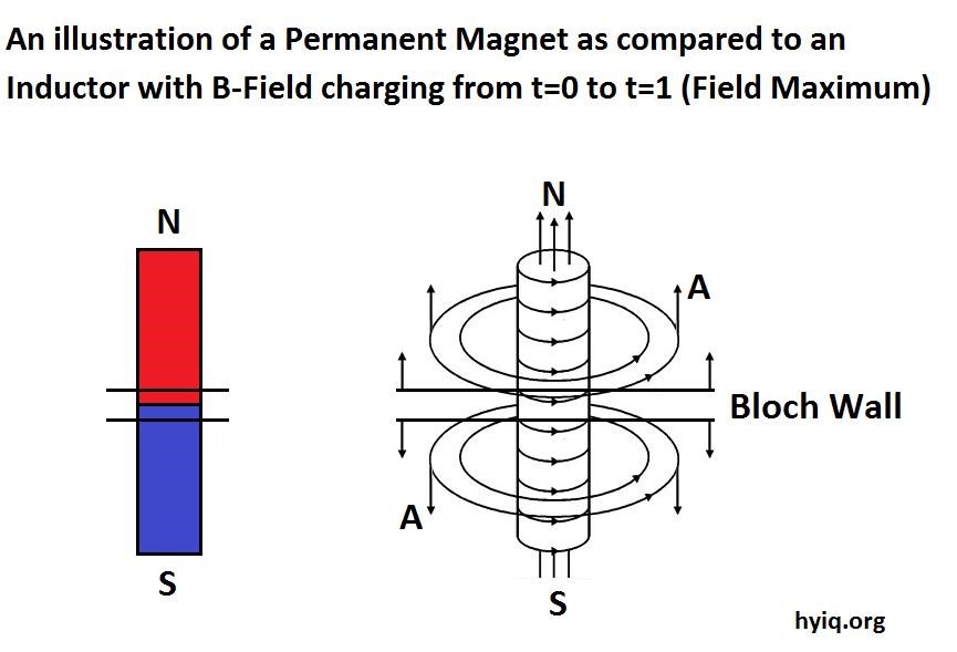
Fig. 1 is a well-known figure of all, it is a LC tank coil consisting of a coil and a capacitor.

The fig.2 is a half wave antenna consisting of 2 times ¼ wave which makes us a total length of lamda divide by 2.


When you compare the two figures you can see very quickly that there is a very big difference both physical and technical between the two, I explain myself.

The 4 main parameters to compare are: directivity, polarization, impedance and frequency.

For the coil of Fig.1 a tank coil, when the coil is cut to a certain length, there is resonance at a certain frequency and the fact of winding increases its inductance. It is helped by a capacitor to more precisely reach the desired frequency. The radiation of a coil is at its maximum in its center ie inside the coil so its directivity is at its maximum when it is located on the top of another coil and not at the inside, in order to have a maximum magnetic exchange.
As an example in the case of the Don Smith generator L1 is on the top of L2 coil and not on the inside. The polarization of a tank coil is infinite resonance and is governed by the rule of the right hand RHR and its impedance is infinite at resonance.

Regarding our fig 2 the antenna is not rolled like a coil but straight, it will resonate at the cutoff frequency and its directivity is omnidirectional and the power transmitted. Moreover the end of the quarter wave should never be connected to any other electrical component otherwise we would have an mismatched antenna , instead of having an impedance of 73 ohms, as we should have, it will be a mismatch with a stationary wave ratio very high SWR and no power radiate. For an antenna of this type one can have a vertical or horizontal polarization, the polarization is determined by the polarization of the antenna of the transmitter, one must have the same polarisation to the receiver to receive a signal.

After having examined these concepts on the LC tank and the half-wave antenna, we can conclude that they do not have many related links except that of their frequencies. One can not compare a tank coil to an antenna, the point of attachment of a half-wave antenna is crucial and that is what makes its impedance. The voltage in an LC tank is provided in both ends giving it an infinite resonance impedance. In a half-wave antenna the top part is the radiator and the bottom part is the ground plane and they could not be join.

Only an analogy on the word transmitter and receiver may be appropriate. Don Smith used rather the concept reactant coil and réactor coil it is much more precise.

To be continued, I hope I did not discourage you too much

Jack


Attached Files

Order By: Standard | Newest | Votes
Chris posted this 08 May 2018

Jack, this is a fantastic Thread! Great resource!

Antenna's and Coils as you point, have quite different characteristics, however, follow the same basic principles. In Antenna's, Near Field and Far Field are phenomena that is supposed to define some Field Characteristics:


However, there is no real theory I have found on this in Inductors. Inductors Radiate, but the Field effects are only ever talked about in an Induction scenario, which could be equated to the Near Field effect, equal and opposite.

The Mr Preva Experiment does prove that there is at least Near Field and Fresnel Effects.

Jack, a great post, thumbs up an Favorited from me!

   Chris

  • Liked by
  • Zanzal
  • Jagau
Jagau posted this 08 May 2018

OK well as you can see in you image fresnel equation predict  Te and Tm this the first who predict that.

about near fear its apply only to inductor i think.

well my post was just my point of view it can be discussed anyway.

have  a nice day

Jack

  • Liked by
  • Chris
  • Zanzal
Chris posted this 09 May 2018

Hey Jack,

NF Fields are most commonly associated with Antenna's. It is an interesting area to study.


Below, audio starts at: 1:43


All very interesting videos.

   Chris

Jagau posted this 09 May 2018

Yes indeed very interesting video to study.

I'm staying with the idea that it was magnetic near field of a coil you told me about RF near field

I'm sorry I was not talking about the same thing,

indeed radio frequency near field is different from the magnetic near field near the coil, I'm sorry.

Jack

  • Liked by
  • Chris
Chris posted this 09 May 2018

Hey Jack,

Apologies, I agree with your post. I strayed a little off topic.

   Chris


Chris posted this 09 May 2018

Hi Jack,

I know you already know this, but for all readers I would like to continue your Antenna concept.

An Antenna, can couple in the Near Field, a Current can be induced as we would conventionally see:


These theories, Near, Freznel and Far Fields are important concepts and much of our Wireless Communications technologies are based on these theories.


The above video is very important! A HUGE amount of very important information!

NOTE: The mention and statement of the Magnetic Field: 1 + 1 = 4


Also, this field of Electromagnetic Theory aligns very closely to Optics, especially what Tom Bearden was talking about, Phase Conjugate Mirror, PCM.

Its not to hard to see, the litraure does show ideas and concepts:

In LLC resonant converter, the integrated transformer with high leakage inductance is preferred to get high power density by eliminating the series resonant inductor. However, high leakage inductance results from stray magnetic field between primary winding and secondary winding, which brings near-field effect and severely impacts on near-by components. In this paper, the mechanism of near-field effect is discussed and the model of the integrated transformer applied in LLC converter is built. Furthermore, this paper takes the metal case of power supply for example to analyze the near-field phenomenon. Based on an 185W power supply, both simulation and experiment results are carried out. The near-field phenomena get well explanation.

IEEE - Analysis on near-field effect caused by stray magnetic field of integrated LLC transformer


Some interesting tech is starting to emerge!

   Chris

Chris posted this 09 May 2018

@All - How is this for coincidence:


   Chris

Zanzal posted this 09 May 2018

However, there is no real theory I have found on this in Inductors. Inductors Radiate, but the Field effects are only ever talked about in an Induction scenario, which could be equated to the Near Field effect, equal and opposite.

Great topic guys. I definitely need to know more about near and far field. Was reading something yesterday where the author claimed transformers work primary through the near field. While I am not sure I trust this author since he was very much against Tesla's claims that his wireless power transfer did not use Transverse EM waves, he did provide some good general info about near and far field:

http:// www.capturedlightning.com/frames/Non-Herzian_Waves.html

There is one way we can maybe test this. Assuming that the near field is blocked by a faraday cage we could surround the primary of a transformer with thick aluminum foil. If the power is being transferred as a result of the near field and if the near field is blocked by the foil then the secondary should be largely dead. Personally, I suspect the transformer will still work fine, but then if that turns out to be true, how do I know I really blocked the near field. Thoughts?

  • Liked by
  • Chris
  • Jagau
Chris posted this 09 May 2018

Hey Zanzal,

I still have a lot to learn in this area. I find this very interesting.

Assuming that the near field is blocked by a faraday cage we could surround the primary of a transformer with thick aluminum foil. If the power is being transferred as a result of the near field and if the near field is blocked by the foil then the secondary should be largely dead.

Initially I thought this also. I may be wrong, but I believe the Near Field is unshieldable:


To reference, Floyd Sweet said the same thing:

Of all the known fields - electric, magnetic, gravitational and motional E-field, the only ones incapable of being shielded are the induced motional E-field and the gravitational field.


Note the stated fact about Energy being the the Square of the Field.


The underlying principal (forget Millikan’s experiment) has been derived in that magnetic effects vary on the square of the current.

Floyd "Sparky" Sweet - The Space-Flux Coupled Alternator


The field energy is proportional to the square of the amplitude of the total electromagnetic field. As a result, the simple addition of the energy fields of the total field can be many times the energy of the initial fields separately. This property of the electromagnetic field is non-additivity of the energy field

Andrey Melnichenko - Transgeneratsiya electromagnetic field energy


I found this very interesting also:


So all the energy is stored in the Field, and this storage phase is around the Quarter Wavelength! This is a fantastic piece of information! Why, because it gives insight to the already known Quarter Wavelength requirement that we know of.

   Chris

  • Liked by
  • Jagau
Jagau posted this 09 May 2018

Hey Zantal excellent comment.

Nicholson should have read Maxell's book to understand what Tesla was saying. Moreover, Maxwell's ideas on the action of remote charges were poorly received in the scientific world at that time, he had to back down to retreat on what he had discovered so as not to displease.

In the paragraph  ''charge and field'' it's simply bad knowledge, I just do not agree with what Nicholson wrote. Who is he, have you ever heard of him?

Dr. Nicolas Tesla with more than 700 patents to his credit did not only joke about writing books he acted and unfortunately those who get involved pay the price.

Jack

  • Liked by
  • Zanzal
  • Chris
Zanzal posted this 09 May 2018

One can not compare a tank coil to an antenna, the point of attachment of a half-wave antenna is crucial and that is what makes its impedance. The voltage in an LC tank is provided in both ends giving it an infinite resonance impedance. In a half-wave antenna the top part is the radiator and the bottom part is the ground plane and they could not be join.

Only an analogy on the word transmitter and receiver may be appropriate. Don Smith used rather the concept reactant coil and réactor coil it is much more precise.

To be continued, I hope I did not discourage you too much

Jack

Hey Jack,

I'm trying to dig up information on this this subject as well. Have you read this:

http://amasci.com/tesla/tesceive.html

Its full of very interesting ideas.

One thing to consider too is if Don Smith's work is related to Tesla some have claimed that Tesla was transmitting power though the ground rather than the air or perhaps more precisely he was inducing AC to flow between two points on earth by using the earth / ionosphere as capacitive components in his circuit... Whether these claims are true I'm not entirely sure, but I'm trying to understand the concepts that would be involved.

Regarding your comment about the tank circuit/antenna, your antenna may seem very different especially since it has its own uses, but is it not capacitively coupled to anything, is it not just an inductor with physical properties (geometry) that make it useful for broadcasting em waves? Each has its own purpose and its own uses, but are they really all that different? I agree its really hard to compare the two side by side. But, if we consider the antenna as an inductor/resistor capactively coupled to the earth/ionosphere capactor though suddenly they don't look so different.

  • Liked by
  • Chris
Jagau posted this 09 May 2018

Excuse me that Shock me to read that about Tesla,  I would not write that .

jack

  • Liked by
  • Zanzal
  • Chris
Zanzal posted this 09 May 2018

Excuse me that Shock me to read that about Tesla,  I would not write that .

jack

No worries Jack, I don't get too invested in peoples opinions nor am I a member of any personality cults. Nor am I a member of the thought police union. That site I linked too is from William Beaty and it describes Beaty's theories. 

The idea that the ionosphere is one capacitor plate and the earth another is not my idea and I don't think it originated with Beaty either. But if these things are true than the earth and sky form a capacitive component and according to circuit theory any high energy wave travelling into the earth side of the capacitor must induce a reaction in sky side of the capacitor. Or in other words they form a completed circuit so my summary that you found somewhat shocking is really just an extrapolation of someone else's ideas. No one will ever be able to prove the modern scientific concept behind Tesla's 19th Century claims without first inventing a time machine.. It will always be one person's speculation.

  • Liked by
  • Jagau
  • Chris
Jagau posted this 09 May 2018

Hey Zantal

If we have a transmitter of 1000 watts (1KW) which makes a lot of power at 1 mile distance the siganl RF (radio frequency) received will be 0.1375 volts per meter which makes us a signal received  -12 db otherwise not even 1 volt.
We only have to imagine if the transmitter operates only a few watts.

What I mean, you can not use the RF signal to transform it into power, you have to amplify it and it is the precise components of the receiver that make it. There is not much to do with the RF if not only to communicate. If you approach either a metal object or another coil near the antenna you completely unbalance its impedance and the Tx no longer transmits (SWR)

On the other hand, a LC tank with a coil nearby, whether inside or outside, the impedance of the LC does not change as soon as we reach the resonance z = infinite, from which we can transfer the energy of point to another and use it in power. As in an ordinary transformer.

Jack

  • Liked by
  • Zanzal
  • Chris
Zanzal posted this 09 May 2018

What I mean, you can not use the RF signal to transform it into power, you have to amplify it and it is the precise components of the receiver that make it.

Consider reading what Beaty wrote on this, or not, its your choice to learn what you think is worth knowing... Good luck my friend, I don't want to derail your thread so I will bow out for a bit.

  • Liked by
  • Chris
Jagau posted this 10 May 2018

To visualize the effects when you touch an antenna with your finger or with different objects
At 1.26 minutes, the capacitance and frequency of resonance changes. Spectrum Analyzer allows us to see these changes in real time.


It should be remembered that the impedance of the antenna is well mathed at 50 ohms with a coaxial cable connected to the device. Maybe it can help to better understand things to avoid near an antenna. In fig 2 this is the kind of antenna that I had in mind when I explain a half wave dipole to avoid further confusion.

Jack

  • Liked by
  • Chris
Chris posted this 10 May 2018

Hey Jack,

A good video demonstration!

It is interesting, as the C or L changes so does the resonant frequency, this we would expect to see in both LC and also an Antenna.

The Distributed Capacitance of the Antenna is tiny, and as shown in the video, it easily changed.


We know already, any wave reluctance creates problems for Antenna's. Its amazing how little  it takes. I enjoy Antenna Theory, still have lots to learn however.

   Chris

Jagau posted this 10 May 2018

Very interesting video to visualize a mismatch.

What it actually explains is what happens in a cable when the cable has different inpedance and this is associated with Time Domain Recflectometry (TDR).

As you know, I often have to check the impedances of the coaxial transmission lines and I have a nice little device for that.
Aim uhf. Their website is very explicit: google aimuh and the spec of the device are there.

What interests us is the TDR goes to page 68 of the attached book and you will find an explanation of the video you just came to put on the site.

I do not want to advertise but this little device saved me a lot of time on VHF repeater site.
It detects a break in the cable and also tells you the distance from the source.

I quote them:

Note the one-way cable loss is numerically equal to one-half of the return loss. The return loss is the loss of the signal experiences in two passes, down and back along an open cable.

Agilent has a good service note on the TDR look at figure 7a you'll recognize her.

Jack

Jack

Attached Files

  • Liked by
  • Chris
Chris posted this 10 May 2018

Thank you Jack!

Another great post, I have learned a bit more again today!

Reading page 68 now. I very much enjoy EM Waves and how they work in a medium, or mediums.

   Chris

Chris posted this 14 May 2018

For those that would like to learn a little more about the Radiation stored in the Near Field, this article is very good:


Antenna Near Field Radiation


   Chris

onepower posted this 14 May 2018

It's strange that there are libraries filled with textbooks on antenna theory. All those textbooks filled with complex math and equations simply to describe... a wire with a standing wave in it which radiates energy. It would seem to be a gross overstatement of the obvious in my opinion. 

All that theory and math and yet they still seem to have no real understanding how it works. How electric and magnetic fields can travel through an apparently empty space. 

  • Liked by
  • Chris
Jagau posted this 14 May 2018

Thank you Chris for sending me this link.


Very interesting to read with a lot of material to explain well.Not easy to popularize the technique.

At first glance we can understand the complexity of near field measurements and their mini-double with impedance matching 2 x 18K resistors very ingenious. I do not understand their impedance matching with 2 resistance d 18k knowing that the monopole antenna is 36 ohms? to study!

Far field is more easy.I will continue to read the other articles of this link very interesting also

thank you for sharing.


Jack

  • Liked by
  • Chris
Chris posted this 14 May 2018

@Onepower - I agree. Many thousands of very smart people all attempting to contribute to a field that is still to this day partly misunderstood! I read an article: "Electromagnetic Wave Propagation in the Near Field of a Quarter-Wave Monopole with a Finite Ground Plane", which brings "De Broglie Wavelength Proper-Time Demonstration" into the theory.

Very interesting, considering De Broglie Waves are known to be many times the speed of light.


Many argue this point, but who really knows.

Light is bent by Gravity, surely the medium light travels is the same Gravity propagates, viscosity of the medium may vary, but Light is subdued by Gravity we know to be true! Light Speed is a constant for Light, not for Gravity, Black holes absorb Light, a -Negative Mass where Light can not escape, a fundamental flaw, the postulate that is mostly true... most of the time, time is another problem in itself.

A very large over complication to what should be a simple field, but do I have all the answers, not yet. Using basic Antenna Theory does help make machines work, but I do not understand or have a complete theory.


@Jack - Notice the terms used: "A Vector Potential" is a common term in the above link in this post. One we have focused on also. I recently covered: The Field Structure of Nature


Yes, I agree, I also need to study more.

   Chris

We're Light Years Ahead!
Members Online:
What is a Scalar:

In physics, scalars are physical quantities that are unaffected by changes to a vector space basis. Scalars are often accompanied by units of measurement, as in "10 cm". Examples of scalar quantities are mass, distance, charge, volume, time, speed, and the magnitude of physical vectors in general.

You need to forget the Non-Sense that some spout with out knowing the actual Definition of the word Scalar! Some people talk absolute Bull Sh*t!

The pressure P in the formula P = pgh, pgh is a scalar that tells you the amount of this squashing force per unit area in a fluid.

A Scalar, having both direction and magnitude, can be anything! The Magnetic Field, a Charge moving, yet some Numb Nuts think it means Magic Science!

Message from God:

Hello my children. This is Yahweh, the one true Lord. You have found creation's secret. Now share it peacefully with the world.

Ref: Message from God written inside the Human Genome

God be in my head, and in my thinking.

God be in my eyes, and in my looking.

God be in my mouth, and in my speaking.

Oh, God be in my heart, and in my understanding.

Your Support:

More than anything else, your contributions to this forum are most important! We are trying to actively get all visitors involved, but we do only have a few main contributors, which are very much appreciated! If you would like to see more pages with more detailed experiments and answers, perhaps a contribution of another type maybe possible:

PayPal De-Platformed me!

They REFUSE to tell me why!

We now use Wise!

Donate
Use E-Mail: Chris at aboveunity.com

The content I am sharing is not only unique, but is changing the world as we know it! Please Support Us!

Thank You So Much!

Weeks High Earners:
The great Nikola Tesla:

Ere many generations pass, our machinery will be driven by a power obtainable at any point of the universe. This idea is not novel. Men have been led to it long ago by instinct or reason. It has been expressed in many ways, and in many places, in the history of old and new. We find it in the delightful myth of Antheus, who drives power from the earth; we find it among the subtle speculations of one of your splendid mathematicians, and in many hints and statements of thinkers of the present time. Throughout space there is energy. Is this energy static or kinetic? If static, our hopes are in vain; if kinetic - and this we know it is for certain - then it is a mere question of time when men will succeed in attaching their machinery to the very wheelwork of nature.

Experiments With Alternate Currents Of High Potential And High Frequency (February 1892).

Close