How to Measure Power - AC

  • Topic Is Sticky
  • 990 Views
  • Last Post 13 November 2020
Chris posted this 25 June 2017

This topic is to help measure AC Sinusoidal Power and be as accurate as possible.

First, this only works with Sinusoidal Wave forms, irregular or square wave forms are not measured this way, and if done so will not yield accurate results.

Measure Current using a Current Shunt, sometimes known as a Current Viewing Resistor (CVR) or more commonly known as a Current Sensing Resistor (CSR). This turns Current into a Voltage Wave Form, something we can see on the oscilloscope. A simple Circuit follows, where we measure the Current (I) that is in the Circuit, the Lamp will carry the same current we sense across the Resistor. This is Kirchhoff's Current Law, where all nodes in a Circuit must carry the same Current.

The value of the Current is determined by Ohms Law, where the Voltage across R1, this is the Voltage Drop, is V/R = I, Voltage / Resistance = Current.


Example:

  • We measure a 0.1 Volt Drop across the Resistor R1.
  • Total input Voltage is 10 Volts.
  • The Resistance of R1 is 0.1 Ohms:

So, the Current in the Circuit is: 0.1 / 0.1 = 1 Ampere.

We have a Voltage Drop in our Resistor, and this is dissipated as Heat, so there is Power being used here, this can be calculated as: V2 / R = P so 0.12 / 0.1 = 0.1 Watts dissipated in the CSR

Thus, the Total Power in the load: 9.99 Watts

Steps:

  • Take Voltage Measurement, Use RMS Values from your Scope.
  • Take the Current Measurement, again use RMS Values from your Scope.
  • Measure the Phase Angle between the two Wave Forms. The following Video is a good resource:

Note: Some say you should use Mean Values. It is up to you, and may be worth comparing the two values. The RMS should work out to be the mean anyway, as this is the entire point of RMS, Root Mean Square, the RMS difference from Peak Values is the Mean.


Make sure you check your scope probes, make sure you account for the magnification, either 1x 10x or more.

The equation for calculating AC Sinusoidal Power is: V x I x Cos(Theta) where Theta is the Phase angle in Radians.

As a quick and easy resource, I have added an AC Power Calculator to my website: AC or Sinusoidal Power Calculator

By using this calculator, it makes for a quick easy painless measurement.

Note: My calculator takes Degrees and not Radians. Also, try to use Precision Sensing Resistors, they are very cheap, and worth the investment!

Hope this helps!

   Chris

  • Liked by
  • Zanzal
  • Vasile
Order By: Standard | Newest | Votes
Chris posted this 25 June 2017

Hi Vasile - Yes, A Resistor in the Circuit will introduce extra Impedance, this is an extra Load, if you like, and must be accounted for.

Rule of Thumb: Use a low valued Resistor, to reduce the extra Circuit Impedance as much as possible, but not too low or it will be very hard to get accurate measurements. I like a 0.1 Ohm Precision Resistor. The reason, If I set my scope probe to 10x, all I need do is take my Current reading as 1 x on the scope.

For example: 1 Volt across a 1 Ohm Resistor will see 1 Amp in the Circuit - Ohms Law. But a 0.1 Ohm Resistor with a 0.99 Ohm Load, with 1 Volt across the Load's is 1/10th the value  So, we know, because Ohms Law is your Friend, that 1 Amp is flowing in the Circuit, because 1 Volt across 1 Ohm is 1 Amp, but we are only measuring at a 10th of the Resistance in the Circuit. A Diagram to help:

XMM1 measures the total Voltage Drop at 1 Volt, with a small rounding error. This is correct, it is measuring the Amperage at 1 Amp as the Voltage across 1 Ohm is 1 Amp. However, XMM2, the 0.1 Ohm Current Sensing Resistor (CSR) is only 1/10th the total resistance, and this is correctly measuring 100mv because the Resistance is 1/10th the total value.

So, you can see, using a 0.1 Ohm Precision Resistor and setting the Scope to 10x, gives me the correct value of current, it does the Math for me and all I do is read off the screen.

Note: This is a DC Example, and AC is the topic. I recommend using a scope to do the measuring, so you can see the wave forms. You can use a Digital Multi Meter, but the problem is, if you do not have a Sinusoidal Wave Form then your measurements may be in vein.

Some years ago, I built what I call Measurement Blocks, cheap and easy. Although these Through Hole Current Resistors are not labelled "Precision" they are remarkably accurate! ±1%


I also have these:

These are Precision, and I use them for an extra check on my small tolerance stuff.

This makes life easy, The only thing is making sure there is no Ground Loop, which is easy with some practice.

I hope this helps!

   Chris

  • Liked by
  • Vasile
  • Kritischer
Chris posted this 27 June 2017

Hi Vasile - Please keep in mind that Hall Effect Current Probes can have their own set of problems. They are not always a more accurate way to measure Current.

Its worth noting that some I have used do have issues like Phase Angle Delays which can mean a big difference in Accuracy. Some are just not accurate at all.

Also, some are. So it is worth knowing both methods to verity the result of the other.

   Chris

  • Liked by
  • Vasile
  • Kritischer
Chris posted this 23 August 2017

I have been taking a look at this discussion as I think it is very important and noticed an error.Isn't R2 suposed to be 0.9 Ohm and not 0.99Ohm as you have writen?so as to sum up with R1 to 1Ohm?

I am glad you are paying attention Vasile.

Yes, exactly! 0.9 and 0.99 are not the same number! This introduces a 0.99 - 0.1 = 0.89 of an error. The "Rounding Error" I indicated at.

   Chris

  • Liked by
  • Vasile
  • Kritischer
Vidura posted this 13 November 2020

Hi All, When I started learning about the concept of reactive power it was a bit difficult to grasp, thanks to Chris' patient explanations I understood. Now I found this text, explained in a simple way, and thought it could be helpful for those learning the basics:

"What's the physical meaning of reactive power? In electric circuits, some common misconceptions can make Reactive Power quite confusing. Before proceeding, first we have to fix our foundational ideas. For example:

With AC, the energy flows back and forth? Wrong. Only the electric charges flow back and forth, while the energy ideally goes in a single direction. (It’s a bit like sound waves versus wind. The air wiggles back and forth, while the sound waves move in a single direction. In circuits, the charges wiggle back and forth, while the energy goes in a single direction.)

Electricity is a form of energy? Wrong, the coulombs of electricity are not joules of energy. Electricity and energy are two entirely different things; two separate kinds of flow, and an ampere is not a watt. Important: the amperes are a very slow flow, while the watts are a light-speed flow. (Again, this is analogous to slow wind, versus fast sound waves, both in the same bit of atmosphere. Amps are the wind, watts are the propagating sound: waves versus medium.)

Electricity travels at the speed of light inside wires? Wrong. It's only the energy which travels at nearly the speed of light. At the same time, the electricity circulates quite slowly. Or with AC, the electricity wiggles back and forth. Electricity is the medium, and the Electrical Energy is the waves.

The energy comes out of the generator, flows through the light bulb filament, then returns to the generator? Nope, only the electricity does that; it flows in a closed circle without loss. Energy behaves very differently. Instead the energy comes out of the generator, travels rapidly along both halves of the circuit, then it gets absorbed by the light bulb filament. In the cord for a lamp or a blender, the energy zooms along both wires at the same time. In a 3-phase system the energy zips along all three wires in the same direction. Energy goes one-way, from source to load, while electricity travels in a complete loop and returns to its starting point. (It’s analogous to closed-loop hydraulics. The oil flows slowly in a circle, while the “horsepower” moves instantly through the system, zooming out of the pump, and making the distant hydraulic cylinders move instantly, without visible delay, even though the liquid moves slow.)

OK, then what is Reactive Power?

It’s simple. Reactive Power is when the ENERGY vibrates back and forth! Ha!

See why this can get confusing?

Usually the electricity wiggles, while the energy goes smoothly forward. If we believed that “electricity” was one single thing, then we’re screwed. We’ll never be able to understand. Or instead, if we wrongly imagine that electricity was a form of energy, or that the energy is always "alternating" in an AC system, then our concepts are completely distorted! In that case we'll never be able to grasp the concept of reactive power, or even truly understand basic electric circuits.

So, first we must attain a clear understanding of the two kinds of flows: the charge versus the energy, and to also understand how watts move along, versus the amperes.

The amps go sloooowly in a complete circle, moving like a drive-belt, or like a very long flywheel, while at the same time, the watts travel rapidly; traveling down both wires in the same direction, going at nearly light-speed. (Again, look at your oldschool AC desk lamp, and visualize that the energy is flowing along both wires, going from the wall-outlet to the light bulb, where it is absorbed by the hot filament.)

Rather than the Alternating Amperes, instead what happens when the energy starts going back and forth? This just means that electrical energy is "sloshing" to and fro between the AC generator and the distant loads. Normally this wave-energy flows smoothly in just one direction, going from the Utility Company to your washing machine. But instead, if the energy bounces back and forth between the separate ends of the power-grid, that just means you're not using up that energy. Instead you’re sending it all back to the generator.

This “energy-sloshing effect” is measured in watts of Reactive Power. If the energy all reflects back to the power company, that’s pure 100% reactive power. But if instead your light bulbs are using up electric energy, with none bouncing back, that’s purely “Real Power.”

Capacitors can set up this "energy sloshing" situation, if used as the load.

Capacitors ideally draw only Reactive Power. When connected to a dynamo, they don't constantly absorb electrical energy, as with heaters and motors. Instead capacitors charge up …and then discharge again. They bounce all the energy back to the source. (Coils as loads will ideally do the same thing: filling up and then emptying, reflecting the energy back to the distant AC dynamo.) If we plug our capacitor into a wall-outlet, then ideally all the electrical energy which is going into the capacitor ...goes right back out again, and returns to the distant AC source. Then repeat! Charge up your capacitor, then discharge it back into the distant dynamos. (Actually this happens twice per complete cycle of AC, where the energy sloshes at 120Hz rather than 60Hz. For energy transfer, the polarity doesn’t matter, and your load-capacitor stores some energy on the positive AC cycle, and again on the negative. Twice per cycle.)

An ideal coil does almost the same thing. Connect it to the AC source, and first it becomes “charged” with a large current and magnetic field, then it “discharges” again, where the field collapses and the energy gets sent back to the dynamo. Then it does it all again, on the opposite AC half-cycle.

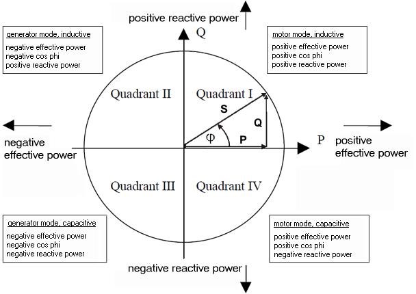
On the other hand, "Real Power” means that energy goes one-way only, from source to load. We have to pay someone for real power. "Reactive Power” means that energy goes back and forth only, with none being absorbed. "Complex Power" is just the sum of the two effects, with some energy being genuinely absorbed by the load, but part of it being bounced back to the dynamos again.

Pure resistors draw Real Power only: the one-way energy-flow. Pure capacitors (and coils) draw Reactive Power only, where the energy-waves all “slosh back” to the distant dynamo.

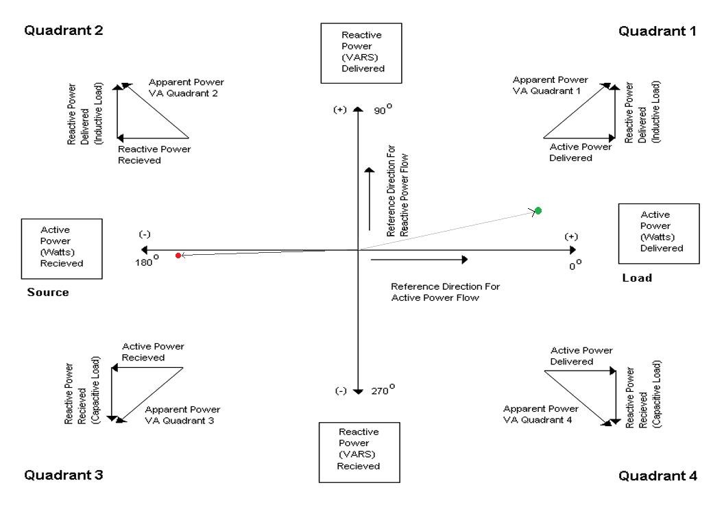
OK, where do these effects appear in the AC mathematics? If we start graph-plotting the sine-waves of voltage and current, jthen ust where do we see this “energy-sloshing” effect? The answer is actually straightforward.

In a lamp-cord or other 2-wire transmission line, if the voltage and current are in synch (zero phase difference,) then the electrical energy is traveling in a single direction, call it right-to-left. (Imagine powering a flashlight bulb with a battery, but then reverse the battery terminals. The energy still flows in the same direction, going to the bulb!)

Now instead if the current is 180deg out of phase with the voltage, then still the energy is traveling in a single direction, but backwards. It flows smoothly left-to-right.

These changes between 0deg and 180deg are reversing the average long-term direction of energy-flow.

What would happen if the phase-delay between volts and amps wasn’t zero, and also wasn’t 180deg? Yep, you guessed it. That’s when the energy starts wiggling back and forth. With a small phase-shift between the voltage and the current, then for each AC half-cycle, the direction of watts reverses twice, first forwards, then back, then repeat.

And finally, if the phase-delay is exactly 90deg, or exactly -90deg (270deg,) that means we have “purely sloshing” with no net energy flow at all. At those values of phase-delay, every bit of the energy that traveled right-to-left, is sent back again, left-to-right. These special angles are seen whenever we use ideal capacitors and ideal inductors as our load. Neither of these components use any net energy. But they sure do “slosh” energy around, first a “charge” then followed by a “discharge.” Coils and capacitors …it’s almost as if they were the same component! Capacitors store energy as e-fields, inductors store energy as b-fields. In capacitors, the stored energy is related to the voltage, in the coil its related to the current. Capacitors cause a 90deg phase lead, the coils a 90deg phase lag. (Capacitors, they’re just coils which have somehow been turned inside-out!)

It’s all simple, really. Once you can see it in your mind. The serious complexity appears when both inductors and capacitors are present, or we start adding resistors into the mix, all with phase-lags which aren’t exactly -90deg, 180deg, etc. (“Complexity.” Heh.)

And finally, notice that there’s nothing imaginary about any of this. Reactive power has nothing to do with imaginary flows, and everything to do with “energy-sloshing” flows. [I think “imaginary numbers” was a terrible name for them. They should have been called “sideways numbers” or something less misleading. “Contrary numbers,” so that a capacitor would be drawing “contrary watts” from the AC grid, instead of “imaginary” watts!]" By William Beatty

  • Liked by
  • Chris
thosewhocandothosewhocantteach posted this 13 November 2020

https://www.youtube.com/user/mathtutordvd/playlists

https://www.youtube.com/c/MichelvanBiezen/playlists

https://www.youtube.com/user/katkimshow/playlists

https://www.youtube.com/user/sambenyaakov/videos

Happy learning!

  • Liked by
  • Chris
Chris posted this 13 November 2020

Great Post Vidura!

Thank You!

We have seen the Argand Diagram before:


Well, this diagram is extremely detailed and has a lot in it that can be gleamed. Reactive power is seen when the Voltage Current have a Phase angle difference, here is an example:


Voltage sits on the X Axis, 0 and 180 consecutively, as Voltage can only ever be Positive or Negative! But at any Magnitude! Current can be at any Angle from Voltage, and Magnitude, thus we need to have a more detailed visualisation for Current. 

You can see indicators, 0, 90, 180, 270 and back to 0 or some may like to hear 360, in other words a full revolution:


This Counter Clockwise Rotation shows the States at which Voltage and Current can be related to Each other. Positive Voltage and where we see the Green Dot, we get Current that is approximately 25 Degrees out of phase.

Example: Power P = V x I x cos(theta) so what's Theta? Its the Phase Angle:


Theta has two cases: θ and Θ

The above Symbol, I believe is supposed to be Theta, but drawn differently, seen correctly in the second image, I am not exactly sure on that first image!

The following video is one of my all time favorites.


Science will tell you, Power can only do Work, if the Voltage and Current are in Phase. When Voltage and Current are Out of Phase, then no Work can be done, thus this Power is Reactive and thus termed Pin Pong Power in the above Video.

So, Vidura's analogy is correct and does describe Reactive Power very well! Thank You Vidura for sharing!

Best Wishes,

   Chris

We're Light Years Ahead!
Members Online:

No one online at the moment


What is a Scalar:

In physics, scalars are physical quantities that are unaffected by changes to a vector space basis. Scalars are often accompanied by units of measurement, as in "10 cm". Examples of scalar quantities are mass, distance, charge, volume, time, speed, and the magnitude of physical vectors in general.

You need to forget the Non-Sense that some spout with out knowing the actual Definition of the word Scalar! Some people talk absolute Bull Sh*t!

The pressure P in the formula P = pgh, pgh is a scalar that tells you the amount of this squashing force per unit area in a fluid.

A Scalar, having both direction and magnitude, can be anything! The Magnetic Field, a Charge moving, yet some Numb Nuts think it means Magic Science!

Message from God:

Hello my children. This is Yahweh, the one true Lord. You have found creation's secret. Now share it peacefully with the world.

Ref: Message from God written inside the Human Genome

God be in my head, and in my thinking.

God be in my eyes, and in my looking.

God be in my mouth, and in my speaking.

Oh, God be in my heart, and in my understanding.

Your Support:

More than anything else, your contributions to this forum are most important! We are trying to actively get all visitors involved, but we do only have a few main contributors, which are very much appreciated! If you would like to see more pages with more detailed experiments and answers, perhaps a contribution of another type maybe possible:

PayPal De-Platformed me!

They REFUSE to tell me why!

We now use Wise!

Donate
Use E-Mail: Chris at aboveunity.com

The content I am sharing is not only unique, but is changing the world as we know it! Please Support Us!

Thank You So Much!

Weeks High Earners:
The great Nikola Tesla:

Ere many generations pass, our machinery will be driven by a power obtainable at any point of the universe. This idea is not novel. Men have been led to it long ago by instinct or reason. It has been expressed in many ways, and in many places, in the history of old and new. We find it in the delightful myth of Antheus, who drives power from the earth; we find it among the subtle speculations of one of your splendid mathematicians, and in many hints and statements of thinkers of the present time. Throughout space there is energy. Is this energy static or kinetic? If static, our hopes are in vain; if kinetic - and this we know it is for certain - then it is a mere question of time when men will succeed in attaching their machinery to the very wheelwork of nature.

Experiments With Alternate Currents Of High Potential And High Frequency (February 1892).

Close