Floyd Sweet VTA - Magnet Conditioning Confusion

  • Topic Is Sticky
  • Topic Is Locked
  • 3.3K Views
  • Last Post 01 August 2020
Vidura posted this 24 February 2020

Hello Friends,

In response to the excellent videos I felt to start a new thread on this topic. This is the first time I saw an image of the actual VTA device, at least it seems to be genuine. It called my attention that all the lab tools are labeled, maybe he used to work this way, a bit  strange. 

Ok, the reason to post in tier2 category is mainly for not distract the newcomers for the moment , and discuss with most experimented members first. Maybe we  will move it to public access later. I had some short communication with yoelmicro a time ago regarding this device, but as I never saw an image I could not understand much. now I became really inspired , form watching the image and the simple experiments performed by Chris. 

Order By: Standard | Newest | Votes
Vidura posted this 24 February 2020

One thing Yo told me that in his opinion the magnets where not magnetised in sense on the thickness ,but in sense of the length, or width, otherwise there will be no induction, as shown in Chris experiment. After thinking about the claimed working principle, excitation of movement of the magnetic flux, causing EM induction in the output coil. In my opinion the so called magnetic field or flux is not a property of the magnet, but of the environment, i'll call it aether like the ancients. there exists different models to imagine this magnetism, the most approaching might be a kind of vortices movement of the aether, but this is not of much concern for the moment.

Regarding the conditioning for the moment I will abstain to vote for or against it, In the sense of weakening the magnet it dont make much sense to me, but I also heard another explanation, related the phase conjugated optics, that the permanent magnet has the spin of the atoms aligned, but not In phase, and that the process was indented for phasing the magnetic flux , which would make it uniform in strength and direction over the area. I have no knowledge in PCO neather in material conditioning, so for the moment I will let this beside, and when I have some time perform a couple of the "simple experiments. 

Here is the Idea that occurred to me, how this could work in terms of electromagnetic induction: 

Imagin this sketch as a cut thru viewed from the front.


Vidura posted this 24 February 2020

Hey Friends,
There is a lot of information that I did not know, I certainly will go thru it . Regarding the razor blade I did not make experience with this still. It will be difficult to find this size of magnets. It is likely that it will be at my next trip to Europe, like the metglass cores. But regarding Faraday's law of induction I have no doubt that it can work the way it is setup in the sketch. The direction of the magnetic fields is identical like in Chris experiment when the coil is in between the two magnets. @Chris If you feel that there is already a thread covering this, feel free to move it there. Regards Vidura

Jagau posted this 24 February 2020

Hello Vidura

I believe that it is a good idea to check that the magnetization is in the direction of the thickness that has not yet been tested.
Gabriel Kron who was Sweet's teacher explained that lamellar currents predominated in some cases, so the best way to know is to try it out by experimentation


Jagau

Vidura posted this 25 February 2020

Hey Chris, Of course, yo can change the title as you feel. Already I told that my intention is further investigation of other possibilities, bench testing for documentation of facts, and finally a working machine hopefully. The conditioning yes or not I will not pay attention for the moment, as I have planned to investigate first the underlying principles, like the moving magnetic flux, conditions necessary for getting an EMF, effect of lenz law, possible construction details, and so and to collect as much information as possible. By the way , the 8 shape coil do not solve the canceling of the induction in a homogeneous field, we will have still two conductors in each direction ,two in the middle. O am convinced the magnetic axis is thru the length or wide side , I see no manner to get it working with the axis thru the thickness. Regards Vidura

Chris posted this 25 February 2020

My Friends,

What I am trying to do is point out the simplicity's, point out whats required for the Charge in the Wire to be forced down the wire, the very basic minimum requirements and I think, what I have been sharing for years now shows the basics.

Partnered Output Coils shows the basics, we know how to get the voltage up, we know from quotes Floyd Sweet looked at this also:


Current is deemed as a quantity or number of charged particles moving from P1 to P2 in time t, or as the charge transferred in one second by a current of one ampere. The coulomb is the charge on 6.24 x 1018 electrons. Electric fields are due to the presence of charges. Magnetic field effects are due to the motion of charges. Current is the net rate of flow of positive charges. This is a scalar quantity. In the specific case of positive charges moving to the right and negative charges to the left, the effect of both actions is positive charge moving to the right. Current to the right is:

I = da+/dt + da-/da

Negative electrons flowing to the left contribute to the current flowing to the right. 

Voltage: The energy transfer capability of flow of electric charge is determined by the potential
difference or voltage through which the charge moves. A charge of 1 coulomb receives or delivers an energy of one joule or watt-second in moving through a voltage of 1 volt or:

V = dw/da

Ref: The Space-Flux Coupled Alternator


The feedback loop: Previously mentioned, you will more clearly see how the loop functions at the time you see the physical construction of the stationary armature of stator assembly. The underlying principal (forget Millikan’s experiment) has been derived in that magnetic effects vary on the square of the current. As the load on the machine increases, the volt-ampere product increases. The rate of flow of charges increases. Quantum mechanics state not all electrons in copper are free to carry charges. Then it’s time to set the wheels in motion to free them from binding magnetic forces. Once this is done, conductivity will improve and resistance decrease as we are dealing only with electrons. Copper will not change to another metal as atoms which are mostly empty space would have many electrons to spare anyway.

Ref: The Space-Flux Coupled Alternator


We now have, when the current and voltage windings are excited, another set of fields, virtually in quadrature with the alternating fields initiated by the load current flowing in the power phase coils. The current and voltage initiating fields are in such a direction to either accelerate or decelerate the rate of flow of charges depending on the applied polarity and voltage amplitudes.

As polarity may be maintained constant, that polarity of acceleration should be chosen so charges move at faster rates, lowering copper duty factor, at the same time opening the gates wider so more coherent field entities may enter for the conversion process.

It’s obvious, we have a self-regulation machine whose inherent conservation to the nth degree.

Ref: Letter to Mark from Sparky


Function of the voltage feedback: To provide a means of capturing more incoherent quanta to complement the existing integrated flux densities and BHC or energy product. More feedback in the form of volt-ampere product at a cos of = 1 or unity of watts in the form of D.C. potential. This is obtained by potential transformers sensing the output terminal volts as this is virtually constant. The transformers are needed for isolation and for providing a much lower voltage that is rectified by a 3 phase full wave bridge and applied to a special potential winding in the stator assembly. How both the current and potential windings are assembled into the stator winding assembly is proprietary. The current and potential windings require relatively little power, and are applied in such a manner that rate of flow of moving charges may be accelerated beyond 1 ampere = 6.24 x 10¹⁸ electrons per second. Thus the duty factor of the copper changes.

I2R Losses diminish and more charges drawn from the now coherent space field flow at a faster rate as current to the load. This means as more current is required by varying loads more feedback magnetomotive forces free more electrons from binding forces complimented by potential magnetic forces of the orientated, coherent space field. Thus a conductor that formerly had a temperature rise above ambient labelled as a factor of 10 would now operate at a temperature of 1.0. Thus the same gauge wire would carry 10 times more current at the same temperature.

Ref: The Space-Flux Coupled Alternator


We now have, when the current and voltage windings are excited, another set of fields virtually in quadrature with the fields (alternating) initiated by the load current flowing in the power phase coils. The current and voltage initiating fields are in such a direction to either accelerate or decelerate the rate of flow of charges depending on the applied polarity and voltage amplitude.

As polarity may be maintained constant , that polarity of acceleration should be chosen so charges move at faster rates, lowering copper duty factor, and at the same time opening the gates wider so more coherent field entities may enter for the conversion process. It’s obvious; we have a self-regulating machine whose inherent magnetic proper ties will provide energy conversion conservation to the Nth degree.

Ref: Space-Quanta Modulator - Clean-Propulsion Power Now!


If the directions of the two signals are such that opposite H-fields cancel and E-fields add, an apparently steady E-field will be created. The energy density of the fields remain as calculated above, but the value of the E-field will double from E/2 to E.

Ref: NOTHING IS SOMETHING


Reading Floyd Sweets documentation, and realising what a Charged Particle does in a Magnetic Field due to The Lorentz Force, is a very straight forward perspective.


Its critical we think about this logically! Its critical we make educated and logical steps forward.

   Chris


Chris posted this 26 February 2020

My Friends,

At all reading, I urge all to follow simple rules of what I have shared with you already:


A very Simple question, why are the Coils configured the way they are? Zoom in and study the images carefully! Why are the Arrows significant?


Study very carefully! Other wise you will be wasting your time and money!

   Chris

Vidura posted this 27 February 2020

Thanks for posting this images, you are certainly correct that here can be learned a lot. No worries Friends, I will perform some benchwork and keep a low noise level meanwhile, in order to not disturb the concentration in the work with the POC.

Just one more thing, did anyone notice why this config would not generate an EMF?

Chris posted this 27 February 2020

Hey Vidura,

I am sorry, the Image is not clear enough for me to make a guess. What orientation are the Coils? What changes are you proposing to the Magnets?

I just don't have enough information.

What is required is:

Geometrically, one half of a Coil must see opposite change of Magnetic Flux to "Generate" an E.M.F.


If the Flux and Coil meets this requirement then an E.M.F will be "Generated". Now this does not mean a Current will sustained. One can have a Voltage and have very little current. I have explained here on this forum why this is.

If I can suggest, and as I always have, doing experiments on Magnets, costing Money, when we are not really sure on what is required, is a waste of Money. I have always suggested Simple Experiments that one can learn as much as possible first. We know we need a Voltage, we now know whats required for a sustained Current.

I suggest that all experiments are done first to see exactly how an EMF can be "Generated" before any damaging modifications are made to the Magnets. I believe this is very important! But again only a suggestion! I do speak from experience as you know.

   Chris

Chris posted this 27 February 2020

Hey Vidura,

In our past experiments, we have seen and covered in great detail the fact the Bucking Coils do not allow the Voltage to climb sufficently for a Machine to produce more Output than Input.

For this reason, we must "trick" the Coils to get the Voltage up.

An example of this is when we covered the Ruslans Flashlight without Batteries. I posted this:

On the Inductor we feed the signal of rectangles with a frequency of 1/50. Consider: 1820: 50 = 36.4 kHz pumping a rectangle through the junction (Pot) with 23-29 turns of wire 2.5 squares. I repeat, you need to make the voltage on this harmonic not 10-20 volts, but higher by an order of magnitude. Approximately up to 50-60 volts and get the same dancing effect at the output


Why not 10 - 20 Volts? Why 50 - 60 Volts?


This answer lays in the Coil Coonfiguration, remember the context was Tariel Kapanadze's Grenade Coil, the Tesla Coil:


Working out the level of Induction, we see almost 2 thirds of the Coil is Non inductive, Lets work it out:

Math:

2 Layers CCW.

0.5 Layers CW + 0.5 Layers CW + 0.25 Layers CW + 0.25 Layers CW.

So, Turn for Turn, we have 0.5 + 0.5 + 0.25 + 0.25 = 1.5

This means we have 2 - 1.5 = 0.5 Layers that are inductive, technically. In experiment, we see a slightly different story. 2 + 1.5 = 3.5 = 14.2857% which is not 0.25, but you see where I am going with this. Remember we are loosing a turn every layer also which I have not accounted for.

So whats 2 thirds of 220 Volts?

Answer: â€­72.6‬ Volts.

Or whats 14.2857% of 220 Volts =  31.42854Volts. One needs more because of the Close proximity of the Magnetic Nullification area.

So you see why we need to get the Voltage up in this situation, the Non Inductive Component because its not allowing a CHANGE in magnetic Field, does not Induce an E.M.F or a Voltage.

Remember: A Change in Magnetic Flux does not Pump Current, it is only related to Voltage.

Also, that's why some turns are directly on top of each other and some not. So we see an example of direct effort to get the Voltage Up! Getting the Voltage up is a very important part, something we have covered many times here on this forum. If one can get the Voltage up and have Bucking Coils, then the machine will pump copious amounts of Current as long as you have that Potential!

Another example is Delayed Conduction.

I am sure others here can point to 20 or thirty other places we have covered this particular topic.

Best wishes,

   Chris

YoElMiCrO posted this 27 February 2020

Hi everyone.

I join the project, back in 2016 I carried out many tests regarding the VTA.
I have to say that the one that motivated me was Chris, because since then
i followed his experiments on this subject and the greatest information on the net was disclosed by him.

Thanks in advance.
YoElMiCrO.


Vidura posted this 27 February 2020

hey Chris

analysing the device step by step,  I was looking first for the configurations which would generate EMF, the behaviour of currents, or under load will be the next step. you had the correct answer in your first response:

 Geometrically, one half of a Coil must see opposite change of Magnetic Flux to "Generate" an E.M.F.

As in my sketch the flux lines would move from the center in oposite directions, BUT the polarity of the field would be oposite on both halves of the coil,  so we have the same cancelling effect as described in the video about the law of induction.

I would conclude that the drive coils must oppose each other to make the flux lines move in the correct direction, the preferred layout for this might be to locate the drive coils outside of the magnets.

regarding to make this public, sooner or later I would have done it anyway. perhaps not all have enough basic knowledge to understand this, but it is is OK for me to make it public.

On the other hand it would be most welcome if others join the investigation, maybe some already have the big magnets, which seems to be difficult again in my place. until the moment the only provider which is shipping to Argentine charge me a shipping cost of 180$ for the parcel.

Regards VIDURA.


Chris posted this 27 February 2020

Hey Vidura,

Changing the magnetisation on big Magnets and doing it well is a difficult task. I spent copious amounts of money on this. The Big SCR's are $500.00 at a time. I spent a huge amount of money! I just don't think this is necessary or needed!

Honestly, Magnet Saturation on Big Magnets is hard to get right.

Then you have to worry about Isotropic Magnets and Anisotropic Magnets, there they are Sintered in a homogeneous Field in a specific direction, making it harder still to Magnetise in another direction.

Some time ago, I published this image:

I am speculating, but, with the right geometry polarity and design criteria met, I believe the Flux of the magnets can be made to move in such a way as to "Generate" the required Voltage in the Coils simply by just drawing Current from the Power Coils.

No I have not been successful as yet. I have been concentrating on the Coils and exactly how they work when a Bucking Field is obtained. Which I have been sharing with everyone for some time now.

Best wishes,

   Chris

Chris posted this 13 March 2020

My Friends,

Generation 2 of the VTA was a real conundrum, it is quite different from all other Generations:


Generation 2 of the VTA was driven by a The HP 211A Square Wave Generator:


The User Manual can be found here. Its interesting to note, all other generations of the VTA was driven by a Sine Wave Generator. At least the ones we know about. Also note, The later Generations of the VTA was started by a Battery and a Switch.

Now, this Fact, that Floyd Sweet used a Square Wave Generator is astounding!

Why?

Because this Fact proves that the Operation of the VTA was Sine and Square Wave suitable! This is a very important fact! Simply because a great deal of machines we know about, use the Square Wave, E.G: The MEG, The  Lantern's of Ruslan and Akula, The GLED of Andrey Melnichenko, as well as many hundreds of other machines.

Also, a Square wave puts Magnet Conditioning into even more question! Why? Because Floyd Sweet stated he used a Sine Wave in the Conditioning, which is a Lie, a Red Herring to mislead others!

Again, don't forget the BIG Sponge!

Again, the list of Facts grows! Stick to Facts, they will not steer you wrong!

Best wishes,

   Chris

Kritischer posted this 27 July 2020

I don't want to detract or derail this discussion because I have found it to be the most recent and competent discussion of the VTA. The best part is that this is a live discussion and not some stale thread from many years past.


I've been studying and struggling with all these devices and concepts for 20 years and have done little but fail. I've learned to become a glutton for failure over the years and learn from everything that doesn't kill me. 99.9% of people won't go 1% as far you've come.


I'm here because I fell down a rabbit hole. You know how it is... you read something that reminds you of something which relates to something else you've heard of but not investigated and sooner or later it's 6hrs later. Most people don't have goals like the people in this thread and that endears you all to me tremendously.

I found out about the VTA on 2005 and the idea of magnet conditioning got packed away on a shelf.

I am up to date on this thread so I understand the skepticism on conditioning being a red herring to dissuade the uninitiated. All my experiments have this concept in common. Theres always some knack, or trick that only people that can internalize the symbolic visualizations can achieve.


I understand that it's easy to destroy magnets trying to "condition" them.


I was reading the following paper when I was reminded of the VTA, then onle thing led to another and here we are.


Anyway this process is similar in that it mechanically rearranges a lattice using pulses. What seems different is that the conditioning signal isn't symmetrical. It goes from positive to negative but the amplitude on one side is less and seems important to the operation of conditioning the crystal.


Perhaps magnets fired into ceramics are also crystalline and may be subject to the same conditioning.


Again sorry to but in. I feel like I've been eaves dropping on a conversation that's been going for almost a year... from before this crazy new normal took hold. This work is more important than ever.


Deflexion Crystal

Like I said guys I'm not here to be Seagull and by that I mean.. Fly in.. sh!t all over everything... and fly away.


I too have made considerable sacrifices both socially and financially to support my own experiments and failures and have not "done it" yet so I have great respect for people that actually DO things as opposed to armchair philosophers and egoist personalities that pretend to act as gatekeepers of some hidden secret in order to fill their need for internet validation.


Anyway... that's my contribution. We're trying to break symmetry and not kill the dipole so it sort of makes sense to not use s symmetrical signal for conditioning.. IFF you think thats even a thing in 2020.


I realize that I'm not entitled to your knowledge and experiences but I'm grateful you decide to share them as publicly as you do. Money isn't power. Power is power. Power to DO stuff and build things. It's a high virtue and beautiful lofty undertaking to try to achieve something from nothing for the good of your people so I salute you.

Chris posted this 24 February 2020

The videos Vidura is referring to, in chronological order are:


I referenced an old video: Mar 4, 2012, here:


We must force ourselves to think logically! Rabbit Holes, Red Herrings will never help us! Do not believe in things that are not possible! Things that are not verifiable!

First, if you do this very simple experiment:

Get the Razor Blades to stand up like this, you will very quickly find the Magnets were in superb quality, the Magnetic Fields in very good condition! The slightest damage and the Razor Blades or Shim Stock Blades will not stand up!

The info i have shared is all available: Floyd "Sparky" Sweet - Go and read it, take whats important, what feels right, what feels logical.

For the Historical Record:


Floyd Sweet Secrets - Initial Release - 01 01 2000 - 10AM


Floyd Sweet Secrets - Remastered - 13-06-2006 - 6.05 AM


Floyd Sweet Forgotten Genius


Personally I don't feel this needed its own thread, but if Vidura wants a new thread then that's fine. Much of this has been posted to other threads on this Forum.

   Chris

Chris posted this 24 February 2020

Hey Guys,

Threads already exist:

Floyd Sweet's VTA

Floyd Sweet VTA magnet conditioning process...

and of course this one. This one with the same name as the first.

The Critical fact, everyone needs to take this into account:


A Low Power oscillator started this version of the VTA. 10 Volts and if one watched carefully, the meter bounces around some, so there could be some inrush current, which would be more than the run power.

Winding a Coil in a figure 8 configuration gets around the problem here:


But this is hard to wind and keep neat and tidy.

   Chris

Chris posted this 24 February 2020

Hey Vidura,

Regarding your thread title: "VTA - new investigation, tests, a new attempt to replicate" I don't see what you mean here?

Are you attempting a Replication of the VTA?

This information is not new, its old: Mar 4, 2012.

All I was trying to do is clear up some confusion others had got themselves into because I posted Tom Bearden's Video Reference to Floyd Sweet being a Transformer Expert. It seems there is more confusion here on this thread.

I try so hard to avoid confusion, confusion is such a difficult thing to avoid. It does so frustrate me!

   Chris

Chris posted this 24 February 2020

Hey Vidura,

I know you meant nothing by it. I only wanted to avoid more confusion. I will if you don't mind, change the title: Floyd Sweet VTA - Magnet Conditioning Confusion.

Is that ok with you?

Best wishes,

   Chris

Chris posted this 25 February 2020

My Friends,

For those that want to understand more, where I got, and How I understood the VTA near the end of my work, it is really important to read all the documentation, get a feeling for where Floyd Sweet was, and to understand this:


NOTE: The above video was published: Mar 4, 2012


I shared the above clip today from the video I recommended a long time back, pointed out above.

I cant be sure on  all the details of the VTA or SQM. But I can be sure of what is factual and verifiable. This is the most important stuff of all. Facts are so important! How is it that Floyd switched the VTA on with only a flick of a switch of the HP Oscillator:


This video clip proves so many simple things! Walt Rosenthal told us:

The "SECRET" to the machine is the process that "conditions" the magnets. This conditioning process determines the output
frequency and also prepares the machine for operation. The same machine could be just as well "told" to output 50 HZ or 400 HZ. The conditioning technique is so novel, it is doubtful anyone would ever guess how it is done.

Ref: FLOYD SWEET'S VTA UNIT by Walt Rosenthal


An interesting statement! Almost a challenge to crack the "SECRET"!

Best wishes,

   Chris

Chris posted this 26 February 2020

Hey Chris and all following rereading the thread I would like to reply with respect to this post:

Hey Vidura,

Regarding your thread title: "VTA - new investigation, tests, a new attempt to replicate" I don't see what you mean here?

Are you attempting a Replication of the VTA?

This information is not new, its old: Mar 4, 2012.

All I was trying to do is clear up some confusion others had got themselves into because I posted Tom Bearden's Video Reference to Floyd Sweet being a Transformer Expert. It seems there is more confusion here on this thread.

I try so hard to avoid confusion, confusion is such a difficult thing to avoid. It does so frustrate me!

   Chris

For the question about replication the answer is yes, maybe not exactly the original work , but the principles applied. I saw that there is a whole lot of information on the hyic site, and of course there are also the vested interests present. Confusion arises due to lack of knowledge, when the knowledge becomes complete, all confusion will be dissipated, like the darkness when the light of the sun comes in the morning. As the device is something complex, I thought it would be a good idea to face it in diakoptic way, breaking it down in smaller parts. As the most important thing first I will dedicate to the principals of induction, and design some simple setups to test the concept of the moving flux-lines in different configurations. There is a lot of experimentation to do still. Regarding the coils and the axis of magnetisation I found another theoretical possibility, but this has to be tested on the bench. A simple loop(coil) in a homogeneous field (say N S) would induce an EMF if the flux-lines would move in opposite directions from the center of the coils. There are different ways to force such a movement, but only experience will show how the aether reacts. By the way if someone know where ferrite magnets of big size can be obtained, the information would be appreciated. If in raw conditions unmagnetized, better, so different orientations could be tested. Thanks in advance. Vidura.


Hi Vidura,

Fact of the matter, if you follow what I have been sharing for as many as 5+ years now in the public domain, that is to the letter, what I have shared follows all of the Floyd Sweet work:

  • The Mr Preva experiment.
  • Accelerating Electrons down a wire.
  • Pumping Current.
  • Electromagnetic Induction principles.
  • many more...


I have pointed out the correlations to the Don Smith work, I have found all the similarities, I have pointed out all the similarities to the MEG, the Waveforms, the techniques.

So, to all reading, nearly every page here on this forum I have posted, is in some way related to the Floyd Sweet VTA as I have learned. I had hoped that this information I was sharing was all ready correlated to the Floyd Sweet VTA and other machines. This is the reason I have posted so many quotes from other Inventors before me, tieing their work to each other and to mine.

Partnered output Coils are the path forward, when in Resonance, they have a much greater output, yes its easy to fail, but its one of the only ways to succeed at the same time.

A google search turns this link up for 100 x 150 x 12 Magnets.

Best wishes,

   Chris

Vidura posted this 27 February 2020

Hey Chris, the orientation of the power coil in the sketch would be horizontal and the pair of driving coils perpendicular to the flux-lines. Regarding the magnets both types of magnetisation axis could work, but would need to been driven in different manner. This as a first step in diakoptic way only regarding the generation of EMF, which is for sure a basic requirement to make it work. Vidura

Chris posted this 27 February 2020

Hey Vidura,

Are you ok if we make this thread public? I think others could benefit from this thread.

Best wishes,

   Chris

Vidura posted this 27 February 2020

here for more clarity a modified setup which I think would produce an EMF,

Note this setup should also work with a unidirectional magnetic field, although the movement of the flux in this case would be in oposite direction on both sides in reference to the center.

Vidura.

Vidura posted this 27 February 2020

Hey Chris , yes this sketch makes sense, it might be the flux reacts this way under resonant conditions. Regarding the magnets you are rig, I was reading the info about anisotropic ferrite magnets, they can't be remagnetized on other axis than the original. And Isotropic magnets are much weaker, and difficult to obtain in big size.

bladerunner posted this 05 March 2020

Hi, just watched the video over on youtube about the conditioning situation. Now im not either for or against. I have destroyed a few magnets trying to run change the properties. Now Rosenthal did create a circuit that was able to fire the the cap discharge at a user settable point on the input waveform. Was it also part of Floyd's bait and switch? The zero point crossing circuit does work as it was designed I just never could get it to work/ Did you?
By the way long time follower of your work Chris, you have been pretty steady on this for at least 15 years that I know of. One of the few. And still have kept sane.

Chris posted this 11 March 2020

My Friends,

Facts are Facts, one of the most important things we have in our Tool Kit! I wish to point out one of the most simple Facts I have come across.

Floyd Sweet wrote the following paragraph:

FIELD SUPER-POSITION AND THE VACUUM TRIODE

Electromagnetic induction with no measurable magnetic field is not new. It is well known that in the space surrounding a properly wound toroidal coil there is no magnetic field. This is due to the superposition of the fields. However, when alternating current is surging through a transformer an electric field surrounds it. When we apply the principle of superposition to the vacuum triode it becomes more obvious how the device is in fact operating. The principle of superposition states that; "In order to calculate the resultant intensity of superimposed fields, each field must be dealt with individually as though the other were not present". The resultant is obtained by vector addition of each field considered singularly. Consider for a moment the construction of the triode which includes the bifilar coils located within the fields of the two conditioned magnets. When the current in one half of the conductors in the coils (i.e., one of the bifilar elements in each coil) of the device is moving up, both the current and the magnetic field follow the right-hand rule. The resultant motional E-field would be vertical to both and inwardly directed. At the same time the current in the other half of the conductors in the coils is moving down and both the current and magnetic field follow the right-hand rule. The resulting motional E-field is again vertical to both and inwardly directed. Thus, the resultant field intensity is double the intensity attributable to either one of the set of coil conductors taken singularly.

Ref: Nothing is Something - Floyd "Sparky" Sweet.


I ask you all, pay very special attention to these extremely important words and the way they are worded, I repeat a small part of the paragraph:

The principle of superposition states that; "In order to calculate the resultant intensity of superimposed fields, each field must be dealt with individually as though the other were not present".

The resultant is obtained by vector addition of each field considered singularly.

Consider for a moment the construction of the triode which includes the bifilar coils located within the fields of the two conditioned magnets. 

When the current in one half of the conductors in the coils (i.e., one of the bifilar elements in each coil) of the device is moving up, both the current and the magnetic field follow the right-hand rule.


The resultant motional E-field would be vertical to both and inwardly directed.


At the same time the current in the other half of the conductors in the coils is moving down and both the current and magnetic field follow the right-hand rule.


The resulting motional E-field is again vertical to both and inwardly directed.


I urge you, work this out, understand this, because there is a lot of evidence to support this text! We have seen this before, the truth is, this is everywhere! It is in all of the machines in my Reference section. Follow the Right Hand Grip Rule!


This is Critical paragraph to understand! Perhaps when you understand this Paragraph, you will see why I am sharing Partnered Output Coils as I am?

Best wishes

   Chris

Fighter posted this 01 August 2020

@Kritischer personally I don't dismiss the idea of magnets conditioning. We have Floyd Sweet, John Bedini, Tom Bearden and Walter Rosenthal talking about this. Walter Rosenthal is also a witness and is describing the process, being the one which worked close with Floyd Sweet.

Here is a fragment where Walter Rosenthal shows such a magnet and where John Bedini says this is the reason why "they" stopped producing Barium-Ferrite magnets: because they have some kind of "memory", they can be conditioned and they can be used for collecting zero-point energy:


I think this kind of magnets are not produced anymore, even if they are produced today I'm not sure they are the same like the old ones. There are some old genuine ("genuine material used by Floyd Sweet") magnets on Ebay but the guy selling them is shipping only in US:

(2) Barium Ferrite Magnets, 1-7/8 x 7/8 x 3/8"

I would say: follow your intuition. If you feel there is something which worth investigating, do it. We're in a field way beyond the classical physics where anything is possible and where no hypothesis could be dismissed until it's proved wrong.

Unfortunately I already have 3 ongoing active projects I'm working on and my time is limited. But if you could investigate it as your research project that would be awesome. This is just my opinion.

Vidura posted this 24 February 2020

Hey Chris, no problem. I will change the title. Sorry I didn't now that already threads with this name existed. Vidura

Chris posted this 24 February 2020

In the early documentation, something was referred to as Drift:


Floyd Sweet went from heavy thick Magnets:


To much Thinner Magnets:


From One Inch to Half an Inch. Significant? Perhaps so?

Read the original documents here.

   Chris

Chris posted this 24 February 2020

Everyone should study this video, especially from 4 : 40 to 9 : 30


I posted this video on the first post on my old thread: Partnered Output Coils - Free Energy. As "Also Required Study:"


So, as we were told: "No Current will flow":


Do we see why a Figure 8 Coil can help to solve this issue?

   Chris

Vidura posted this 24 February 2020

Hey Chris No worries, please. Regarding the title it is really not important for me, what really matters is to understand the working principle, not only for the VTA, but all known AU machines, to backup withe bench testing and finally replication. Of course there is a lot of confusion, otherwise there would be plenty successful replicatios already. It is really not my intention to create confusion, only to gain knowledge. All the best. Vidura

Chris posted this 25 February 2020

My Friends,

I feel I need to reiterate some facts again.

  • Floyd Sweets VTA produced Voltage and Current.
  • Floyd Sweets VTA was constructed of Magnets and Coils. See below quote.
  • The term Triode was agreed upon. Whats the definition of a Triode?


The Vacuum Triode Amplifier (VTA) invented by Floyd Sweet consists of two ferrite magnets and two to four coreless wire coils. It is self powered in the preferred configuration and produces in excess of one KW of 120 VRMS 60 HZ power in the form of energy that resembles electricity.

Ref: FLOYD SWEET'S VTA UNIT by Walt Rosenthal


The definition for a Triode is as follows:

The basic vacuum tube (vacuum diode) is used to convert the alternating current into direct current. However, they cannot amplify the electric signal. In other words, they cannot amplify the voltage or power. To amplify the electrical signal, an extra electrode is required. When the extra electrode is placed between the cathode and anode, the resulting electronic device is called vacuum triode.

The name itself indicates that, it has three electrodes: cathode, anode, and control grid. American electrical engineer Lee De Forest invented the first electronic amplifying device (vacuum triode) in 1906 by adding an extra electrode (control grid) between the cathode and anode. Vacuum triode is a 3-electrode device that amplifies the electrical signal.

Electrodes of vacuum triode
Vacuum triode consists of three electrodes: anode, cathode and control grid. The anode, cathode and control grid are enclosed in an empty glass envelope. The cathode is surrounded by a control grid, which is in turn surrounded by anode. The construction of vacuum triode is similar to vacuum diode. However, vacuum triode contains an extra electrode (control grid).

Vacuum triode consists of three electrodes: anode, cathode and control grid. The anode, cathode and control grid are
Cathode emits the free electrons when it is heated. Hence, cathode is also called as emitter. The process by which cathode emits the free electrons when it is heated is called thermionic emission. Anode collects the free electrons that are emitted by the cathode. Hence, anode or plate is also called as collector.

In between the anode and cathode, control grid is present. Control grid is placed more nearer to the cathode than anode to increase the electric current efficiently. Control grid will control the flow of electrons between the cathode and anode. Hence, control grid is also called as electron controller or electric current controller.

Control grid is made of network of wires that controls the electrons flow between the cathode and anode. The space between the network of wires in the grid is very large. Hence, the free electrons move easily from cathode to anode through the opening of the control grid. Free electrons that are moving from cathode to anode will carry the electric current.


Electric field
Electric field is the region around a charged particle within which other charged particle will experience a force. Positively charged particles have positive electric field around them whereas negatively charged particles have negative electric field around them.

Electric field is the region around a charged particle within which other charged particle will experience a force.
If two opposite charged particles are placed close to each other, they get attracted. On the other hand, if two like or same charged particles are placed close to each other they get repelled.

In vacuum triode, if positive voltage is applied to the anode or plate, it becomes positively charged. Hence, anode produces positive electric field towards the free electrons. On the other hand, free electrons emitted from the cathode are negatively charged. Hence, free electrons produce negative electric field towards the anode.

The positive electric field of anode has more strength than the negative electric field of free electrons. Hence, free electrons are attracted towards the anode. However, the distance between the anode and cathode is high. Therefore, if small voltage is applied, small number of free electrons is attracted towards the anode.

On the other hand, the distance between the control grid and the cathode is less (control grid is much closer to the cathode than anode). Hence, a small positive voltage applied to the control grid is enough to attract the free electrons. The free electrons that are attracted towards the control grid will easily move towards the anode.


What is meant by electrode?
The conductor through which free electrons enter or leaves is called electrode. In vacuum triode, cathode is an electrode, which emits the free electrons. In other words, free electrons leave or go away from cathode and enter into vacuum. Anode is an electrode, which collects the free electrons emitted by the cathode. In other words, free electrons that are emitted by the cathode are entered into plate or anode. Control grid is also called as electrode because, it increases the flow of electrons between the cathode and anode.

Directly and indirectly heated cathode
In the vacuum triode, the cathode is heated to emit the free electrons. This can be done in two ways: by directly heating the cathode or indirectly heating the cathode.

If the heat is supplied directly to the cathode, the cathode is said to be directly heated. In this method, the cathode itself is a heater or heating element or filament. Hence, a small amount of heat energy will provides enough energy for the free electrons to escape from the cathode.

The free electrons that are escaped from the cathode will enter into vacuum. These free electrons in the vacuum are attracted towards the anode. In the directly heated cathode, the amount of heat energy required to emit the free electrons is less compared to the indirectly heated cathode.

The circuit symbol of indirectly and directly heated cathode is shown in below figure
If the heat is supplied indirectly to the cathode, the cathode is said to be indirectly heated. In the indirectly heated cathode, there is no electrical connection between the heater and the cathode.

When the heat is supplied to the heater, it gains heat energy. The heat energy gained by the heater is supplied to the cathode. Thus, heat is indirectly supplied to the cathode. When the free electrons in the cathode gain enough energy in the form of heat, they break the bonding with the cathode and jumps into vacuum.

Electrons emitted from the cathode depends on the amount of heat applied and work function
The number of free electrons escaped from the cathode depends on the amount of heat applied to the cathode and the work function of the cathode

If large amount of heat energy is supplied to the cathode, large number of free electrons is emitted from the cathode. Similarly, if small amount of heat energy is supplied to the cathode, less number of free electrons is emitted from the cathode.


Work function is the minimum amount of heat energy required to remove the free electrons from the metal. Low work function metals require less amount of heat energy to emit the free electrons. On the other hand, high work function metals require large amount of heat energy to emit the free electrons.

Vacuum triode with zero grid voltage
If no voltage is applied to the control grid and positive voltage is applied to the plate, the vacuum triode behaves like normal vacuum diode, because control grid will not shows any effect on the free electrons emitted from the cathode.

The circuit diagram of vacuum triode with zero grid voltage is shown in the figure
If voltage is applied to the control grid, it produces electric field. In this case, no voltage is applied to the control grid. Hence, control grid will not produce the electric field to attract or repel the free electrons. Therefore, the free electrons emitted from the cathode will easily moves towards the anode or plate from the openings of control grid.

Vacuum triode with negative grid voltage
If negative voltage is applied to the control grid without changing the positive plate voltage, no electric current flows in the vacuum triode, because the control grid opposes or repels the free electrons that try to move towards the anode.

Because of this supply of negative voltage, the control grid becomes negatively charged. Hence, it produces negative electric field. On the other hand, free electrons emitted from the cathode are also negative charged. Hence, free electrons also produce negative electric field.

The circuit diagram of vacuum triode with negative grid voltage is shown in the figure
We know that, if two like or same charges are placed close to each other they get repelled. Hence, the control grid opposes or repels the free electrons emitted from the cathode. However, a small number of free electrons overcome the negative electric field of the grid and move towards the anode.

If the negative voltage applied to the control grid is increased, no electrons will move towards the anode. Hence, no electric current flows in the vacuum triode.

Vacuum triode with positive grid voltage
If positive voltage is applied to the control grid without changing the positive plate voltage, electric current flows in the vacuum triode, because the control grid attracts large number of free electrons. The free electrons that are attracted towards the control grid will move easily towards the anode.

Vacuum triode with positive grid voltage is shown in the figure
If positive voltage is applied to the control grid, it becomes positively charged. Hence, it produces positive electric field towards the free electrons. On the other hand, free electrons emitted from the cathode are negatively charged. Hence, free electrons produce negative electric field towards the control grid.

We know that, if two opposite charged particles are placed close to each other they get attracted. Hence, the control grid attracts the free electrons. The free electrons that are attracted towards the control grid will easily move towards the anode. The free electrons carry the electric current while moving from cathode to anode.

If the positive voltage applied to the control grid is further increased then even more number of free electrons are attracted towards the control grid. Therefore, electric current increases with increase in the grid voltage.

Ref: www.physics-and-radio-electronics.com


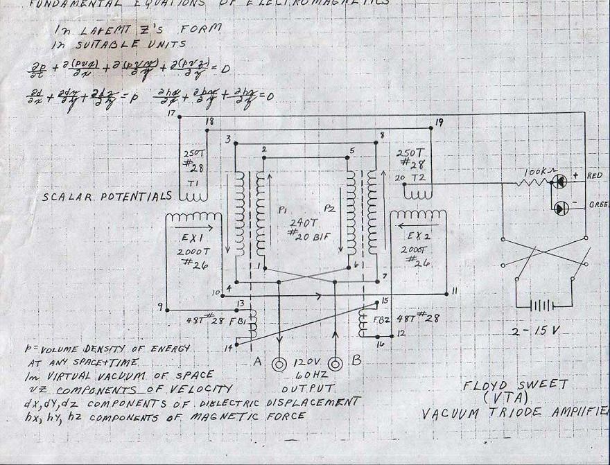
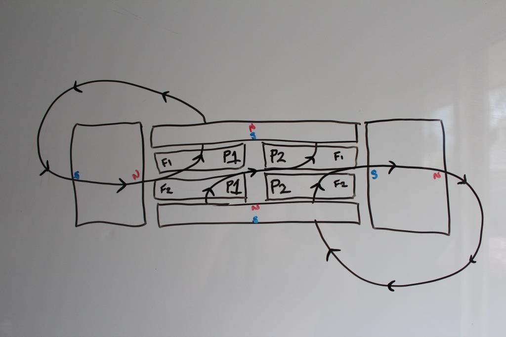
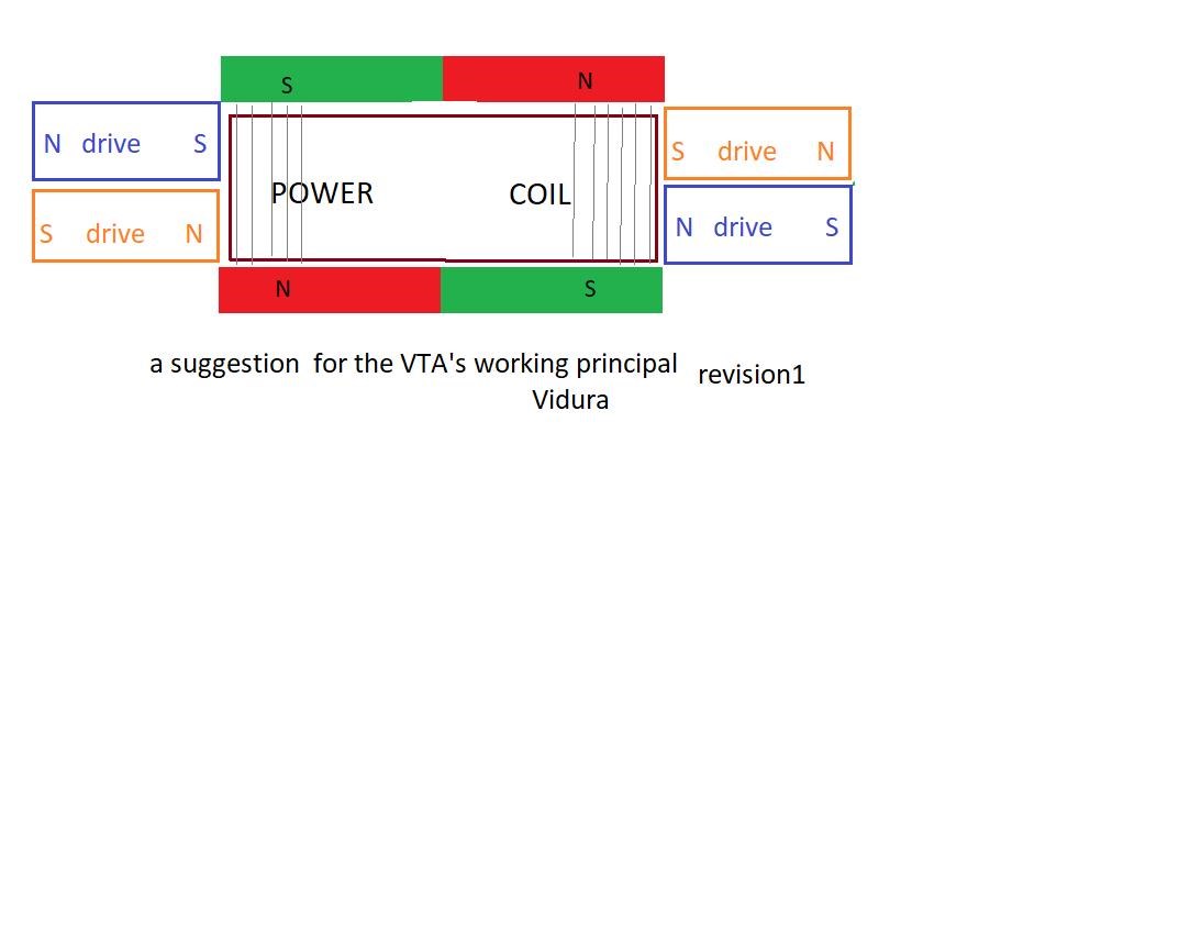
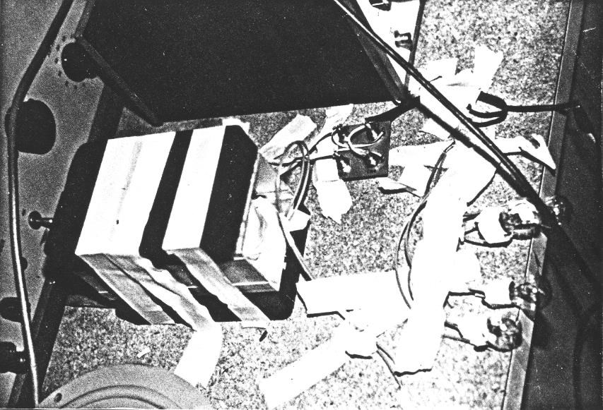
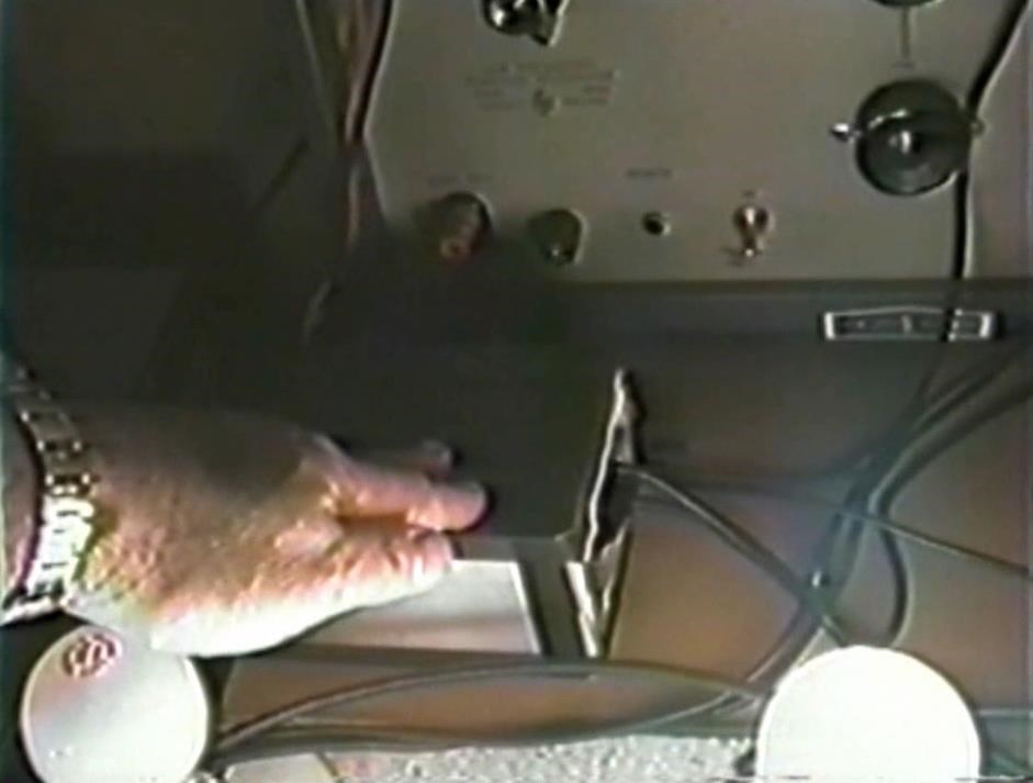
We must take this information and apply this to the VTA. What do we have, what do we need to achieve? We have three things:

  1. Magnetic Flux.
  2. Copper Conductors full of Charged particles!
  3. An application of Faraday's Law of Electromagnetic Induction. Thus a Voltage, measured to be 120 Volts in one machine.


Interestingly, if one takes the area under the Magnets ( 150cm x 100cm ) and does a basic calculation, we see a very close correlation:

Faraday's Law:
Area: 0.35 Meters (m) Squared or 35 cm squared.
Theta: 90 Degrees
B Initial: 0.0001 Tesla
B Final: 0.024 Tesla
Delta B: 2.0076 Tesla
Delta T: 0.0166666666666667 Seconds
Voltage: 120.456 Volts
Amperes: 1.7208 Amperes


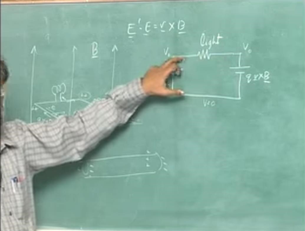
So if the Coil is 7 cm x 5 cm and we have a flux of 240 Gauss sweeping across the coil the the Coil will see an E.M.F of 120.45 Volts Induced.

So, mathematically, the Size and the Turns Floyd Sweet reported was very close to the real and actual Faraday's Law of Electromagnetic Induction calculations - This cant be just a coincidence.

   Chris

Vidura posted this 26 February 2020

Hey Chris and all following rereading the thread I would like to reply with respect to this post:

Hey Vidura,

Regarding your thread title: "VTA - new investigation, tests, a new attempt to replicate" I don't see what you mean here?

Are you attempting a Replication of the VTA?

This information is not new, its old: Mar 4, 2012.

All I was trying to do is clear up some confusion others had got themselves into because I posted Tom Bearden's Video Reference to Floyd Sweet being a Transformer Expert. It seems there is more confusion here on this thread.

I try so hard to avoid confusion, confusion is such a difficult thing to avoid. It does so frustrate me!

   Chris

For the question about replication the answer is yes, maybe not exactly the original work , but the principles applied. I saw that there is a whole lot of information on the hyic site, and of course there are also the vested interests present. Confusion arises due to lack of knowledge, when the knowledge becomes complete, all confusion will be dissipated, like the darkness when the light of the sun comes in the morning. As the device is something complex, I thought it would be a good idea to face it in diakoptic way, breaking it down in smaller parts. As the most important thing first I will dedicate to the principals of induction, and design some simple setups to test the concept of the moving flux-lines in different configurations. There is a lot of experimentation to do still.

Regarding the coils and the axis of magnetisation I found another theoretical possibility, but this has to be tested on the bench. A simple loop(coil) in a homogeneous field (say N S) would induce an EMF if the flux-lines would move in opposite directions from the center of the coils. There are different ways to force such a movement, but only experience will show how the aether reacts. By the way if someone know where ferrite magnets of big size can be obtained, the information would be appreciated. If in raw conditions unmagnetized, better, so different orientations could be tested. Thanks in advance. Vidura.

Chris posted this 26 February 2020

Hey, man

Faraday's Law:
Area: 0.35 Meters (m) Squared or 35 cm squared.
Theta: 90 Degrees
B Initial: 0.0001 Tesla
B Final: 0.024 Tesla
Delta B: 2.0076 Tesla
Delta T: 0.0166666666666667 Seconds
Voltage: 120.456 Volts
Amperes: 1.7208 Amperes

Do you know of a calculator for this? The one in the reference section does not match exactly. It receives radius as input instead of area.

Anyway, this is a fantastic observation. You are paying very much attention to details. Thanks for sharing!

EDIT: Something is wrong, probably Delta B: 2.0076 Tesla . I'm very interested in being able to play with the calculator you used for this post. Thanks!


Hey CD,

I have written a class, along with many other classes to calculate this:

///////////////////////////////////////////////////////////////////////////////////////////////////////////////////////////
///   ****************************************************************************************************************   //
///   Written by Chris Sykes                                                                                             //   
///   Copyrght 2016                                                                                                      // 
///   --> Application Name Goes Here <--                                                                                 // 
///                                                                                                                      // 
///////////////////////////////////////////////////////////////////////////////////////////////////////////////////////////
namespace EScience
{


    #region Using Statements:

    using System;

    #endregion


    public class FaradaysLaw
    {


        #region References:

        // See: http://farside.ph.utexas.edu/teaching/302l/lectures/node95.html

        /*

         * A plane circular loop of conducting wire of radius $r=10$cm which possesses $N=15$ turns is placed in a uniform magnetic field. 
         * The direction of the magnetic field makes an angle of $30^\circ$ with respect to the normal direction to the loop. 
         * The magnetic field-strength $B$ is increased at a constant rate from $B_1=1$T to $B_2=5$T in a time interval of  ${\mit\Delta}t=10$s.

         * What is the emf generated around the loop? 
         * If the electrical resistance of the loop is $R=15\,\Omega$, what current flows around the loop as the magnetic field is increased?
         * 
         * 
         * Answer: 

         * The area of the loop is  -  \begin{displaymath} A = \pi\,r^2 = \pi\,(0.1)^2 = 0.0314\,{\rm m}^2. \end{displaymath} 

         * The component of the magnetic field perpendicular to the loop is - \begin{displaymath} B_\perp = B\,\cos\theta = B\,\cos 30^\circ = 0.8660\,B, \end{displaymath} 

         * Where $B$ is the magnetic field-strength. 

         * Thus, the initial magnetic flux linking the loop is - \begin{displaymath} {\mit\Phi}_{B\,1} = N\,A\,B_1\,\cos\theta = (15)\,(0.0314)\,(1)\,(0.8660) = 0.408\,{\rm Wb}. \end{displaymath} 

         * Likewise, the final flux linking the loop is - \begin{displaymath} {\mit\Phi}_{B\,2} = N\,A\,B_2\,\cos\theta = (15)\,(0.0314)\,(5)\,(0.8660) = 2.039\,{\rm Wb}. \end{displaymath} 

         * The time rate of change of the flux is - \begin{displaymath} \frac{d{\mit\Phi}_B}{dt} = \frac{{\mit\Phi}_{B\,2}- {\mit\P... ...Delta}t} = \frac{(2.039-0.408)}{(10)}=0.163\,{\rm Wb\,s}^{-1}. \end{displaymath} 

         * Thus, the emf generated around the loop is - \begin{displaymath} {\cal E} = \frac{d{\mit\Phi}_B}{dt} = 0.163\,{\rm V}. \end{displaymath} 

         * Note, incidentally, that one weber per second is equivalent to one volt.

         * According to Ohm's law, the current which flows around the loop in response to the emf is - \begin{displaymath} I = \frac{{\cal E}}{R} = \frac{(0.163)}{(15)} = 0.011\,{\rm A}. \end{displaymath} 

         */

        #endregion


        #region Fields:

        // Magnetic Field B specified in the Constructor:
        private double B;


        #endregion


        #region Properties:


        /// <summary>
        /// Cross Sectional Area in Meters Squared.
        /// </summary>
        public double A
        {
            get;
            set;
        }


        /// <summary>
        /// Ohms Law can calculate the Amperes.
        /// Calculated as: I = V / R
        /// </summary>
        public double Amperes
        {
            get;
            set;
        }


        /// <summary>
        /// Initial B
        /// Calculated as: B = μNI/L
        /// </summary>
        public double BInitial
        {
            get;
            set;
        }


        /// <summary>
        /// Final B
        /// Calculated as: B = μNI/L
        /// </summary>
        public double BFinal
        {
            get;
            set;
        }


        /// <summary>
        /// Total Change in Magnetic Field B, through Area A.
        /// Calculated as: BFinal - BInitial = DeltaB
        /// </summary>
        public double DeltaB
        {
            get;
            set;
        }


        /// <summary>
        /// The Time Rate of Change of the Magnetic Flux in Seconds.
        /// </summary>
        public double DeltaT
        {
            get;
            set;
        }


        /// <summary>
        /// The Initial Magnetic Flux Linking the Loop.
        /// Calculated as: N A BInitial Cos(Theta)
        /// This Value is in Webbers.
        /// </summary>
        public double PhiB1
        {
            get;
            set;
        }


        /// <summary>
        /// The Final Magnetic Flux Linking the Loop.
        /// Calculated as: N A BFinal Cos(Theta)
        /// This Value is in Webbers.
        /// </summary>
        public double PhiB2
        {
            get;
            set;
        }


        /// <summary>
        /// The Resistance (R) of the loop of wire.
        /// </summary>
        public double R
        {
            get;
            set;
        }


        /// <summary>
        /// Theta (&theta 
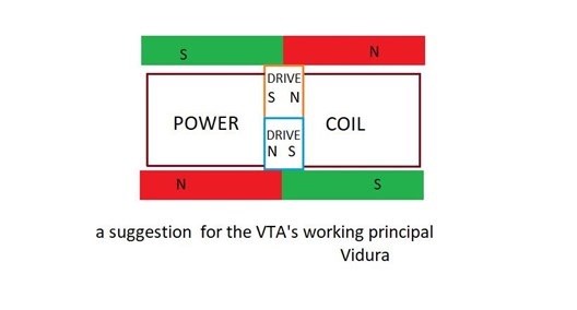
the Angle of the Magnetic Flux.
        /// This is the Angle away from Perpendicular (90 Degrees) from the Plane of the Conductor.
        /// </summary>
        public double Theta
        {
            get;
            set;
        }


        /// <summary>
        /// The Turns of the Conductor.
        /// </summary>
        public double Turns 
        { 
            get; 
            set; 
        }


        /// <summary>
        /// Time Rate of Change of the Flux in Webbers per second.
        /// One Webber per second is equivilent to One Volt.
        /// </summary>
        public double Wbs
        {
            get;
            set;
        }


        /// <summary>
        /// The Total E.M.F (Coulombs of Charge) measured in Volts.
        /// One Webber per second is equivilent to One Volt.
        /// 1 C is equal to approximately 6.24 x 10^18, or 6.24 quintillion
        /// </summary>
        public double Volts
        {
            get;
            set;
        }


        #endregion


        /// <summary>
        /// Initialises a new instance of Faraday's Law of Electromagnetic Induction.
        /// </summary>
        /// <param name="Radius">Radius of the Circular Conductor in Centimeters</param>
        /// <param name="NumberOfTurns">The number of Turns of the Conductor</param>
        /// <param name="Theta">The Angle, Perpendicular to the Plane of the Conductor in Degrees. E.G: If the Flux is at 90 Degrees, Theta will be: 0</param>
        /// <param name="BInitial">The Initial Flux Linking the Loop, often this will be Zero in Units of Tesla</param>
        /// <param name="BFinal">The Maximum Magnetic Field in Units of Tesla</param>
        /// <param name="DeltaT">The Time Rate of Change in Seconds - Frequency or Cycles per Second</param>
        /// <param name="Resistance">The Resistance of the Conductor</param>
        public FaradaysLaw(double Radius, double NumberOfTurns, double Theta, double BInitial, double BFinal, double DeltaT, double Resistance)
        {

            CalculateArea(Radius);

            this.Turns = NumberOfTurns;
            this.Theta = Helper.DegreesToRadians(Theta);
            this.BInitial = (BInitial == 0 ? 1 : BInitial);
            this.BFinal = BFinal;
            this.DeltaT = DeltaT;
            this.B = this.BInitial;
            this.R = Resistance;


            CalculatePhiB1();

            CalculatePhiB2();

            CalculateDeltaB();

            CalculateWebbersAndVolts();

            CalculateAmperes();
        }


        /// <summary>
        /// Initialises a new instance of Faraday's Law of Electromagnetic Induction.
        /// </summary>
        /// <param name="Length">Length of the Conductor in Centimeters</param>
        /// <param name="Width">Width of the Conductor in Centimeters</param>
        /// <param name="NumberOfTurns">The number of Turns in the Conductor</param>
        /// <param name="Theta">The Angle, Perpendicular to the Plane of the Conductor in Degrees. E.G: If the Flux is at 90 Degrees, Theta will be: 0</param>
        /// <param name="BInitial">The Initial Flux Linking the Loop, often this will be Zero in Units of Tesla</param>
        /// <param name="BFinal">The Maximum Magnetic Field in Units of Tesla</param>
        /// <param name="DeltaT">The Time Rate of Change in Seconds - Frequency or Cycles per Second</param>
        /// <param name="Resistance">The Resistance of the Conductor</param>
        public FaradaysLaw(double Length, double Width, double NumberOfTurns, double Theta, double BInitial, double BFinal, double DeltaT, double Resistance)
        {

            CalculateArea(Length, Width);

            this.Turns = NumberOfTurns;
            this.Theta = Helper.DegreesToRadians(Theta);
            this.BInitial = (BInitial == 0 ? 1 : BInitial);
            this.BFinal = BFinal;
            this.DeltaT = DeltaT;
            this.B = this.BInitial;
            this.R = Resistance;


            CalculatePhiB1();

            CalculatePhiB2();

            CalculateDeltaB();

            CalculateWebbersAndVolts();

            CalculateAmperes();
        }


        /// <summary>
        /// Calculate the Area of a Circle:
        /// </summary>
        /// <param name="Radius">The Radius of the Circle.</param>
        private void CalculateArea(double Radius)
        {

            // Circumference is: 
            // C = 2 * Math.PI * Radius

            // Area of a Circle is:
            this.A = (Math.PI * Math.Pow(Radius, 2)) / 100;
        }


        /// <summary>
        /// Calculate the Area of a Rectangle, or a Square from L x W.
        /// </summary>
        /// <param name="Length">Length of the Rectangle or Square</param>
        /// <param name="Width">Width of the Rectangle or Square</param>
        private void CalculateArea(double Length, double Width)
        {
            // Length x Width is:
            this.A = (Length * Width) / 100;
        }


        /// <summary>
        /// Calculate PhiB1. This Value is in Webbers.
        /// </summary>
        private void CalculatePhiB1()
        {
            this.PhiB1 = this.Turns * this.A * this.BInitial * Math.Cos(this.Theta);
        }


        /// <summary>
        /// Calculate PhiB2. This Value is in Webbers.
        /// </summary>
        private void CalculatePhiB2()
        {
            this.PhiB2 = this.Turns * this.A * this.BFinal * Math.Cos(this.Theta);
        }


        /// <summary>
        /// Calculate DeltaB from the Constructor Input.
        /// </summary>
        private void CalculateDeltaB()
        {
            this.DeltaB = this.PhiB2 - this.PhiB1;
        }


        /// <summary>
        /// Calculate the Webbers and Volts all at once, they are the same.
        /// </summary>
        private void CalculateWebbersAndVolts()
        {

            this.Wbs = this.DeltaB / this.DeltaT;

            this.Volts = this.Wbs;
        }


        /// <summary>
        /// Calculate the Amperes that the Conductor can Supply.
        /// </summary>
        private void CalculateAmperes()
        {
            this.Amperes = this.Volts / this.R;
        }

    } // END of Class...

} // END of Namespace...


It might be Delta B might need to be checked.

Best wishes,

   Chris

Chris posted this 05 March 2020

Hello Bladerunner and welcome!

Well thanks, I guess most days I feel sane at least. wink

Yes I got the Circuit in the video working, the trigger of the Cap was determined by the trigger circuit.

Zero Cross has a very different meaning from what we saw in was was posted as Floyd Cap Discharge circuits. Zero Crossing means when the AC Waveform is moving from one side of the cycle to the other, through the Zero Graticule Line on the Scope, from Positive to negative of from Negative to Positive.

However we saw Floyd Sweet triggering the Cap at the Peak of the AC Waveform. The waveform's were detailed in my videos.

So this is inconsistent information by definition.

All have their opinions, but unfortunately our opinions will not help us unless they are well educated Estimates. My problem is, none of the Magnet Conditioning Data fits with what Floyd Sweet was actually achieving inside the VTA! I should use the term SQM, the Space Quanta Modulator


was what Floyd Sweet named his machine before Tom Bearden, but the Vacuum Triode is also a good name as long as one knows how a Triode works. We just dont have enough information to accurately say what Floyd Sweet was actually doing!

What's important, is we have enough information to say we know what he was not doing!

Magnet Conditing as was shown to us, is not what we need to achieve! Damage to the Magnets was not what Floyd Sweet did, other wise this is impossible:

One just can not make the blades stand if there is any damage to the Magnets.


So, what are the solutions?

Others here are working on different theories, I think this is great! I can not say yet what others are working on, they are not open to publically sharing what they are doing yet, to be safe, keep safe, and just in case things don't work out I guess are the reasons.


The Black Box Syndrome

My Solutions are, what I call the Black Box Syndrome, We know we have an Output, Voltage and Current, this is where must start, we need to find what are the possibilities, Voltage, Current, Coils, Feed Forward and Feed Back loops, Input, can be Sine or Square wave, we certainly have what most would think of as a Transformer!

Two People quoted Floyd Sweet as being a Transformer Expert:

On rare occasions, Sweet saw this effect, called self-oscillation, occur in electric transformers

Ref: Jeane Manning: A New Physics for a New Energy Source / Free Energy - Making the Impossible Possible


Sweet was also a transformer designer and expert, and he remarked that he had also observed specialized self-oscillation in certain transformers.

Ref: Energy From The Vacuum by Tom Bearden


I found this Oscillation, where a very slight increase in Output can be seen, a System where the very Action of the Coils assists in the operation. We can verify that Floyd  Sweet was a Transformer Expert! We know from History many machines have come from the Transformer Background! Most Energy Machines have some Transformer theory in them somewhere!

Lester Hendershot, his Coils were a Resonant Air Core Transformer, in point of fact, most all the machines on my website hyiq.org Reference's, are based around the transformer in some way! Alfred Hubbard, Clemente Figuera, Daniel McFarland Cook, Don Smith, Andrey Melnichenko, Father Antonio D'Angelo, Melvin Cobb, Paul Raymond Jensen, Raymond Kromrey, Ruslan Kulabuhov, Steven Mark, and many more, so what if, with the evidence we have, Floyd Sweets VTA was more a Transformer than anything else?

We have evidence to support this!

Floyd Sweet wrote about one lay more than any other and his Coil Size supports his writings, Faradays Lay as Quantised by Newman.

Sticking to facts is super Important, we have many facts!

What I have introduced as Partnered Input Coils imply all of the above, its a type of Transformer, the Name can not be confused by any sane mind, One Input Coil, Two Output Coils, is of sorts a Resonant Transformer, Employing Electromagnetic Induction as those before us have, Employing Feed Forward and Back techniques, adding an Extra Source of Energy to the System, with the Third, or Second Output Coil, gives us a Gain in Energy, but only when Energy is "Generated" sufficiently.

The answers we have are a start, its not the VTA or SQL, but it fits the Naming conventions!

To make progress, we must force our minds to use Logic and Fact!

Best wishes,

   Chris 


bladerunner posted this 05 March 2020

Im not sure where you got your documents (not that it matters, I am glad you have them). But if its the same pack of documents that I got 30 years ago, there was one article in it that showed a diagram or SQM unit that used multiple 1x2x.5" magnets under aluminum foil tape. it was a single coil system that was reported to put out about 6 to 12W. It had a peculiar diode config in it. Do you have that paper? All my stuff is packed away in storage at the moment or I would upload it just to be sure. (maybe I best locate that)
The basic breakdown was a horizontal solenoid coil placed on top of what looked to me to be about 9 of those magnets on a piece of cardboard. This version I think was his first unit from which all others came from. perhaps because he did not have access to larger magnets? the fact he used multiple magnets indicates to me that there was no conditioning. Your statement about going down rabbit holes was pretty much right on the nose from my perspective. IE why would anyone want to build version .5 when there is a version 6? And such has been much of the experiments I have done. Always looking for the 1500Watts plus instead of trying to crawl before the run.

Thanks for the response.

Kent

Chris posted this 05 March 2020

Hey Kent,

I am sure if I looked I would have it there. 

Floyd Sweets idea, simply, as you point out is, Electromagnetic Induction. The Time Rate of Change of the Magnetic Flux in Proximity to the Conductor. Faraday's Law of Electromagnetic Induction.

Floyd Sweet took Induction to the next step, showing our 200 year old Law, is incomplete.

Best wishes,

   Chris

Chris posted this 07 March 2020

My Friends,

I do not wish to distract Vidura's new Thread: VTA-SQM research and replication, a builders club team project.

This is perhaps a better place for this anyway.

On the Topic and Point of Transformers and Floyd Sweet being a Transformer Expert, What are the turns Ratio we see: 1 : 5 = 48 Turns to 240 turns! So 240 / 48 = 5 right?

Ok, another point no one has ever bought up: 120 Volts / 240 Turns = â€­0.5‬ Volts per turn. 48 * 0.5 =  24 Volts, what did we use to start the VTA? 2 - 15 Volts right. So whats the chances the Turns Ratio are so close?

A Transformer? Yes of course the VTA is a Transformer variant!

We will always have those with their own opinion, however, an Educated Opinion has worth, an uneducated opinion is worthless! Beware those Un-Educated opinions! They will steer you down all sorts of Rabbit Holes!

The VTA was, plain and simple, a Generator and a Transformer all in one!

Best wishes,

   Chris

Chris posted this 12 March 2020

My Friends,

The above post, my last post on this thread, is super important, it sets the stage!

Of course, The Right Hand Grip Rule both pointing inward is equivalent to:


We also have the same Arrow Indicators in the VTA Diagrams or Schematics.

Lets be honest, what purpose would a very large sponge be under Generation two of the VTA:


In its current use, whats the purpose of the sponge? There can be only one use!

Its a noise dampening Sponge!

Why? Because Magnetic Fields, when they Buck, then have very noisy side effects! Lets see a small clip to verify this Fact:


So, Floyd Sweet had fixed the Vibrations in Generation Three, that were present in Generation Two, thus the big Sponge!

A quick example of Vibrations:


The Knocking Noise, listen carefully, this is the typical knocking noise and thus the Vibration I am talking about.

This example of Fact and Logic starts to paint a picture of the real direction Floyd Sweet was going, and makes magnet Conditioning even more Fake! It is obvious, Fact1 + Fact2 + Fact3 + FactN = VTA and many other Machines with very similar Operational Characteristics.

Best wishes,

   Chris

Chris posted this 07 June 2020

My Friends,

In recent threads over at ou.com, as part of the: Combined Effort Here and at OU.com, some members have tried again to push Magnet Conditioning! Users that are actively trying to push Magnet Conditioning are:

  • Smudge
  • partzman
  • Dansway


I am very much against the spread of information that can not be validaded, so, bluntly, I asked to see proof:

Smudge, if you have any proof that Floyd did anything that you claim with the Magnets, then please present the proof! I have proof to the contrary as you already know.

I would be super excited to see the proof you have to offer on your speculations on the subject at hand! Of course we all know how dire it is to have proof of direction of such Scientific Phenomena!

Lack of proof is speculation, and therefore not Scientific, and holds no water! Of course, I know, you know this. As any serious Researcher knows, it is very important to get ones facts straight, running down Rabbit Holes is of course not Scientific by any means! Wasting Funds on Speculation is not how Scientists operate!

I have a large vault of information on: Floyd Sweet, not a single shred of evidence to prove any modification to his Magnets, in point of fact there is evidence to say his Magnets were in Superb Condition and had a very good quality Magnetic Field.

Of course, I am talking Experimental Proof, not Speculatory Proof. Specifically in the area of: "oscillating field outside a permanent magnet". It should be noted: "transformer lamination" you speak of, it is an easy experiment, but only works when External AC Fields are present in the proximity of the Magnet and tuned to the frequency specifically. I have several videos on my website showing this. Even so, there is a very large problem in the Energy Transfer Mechanism inside this AC Field.

I am looking forward to you proving me wrong!

Best wishes, stay safe and well in these dire times,
Chris Sykes


P.S: I urge all Serious Researchers, Facts will not steer you wrong, Scientific Proof is critical in the path forward! Never ever take someone's word, always, ALWAYS look for the proof! Floyd Sweet was not a Materials Scientist, nor did he employ any as far as evidence goes! Proof will steer you in the right direction!

Ref: Me, EMJunkie, asking for proof of conditioning.


It needs to be noted: Cyril Smith, aka Smudge worked for Mark Goldes, which funded Floyd Sweet before Tom Bearden came along. So, if anyone has proof, or access to proof, it is likely going to be Smudge.

Needless to say, I got a rather unsuspecting response:


I do not know you have proof of the contrary.  What is your proof?  I do know you have a large repository of information from which it is clear you believe Floyd did not condition his magnets.  But your belief is not proof.  Ahern certainly did condition his magnet that showed the levitation.  I merely pointed out how that form of conditioning resulted in the levitation effect, and that has nothing to do with oscillating fields.

Smudge

Ref: Smudge's Response to Proof of Conditioning.


My Response:


Smudge, links were given, you can click the link to visit the Large Repository if you wish.

I am somewhat disappointed you offer no proof of Changes made to Floyd Sweets Magnets, and instead ask for my proof!

I have done many hundreds of experiments, the first and best proof is, the Image I gave. There is no way, one can make the Blades Stand on edge like was shown, if any Changes were made to the Magnets. Its a Fact that the Magnets have to be in superb condition, having a fully saturated Magnetic Field to make the Blades stand as they were.

The smallest amount of damage to the Magnetic Fields, the Blades wont stand as they were!

Energy Transfer Mechanism, if the Lateral Movement of Flux occurs as you explained, there can be no Energy Transferred, the Magnetic A Vector Potential does not induce a Voltage, as Flux Cutting does not induce a Voltage as the Lateral movement is uniform and the Coil becomes a dead short in this field.

It does only take a novice a few minutes on the bench to prove these simple Facts, with is experimental proof, and when Floyd Sweet said:

Laboratory experiments dealing with magnetic fields support the concept that magnetic flux may be modulated by low level oscillatory means.

However there is no lateral movement of flux. Rather, what happens is that the individual packets of quanta are polarized by the initiating and sustaining coherent force the field of the primary magnets or in special cases, electromagnets.

Ref: Floyd Sweet


Experimental Proof and verbal confirmation has now put this to rest. There was No Magnet Conditioning! Experimentally Proven!

I am sorry Smudge, we, you, I and all researchers have an obligation to make sure we do not mislead, or perpetuate those misleading stories that came before us! It is critical we expose the BS that has been evident for so long in this field!

"The Truth Shall Set You Free" - The Book of John, chapter 8, verse 32. I am not religious, instead Spiritual, so I believe this applies to all no matter what.

Ref: My response


Now, this is critical, any Scientist, at any level, should have proof of Scientific Direction, this is a very strange situation! Very strange indeed! Any Scientist would normally be happy to divulge at least a portion of the proof, even if it was mostly insignificant with others, especially those that they are attempting to convince colleges of the so called "Conditioning"!

After this, others, some unknown individuals join in and start getting all defensive! WHY? Why would they get defensive? This is completely odd and getting defensive as they are right now, only puts a much greater question mark over the story being told, or pushed here. Now, I am a reasonable person, if I make a claim, they would expect to see my proof, but turn the tables, then its not on!

As you all know, the Technology I am sharing, is step by step based on my research, experimental confirmations of Floyd Sweets papers, and words else where. So what I am sharing, IS Floyd Sweet, at least the early devices of Floyd Sweet, I mean any person with an ounce of common sense can deduce this:


I want you all to see this, as the on going struggle I am seeing, is truly just silly! Why would anyone in their right mind want to actively mislead others on the topic! I want to set the story straight, there is not a single bit of evidence to prove that Floyd Sweet made any modifications at all to his Magnets! In point of Fact, there is evidence to the opposite!

In Floyd Sweets Lab Notes, Zero Mention of Magnet Conditioning! The Machine worked!

We have machines, we all have differing outputs, but many of us have Above Unity Machines, a big achievement! Did we Condition any Magnets? No we did not! Many hundreds of other machines in History, none require any Magnet Conditioning except the SEG of John Searl, which has never been reproduced yet they still have a machine at least partially working.

Its time we all started to question these Amazing Claims:

Extraordinary claims require extraordinary evidence

Ref: Carl Segan


We will never make progress if we blindly follow tall stories that have never had any associated proof! We must be Logical about this!


The above video is extremely important, it is proof of action! What did the so called Conditioning do? Then why would an Oscillator be needed? Turn on the Magnets? Hahaha come on!

Best wishes, stay safe and well My Friends,

   Chris

Chris posted this 07 June 2020

My Friends,

I never thought I would witness this, Free Speech is gone, moderated out of Open Discussion:

I have removed all the posts concerning Chris's remarks on conditioning and levitation, as this is a distraction from the subject at hand.  I am pleased that Whoopy has replicated the same levitation feature that Ahern did, it is easily explained from the field pattern and has nothing to do with the how the Sweet or Manelas devices worked.  If someone else wishes to make use of this feature then please create another thread devoted to that subject.

Smudge


My Friends, please, I urge you, beware what you read!

I have said all along, stick to what you can Prove, Stick to Facts only! Unproven fairy tales, are not Science and the Scientists that push Fairy Tales, are to be wary of!

Best wishes, stay safe and well,

   Chris

Chris posted this 08 June 2020

My Friends,

I posted this, for others, to show them some basic facts, facts I already know you all know, but for those that may not:


Did Tarriel Kapanadze Condition his Magnets? To get 5 KW from his Coils? Oh, No, That's right he has no Magnets! Logic My Friends, there is no Magic if you use Logic!

Think Logically in these dire times, don't go down Rabbit Holes! Use deduction to deduce where the Energy comes from! There is No Magic!

When there is ONLY The Coils, and the Power Flows, then what does this tell you?


Quote from: Ruslan Kulabuhov


All these systems operate on the basis of standing and traveling waves. It is necessary first to catch the motion of particles in the coil.


Don't let yourself be another statistic of the dumb club! Floyd Sweet told you straight:


Quote


If the directions of the two signals are such that opposite H-fields cancel and E-fields add, an apparently steady E-field will be created. The energy density of the fields remain as calculated above, but the value of the E-field will double from E / 2 to E.


Quote


FIELD SUPER-POSITION AND THE VACUUM TRIODE

Electromagnetic induction with no measurable magnetic field is not new. It is well known that in the space surrounding a properly wound toroidal coil there is no magnetic field. This is due to the superposition of the fields. However, when alternating current is surging through a transformer an electric field surrounds it. When we apply the principle of superposition to the vacuum triode it becomes more obvious how the device is in fact operating.

The principle of superposition states that; "In order to calculate the resultant intensity of superimposed fields, each field must be dealt with individually as though the other were not present". The resultant is obtained by vector addition of each field considered singularly.


Consider for a moment the construction of the triode which includes the bifilar coils...

When the current in one half of the conductors in the coils (i.e., one of the bifilar elements in each coil) of the device is moving up, both the current and the magnetic field follow the right-hand rule.

The resultant motional E-field would be vertical to both and inwardly directed.

At the same time the current in the other half of the conductors in the coils is moving down and both the current and magnetic field follow the right-hand rule.

The resulting motional E-field is again vertical to both and inwardly directed.


Thus, the resultant field intensity is double the intensity attributable to either one of the set of coil conductors taken singularly.

Expressed mathematically: E = (B x V ) + ( -B x -V ) = 2 ( B x V )


The term: "double the intensity" what exactly does this refer to? Yes that's right, a Standing Wave! Very good!


Same Tech, see the clarity of Logic! Now why would you need "conditioned magnets" when, like hundreds of others have, Tariel Kapanadze, Ruslan, Akula, and many hundreds more get Kilowatts from their coils with no extra work! Honestly, Logic will not steer you wrong! Fiction will! At the very most, on a hot day perhaps Air Conditioning may help some? But seriously, don't be a statistic! Think Logically!

Dont believe me? Go read the documentation, from Floyd Sweet himself: Floyd Sweet Documents.

My Members are all, already well aware of these simple facts! I guess that's another reason why they are so far ahead!

P.S: If you do enough research, the Elementary Electric "Generator" operates on the very same Standing Wave principles.

Ref: Me, Chris


This may be of use to new comers here? If you have not already, please go and read the documentation: Floyd Sparky Sweet. Tons of dots to connect there.

Copper or I2R losses remain but may be minimized by using wire of larger than usual cross-sectional area.


Best wishes, stay safe and well in these dire times,
   Chris Sykes

Augenblick posted this 31 July 2020

An interesting development in conditioning non-magnetic substances to become magnetic.

https://twin-cities.umn.edu/news-events/research-brief-fools-gold-may-be-valuable-after-all

With this in mind, the idea of using

...a process called “electrolyte gating” – using an electrolyte-rich solution, “comparable to Gatorade,” and small applications of electrical volts to move around molecules and make the substance magnetic.

“We were pretty surprised it worked,” Leighton said.

“By applying the voltage, we essentially pour electrons into the material,” he explained. “It turns out that if you get high enough concentrations of electrons, the material wants to spontaneously become ferromagnetic (potential magnets), which we were able to understand with theory.”

Leighton said their goal was to manipulate the magnetic properties of materials with a voltage alone, with very little electrical current, which is important to make magnetic devices more energy-efficient. Progress to date had included turning on and off ferromagnetism, the most technologically important form of magnetism, in other types of magnetic materials. Iron sulfide, however, offered the prospect of potentially electrically inducing ferromagnetism in an entirely non-magnetic material.

Just as a bias frequency is needed to make recording tape more linear, consider that a biasing current may cause a magnet or ferromagnetic material to become more or less inductive/conductive/magnetic ... changing the threshold for the inflow of aetheric energy.

What think ye?

-A-

Chris posted this 01 August 2020

I agree with CD,

Everyone should draw their own conclusion and use their better judgment.


Gather all the facts, then make your own decisions based entirely on the facts you gather. Make sure you have the best path forward before you invest time and money into a very expensive and time consuming area!

Reference to Fighters post: John Bedini is not correct - All Floyd's Coils were Under the Magnets and the Field waving across the Coils does not produce a Voltage. See all my prior posts. This is a simple fact that needs to be gained to see where we have been misled by others.

Best wishes, stay safe and well My Friends,

   Chris

Chris posted this 24 February 2020

Hey Vidura,

Leave it for the moment, its ok, we will sort it later on.

   Chris

  • Liked by
  • cd_sharp
  • Augenblick
Chris posted this 27 July 2020

Hello and welcome Kritischer!

I have always tried to say follow your gut feeling!

If you feel Magnet Conditioning is a path you need to follow and Prove / Disprove then we will read and listen to your posts!

At the same time, I ask people to think Simple and think Logically!

If you can build a machine that requires No Magnet Conditioning and works with 99% similar characteristics to the VTA and at a thousandth of the Cost and of the Time, then I urge all to make the decision for themselves.

Here at Aboveunity.com, we are actively building machines that output excess energy! We have many examples! Reading through our pages shows many machines either close to or well above the Unity Boundary. None of the machines we build need anything special, only requirement is Understanding of the topic at hand.

A Crystal Lattice can vibrate, normally at very high frequencies, in the MHz range or higher:


Am I of the opinion that this can be done with a Permanent Magnet, possibly, is it practical, no its not, not for power! Why? Laterally moving Fields are no good for Induction. The Fields must vary in Amplitude, this in my opinion is in the realms of Advanced Materials Science and not practical for the average person and possibly not even possible at all!

Remember: There is more proof against Magnet Conditioning than for! There is no proof Floyd Sweet had special Magnets at all! The only argument for Magnet Conditioning is a few sentences saying so, that's all! Not enough evidence to support a case! Magnet Conditioning is nothing more than Speculation and Hearsay! A Narrative pushed by those that want no progress on such devices!

You sound wise! The decision is yours and yours alone, what path you decide to take! We can offer you help with practical machines, easy to build once one has an understanding, if you are willing to put in the work?

Best wishes, stay safe and well,

   Chris

  • Liked by
  • cd_sharp
  • YoElMiCrO

Topic Is Locked

We're Light Years Ahead!
Members Online:

No one online at the moment


What is a Scalar:

In physics, scalars are physical quantities that are unaffected by changes to a vector space basis. Scalars are often accompanied by units of measurement, as in "10 cm". Examples of scalar quantities are mass, distance, charge, volume, time, speed, and the magnitude of physical vectors in general.

You need to forget the Non-Sense that some spout with out knowing the actual Definition of the word Scalar! Some people talk absolute Bull Sh*t!

The pressure P in the formula P = pgh, pgh is a scalar that tells you the amount of this squashing force per unit area in a fluid.

A Scalar, having both direction and magnitude, can be anything! The Magnetic Field, a Charge moving, yet some Numb Nuts think it means Magic Science!

Message from God:

Hello my children. This is Yahweh, the one true Lord. You have found creation's secret. Now share it peacefully with the world.

Ref: Message from God written inside the Human Genome

God be in my head, and in my thinking.

God be in my eyes, and in my looking.

God be in my mouth, and in my speaking.

Oh, God be in my heart, and in my understanding.

Your Support:

More than anything else, your contributions to this forum are most important! We are trying to actively get all visitors involved, but we do only have a few main contributors, which are very much appreciated! If you would like to see more pages with more detailed experiments and answers, perhaps a contribution of another type maybe possible:

PayPal De-Platformed me!

They REFUSE to tell me why!

We now use Wise!

Donate
Use E-Mail: Chris at aboveunity.com

The content I am sharing is not only unique, but is changing the world as we know it! Please Support Us!

Thank You So Much!

Weeks High Earners:
The great Nikola Tesla:

Ere many generations pass, our machinery will be driven by a power obtainable at any point of the universe. This idea is not novel. Men have been led to it long ago by instinct or reason. It has been expressed in many ways, and in many places, in the history of old and new. We find it in the delightful myth of Antheus, who drives power from the earth; we find it among the subtle speculations of one of your splendid mathematicians, and in many hints and statements of thinkers of the present time. Throughout space there is energy. Is this energy static or kinetic? If static, our hopes are in vain; if kinetic - and this we know it is for certain - then it is a mere question of time when men will succeed in attaching their machinery to the very wheelwork of nature.

Experiments With Alternate Currents Of High Potential And High Frequency (February 1892).

Close