Electromagnetic Waves

  • Topic Is Sticky
  • 2.1K Views
  • Last Post 20 September 2021
Chris posted this 31 March 2017

We are all at different levels of research, some researching different areas. 

I think one important thing to keep in mind is Waves! All waves! Electromagnetic, or Waves on the beach all exhibit the same characteristics!

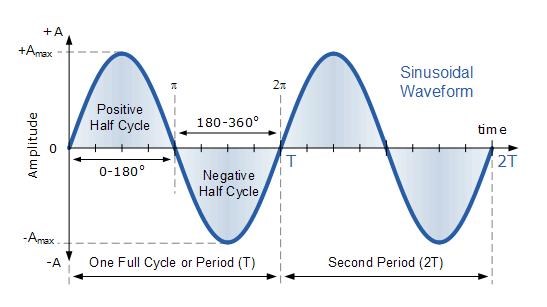
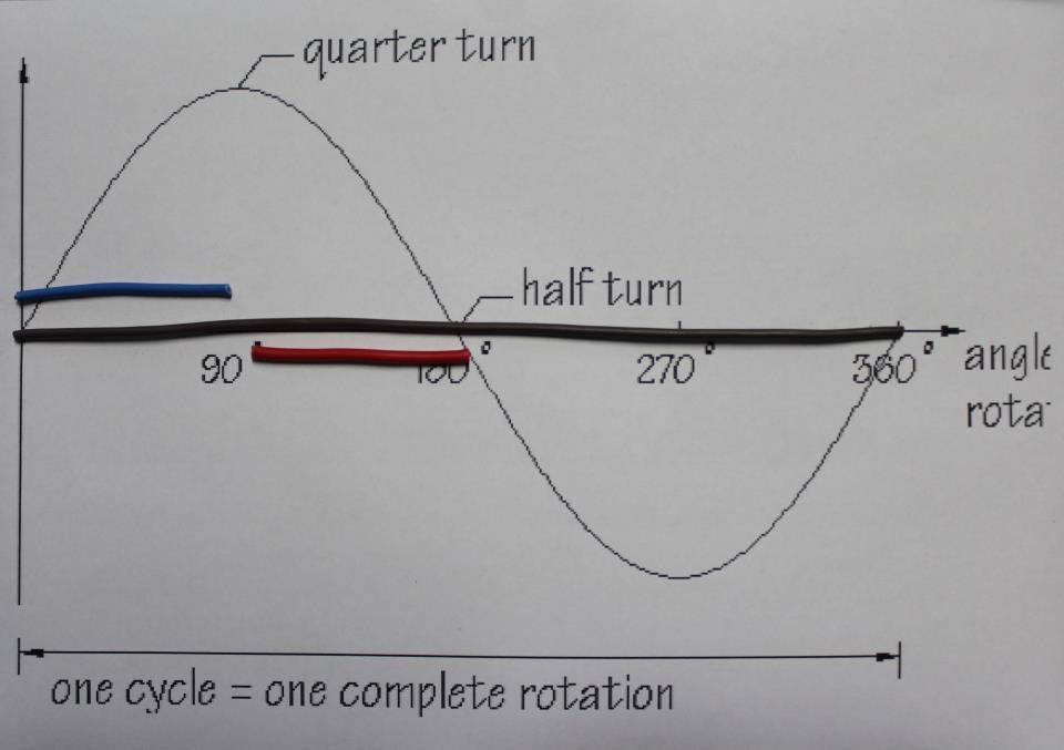
Some basics on Waves:


Standing Waves:


Another Interesting video:


Simple but effective:


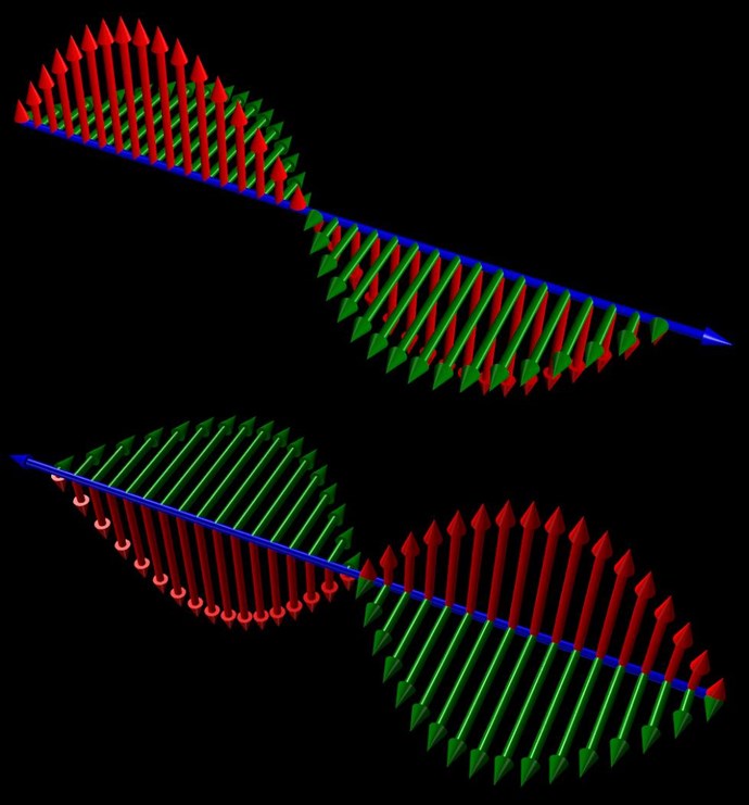
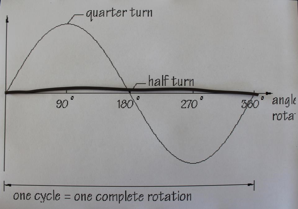
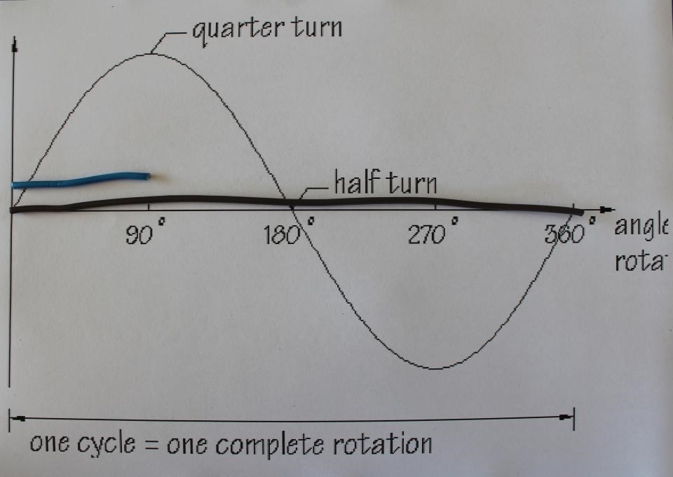
My point of showing these videos is to show that two waves when interfering can very easily create different effects just from a small amount of tuning!

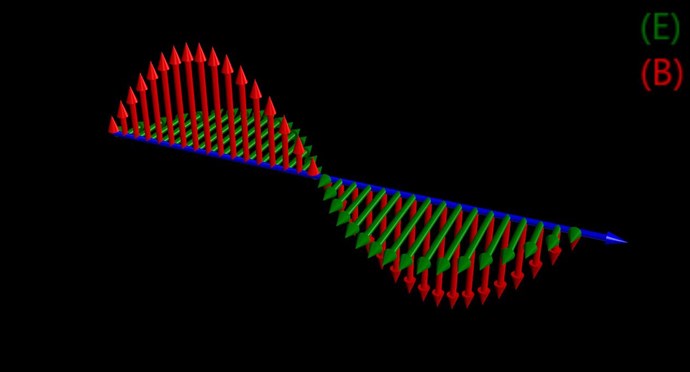
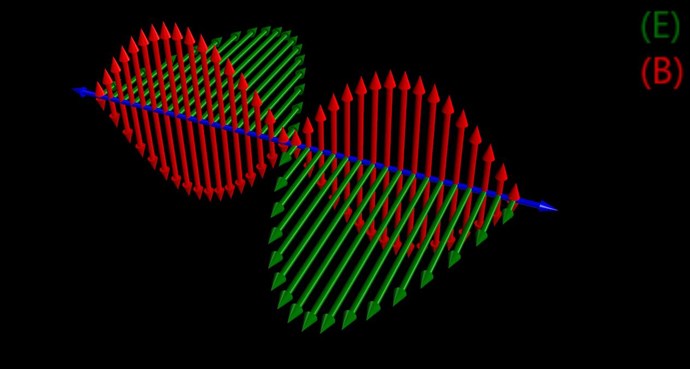
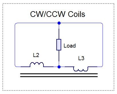
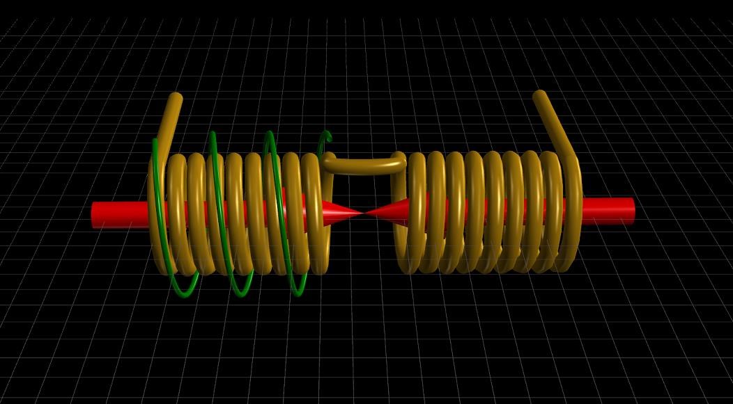
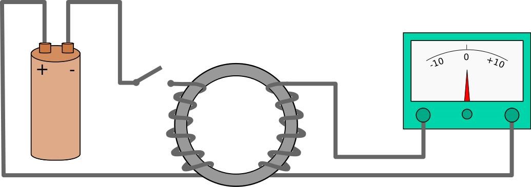
A Coil of Wire, carrying a Current will produce a Magnetic Field, this very Magnetic Field needs to be thought of as a Wave, subject to all the same laws that the above Videos show. This Magnetic Interference is Electromagnetic Induction!

Types of Waves:

  • Longitudinal Waves - Movement of the particles are parallel to the motion of the energy.  Sound waves moving through the air is an example of this type of wave.
  • Transverse Waves - movement of the particles are at right angles (perpendicular) to the motion of the energy. Movement of a wave through a solid object like a stretched rope or a trampoline is an example of this type of wave.
  • Surface Waves - particles travel in a circular motion.  These waves occur at interfaces.  Examples include waves in the ocean and ripples in a cup of water.  One consequence of occurring at an interface is that the motion of the particles diminish with distance from the interface.  The further from the interface the smaller the rotation of the particles until as some distance from the surface, there is no more movement or energy propagation.
  • Shear Waves - Can travel in all directions away from the epicentre of an Earthquake. Shear waves on the other hand have larger amplitudes and travel at a slower
  • Lamb Waves - Lamb waves propagate in solid plates. They are elastic waves whose particle motion lies in the plane that contains the direction of wave propagation and the plate normal (the direction perpendicular to the plate)
  • Love Waves - In elastodynamics, Love waves, named after Augustus Edward Hough Love, are horizontally polarized surface waves. The Love wave is a result of the interference of many shear waves (S–waves) guided by an elastic layer, which is welded to an elastic half space on one side while bordering a vacuum on the other side.
  • P Waves -  A type of elastic wave, and are one of the two main types of elastic body waves, called seismic waves in seismology, that travel through a continuum and are the first waves from an earthquake to arrive at a seismograph.
  • Rayleigh Waves - A type of surface acoustic wave that travel along the surface of solids. They can be produced in materials in many ways, such as by a localized impact or by piezo-electric transduction, and are frequently used in non-destructive testing for detecting defects


I hope this helps everyone!

   Chris


Order By: Standard | Newest | Votes
Chris posted this 03 October 2020

My Friends, a re-post from here: Current and Voltage Amplification key to Energy Machines

Excellent reference material and also excellent quotes/questions!

This is a real problem when an understanding is to be achieved! We see two issues:

  • The Magnetic Field ( B ) and the Electric Field ( E ), are Orthogonal to each other and technically 90 degrees out of Phase. I show Current as E, with no Phase difference, and not Voltage for simplicity.
  • It is not stated clearly, at any time, in most papers, which part of the Wave is a Standing Wave, Electric or Magnetic.


The answer is: Any wave form can be a Standing Wave! But for Energy "Generation" we MUST have opposing Magnetic Fields, thus creating a Standing Current Waveform, this, the Current Wave is at 90 degrees to the Magnetic Wave form:

I know you know all this, but for the other readers:


Electromagnetic Wave:


The Direction of the wave is in the direction of the Blue Arrow. The Wave Length is: λ = v / f - Where v is the speed of light in the medium one is using, and f is the Frequency.


Standing Wave:


Two Wave Forms, each in opposite Directions, shown by the Blue Arrows. In this case, equal in Amplitude. However we see the Current Waveform, depicted in Green as ( E ), has double the amplitude. This waveform is a Standing Wave, two Current Waveforms traveling in opposite Directions Summing.

The Wavelength for a standing wave is: 0.5 λ

Floyd Sweet told us:

If the directions of the two signals are such that opposite H-fields cancel and E-fields add, an apparently steady E-field will be created. The energy density of the fields remain as calculated above, but the value of the E-field will double from E/2 to E.

A very interesting description by Wikipedia:

In one dimension, two waves with the same wavelength and amplitude, traveling in opposite directions will interfere and produce a standing wave or stationary wave. For example, a wave traveling to the right along a taut string held stationary at its right end will reflect back in the other direction along the string, and the two waves will superpose to produce a standing wave. To create a standing wave, the two oppositely directed waves must have the same amplitude and frequency. The phenomenon can be demonstrated mathematically by deriving the equation for the sum of two oppositely moving waves.


Please forgive my inaccurate depiction, but the following is supposed to show two waves equal, but travelling in opposite directions, the Arrows in the Current Waveform are in the same direction:


However, the Arrows in the Magnetic Waveform are in opposite Directions! 

Of course, the top and bottom waves in the above Image, when combined, create the wave below: A Standing Wave is the Current depicted in Green, which has double the Amplitude of each wave by itself.


So, the Current, because we know Standing Waves exist and we know how they are created, we know that this will Add, to create a Standing Wave.

Remembering, any wave can be made to be a Standing Wave, Magnetic, Water, Sound, light, hmm interesting...

We can build Noise Cancelling Headphones, but cant apply this Tech to Power?

   Chris

Jagau posted this 11 October 2018

Well done video explaining RF transmission line problems.

On our days all systems that i worked have impedance of standard 50 ohms impedance.

We can see if we are near the transmitter all problems with near object causing with stray capacitance with direct view on scope .

Exxellent video.

Jagau

Chris posted this 30 April 2017

While on the Path of discovery we strike problems, some stay unsolved for what seems an eternity!

Recently I believe I have solved one of those problems! 

For a long time we have pointed out the significance of the One Quarter Wavelength, actually the Great Nikola Tesla has given us this Secret for some 100 + Years...

A quarter-wave impedance transformer, often written as λ/4 impedance transformer, is a component used in electrical engineering consisting of a length of transmission line or waveguide exactly one-quarter of a wavelength ( λ ) long and terminated in some known impedance.

This Secret is a key component in these devices!

One tell tail sign is in the Turns Count, or the Voltage difference! By doing some quick Math, you can see there is a 1/4 Ratio - Approximately.

Vin = 240

Vout = 60

Ratio = 60 / 240 = 0.25 = 1/4

Please Note: Some devices do not use the 1/4 Wavelength and get to the same end result by other means, but majority do and this is critical to understand on the path of discovery!

What is a One Quarter Wavelength? The Wavelength is a Degree of Rotation, and one Cycle is 360 Degrees, this means 1Hz is equal to One Cycle per Second or One Hertz for a Sine Wave:

You can see, One Quarter Wavelength is in the middle of the peak, on the first Positive Half Cycle! Right dead in the middle!

So, the significance, if we take a piece of wire with a length of x and lets say x = 1. Now this piece of Wire is our Primary Coil, on our Transformer but its currently in front of us, as a straight piece of Brown Wire:


Now, we can see, One Cycle is applied across this piece of Wire, Our Primary Coil (Brown Wire). Now the Secondary Coil (Blue Wire) has a length of y = 0.25, this will make more sense soon:


The Secondary Coil (Blue Wire), ends at a completely different part of the Cycle, One Quarter Wavelength is Peak Amplitude of the Cycle! The Primary ends at Full Cycle, which is Zero Amplitude.

Now comes the part I am still working on:

Partnered Output Coils are Two, Separate, Distinct Coils! Each having a length of y = 0.25 or One Quarter Wavelength, so this times two is 1/2 Wavelength! Or is it?

Because our basic Circuit is as follows:

The One Quarter Wavelength still holds for each Coil, we have Secondary, or Partnered Output Coils that have Magnetic Fields that will Oppose, each Current in the Coil, combined, will Reflect a Net Zero Force back on the Primary!

More Soon!

   Chris

Chris posted this 20 September 2021

My Friends,

I would like to share a story of an amazing device, we see a similar thing in our work, when we have resonance.

The device is called: Passive Cavity Resonator


I hope some understanding is seen here, and we can see why and how Our Partnered Output Coils work and why they must be in Resonance, they are doing the same thing, Passive Resonators:


I hope this post is usefull and others can gain some greater understanding here.

Best Wishes,

   Chris

Chris posted this 31 March 2017

In the following video, one can see Transverse Waves combining to create Standing Waves in many occasions:


Mostly on the shore line! I have seen Waves Waves in the Ocean that slap together to create Wave Heights very much bigger than the original Wave Heights! 

Please Remember, when Floyd Sweet said:

If the directions of the two signals are such that opposite H-fields cancel and E-fields add, an apparently steady E-field will be created.


Similarly, if two signals flow through each other in such a way as to give the appearance of a steady magnetic field as a result of their E-field cancelling it is easily shown using the above equations to cancel out H and c so that:

This means, one of the following quantity's, Electric or Magnetic, in the Electromagnetic Wave, One MUST Cancel, or Oppose, to satisfy this statement:

The energy density of the fields remain as calculated above, but the value of the E-field will double from E/2 to E.

So, by having an Opposition of two Magnetic Fields, we create a Standing Electric Field that is Double the Amplitude of each of the Singular Electric Transverse Waves!


It is important to note: This is exactly how an Electric "Generator" Works, there is no difference!

Lenz's Law - Is the Magnetic Opposition of each the Source and Generating Coils:


Please remember, Electrical Energy IS Mass, Matter, the Charged particles that make up the Copper Wire are the Electrical Charge, waiting for our machines to Separate these Charged Particles! This is Einsteins Mass Energy Equivalence!


I hope this helps!

   Chris

  • Liked by
  • Scorch
  • Entilzha
Chris posted this 01 May 2017


Partnered Output Coils do use 1/4 Wavelength, but the total of each separate Coils is 1/2 Wavelength - See:


More soon!

  • Liked by
  • cd_sharp
  • ISLab
Chris posted this 01 May 2017

A requirement of "Resonance" has been mentioned by many Inventors, many using LC Resonance, but these Inventors do not mean LC Resonance! A different Resonance is intended and has been pointed to by only a few.

The following quote's are by Floyd Sweet. This document is titled: "Magnetic Resonance" - A very good name for such a phenomena!

Electron spin resonance is a technique used in the lab for measuring this splitting

using radio freq, technology

Alfred Hubbard was the first I know to talk about Magnetic Resonance in these devices:

Referring to the Jensen machine stated: natural magnetic resonance freq = 2.80GHz

the nuclear magnetic resonance of a free electron when charges in magnetic states are

induced by magnetic field the changes in states causes a condition called electron

paramagnetic resonance, or EPR. The EPR of a free electron is 2.80 H MC. Where H is in

gauss. This should be the initial state of the defining mathematical format.

Dealing with Resonance at High Power Levels.

Resonance frequencies may be maintained quite constant at high power levels so

long as the load remains constant. We are all familiar with AM and FM propagation, where

in the case as AM, the voltage amplitude varies, and with FM, the frequency is modulated.

However, the output power sees a constant load impedance, that of the matched

antenna system. If this changes, the input to the antenna is mismatched, and standing

waves are generated resulting in a loss of power. The frequency is a forced response and

remains constant. Power is lost and efficiency becomes less and less, depending on the

degree of mismatch. Let’s assume the Jensen amplifying transformer is in a resonating

condition. Its output is connected to a transmission line which is X number of miles long.

Without any customer load at all, power will be required to change the line.


  • X = 1 (Brown Wire)
  • y = 0.25 (Blue Wire)
  • z = 0.25 (Red Wire)

Where x is our Primary Coil (Brown Wire), y is one Secondary Coil (Blue Wire) and z is the second Secondary Coil (Red Wire). y + z = 0.5 or 1/2 Wave Length. One Half Wavelength is the optimum length for a wave as described in the above video.

If this Wavelength is not matched, then as Floyd Sweet explains, we get Standing Waves, of the wrong type, and we loose the effects we are looking for! Remembering The Magnetic Field is doing all the work! We need to get the Magnetic Fields at Maximum to do more and more work! 

And so, we want to bring about Magnetic Resonance! Also known as EPR or Electron Paramagnetic Resonance! This is done with at least two external Magnetic Fields as Floyd Sweet explains:

Electrons revolve about the nucleus of an atom and spin around their axis. In addition, the nucleus has a spin of its own. All of these moving charges have associated magnetic fields (magnetic moments), and magnetic resonance is concerned with the interactions of some of the fields with each other, and with at least two external magnetic fields applied to the atom.

I want to quote some else, SR193, known as SReason when releasing his work:

Any schoolboy knows that the electromagnetic field performs work in both the transformer and the generator, but there are conditions under which the field can not do the work, then some actions are taken that it can perform work.

The Mass, or Matter, the Atomic structures of the Copper Conductor is the Source of Energy, Matter as a Fuel, where Matter is abundantly available!

Note: Alfred Hubbard, Floyd SweetRoman Karnaukhov, SReason are just some that talk about this Resonance


It is important to note: Electron Spin Resonance Machines are very simple Machines!!!


  • Liked by
  • cd_sharp
  • ISLab
Chris posted this 01 May 2017

SR193 also wrote:

Hello again. I want to clarify a few points: 


1) Kapanadze in his first video speaks the pure truth, the only thing his notions and yours may diverge, HP: the same resonance. 

2) Kapanadze did the right thing, that he brought the arrester to the "street" (outside the box), since if the discharge does not light up, it will be focal, so he was worried for the spark throughout the whole film. 

3) The device uses two effects, only in a complex they produce a result. The arc has a wide spectrum, several of these frequencies are resonant for the "ferromagnet", which causes the processes defined in it.


A field appears. But the field is "dead" and the work can not perform, so the second process is connected. In sum, these two processes serve to obtain excess energy from a ferromagnet and this energy does not come from the air. And more: A ferromagnet can be represented as a material, where there are very many small magnets, which in the form of hausa are directed in different directions and can not create the resulting field.


The first process allows them to relax, the second to turn around so that all these small magnets create the resulting powerful field. To put it simply, a powerful magnet with the ability to control is created. Well, then the matter of classical physics. In occasion of my cinema, who wants to see in it falsification, that will necessarily see. This is the nature of man. I would also like to ask the forum participants, if possible, not to take away the information of this forum on other forums.

Which implies he was well versed in the Processes involved!

Alfred Hubbard talks about the same thing: Page 38 / 58

Notice the use of Sub Harmonics of the Base Frequency: 2.8Ghz

Note: A "Dead" Field is a key Term! What is a "Dead" Field? It is a Non-Inductive Field, Bucking Coils, or I prefer Partnered Output Coils, that exhibits no Effect back on the Primary as was said:

 Any schoolboy knows that the electromagnetic field performs work in both the transformer and the generator, but there are conditions under which the field can not do the work, then some actions are taken that it can perform work.

  • Liked by
  • cd_sharp
  • ISLab
Chris posted this 08 November 2017

Hi Team, I found some more reference data:


Hard to get any real good data on this, but its a start. It shows that, Transmissions lines are subject to 1/4 Wavelength theory.

In Faraday's first experimental demonstration (August 29, 1831), he wrapped two wires around opposite sides of an iron ring or "torus" (an arrangement similar to a modern toroidal transformer).

Based on his understanding of electromagnets, he expected that, when current started to flow in one wire, a sort of wave would travel through the ring and cause some electrical effect on the opposite side. He plugged one wire into a galvanometer, and watched it as he connected the other wire to a battery. He saw a transient current, which he called a "wave of electricity", when he connected the wire to the battery and another when he disconnected it. This induction was due to the change in magnetic flux that occurred when the battery was connected and disconnected.

Electromagnetic induction - Wikipedia

I want to draw your attention to the use of the word: Wave

Note, as pointed out in the Video, 1/4 + 1/4 is 180 degrees, and out of phase! Equal and Opposite.

   Chris


  • Liked by
  • cd_sharp
  • ISLab
Chris posted this 07 October 2018

My Friends,

Our oldScientist Friend has a very good Video I want to share:


I have pointed out before, Coils must be thought of as have Waves, Elctromagnetic Waves.

The OldScientist has also done some experiments and confirmed Partnered Output Coils in the following Video:


   Chris

  • Liked by
  • cd_sharp
  • ISLab
Chris posted this 02 May 2017

Devices where Partnered Output Coils are used, will exhibit many Magnetic Fields:

  • Primary Magnetic Field
  • Secondary PO Coil one
  • Secondary PO Coil two
  • Secondary PO Coil one lenz
  • Secondary PO Coil two lenz

So we have a total of Five Magnetic Fields here, there is also one more, a positive affect Field on the Primary, where the Primary Magnetic Field can see an assisting Field from the action of the Secondary Fields, so a total of Six Fields all up.

Tom Bearden tried to point this out in the Whittaker Papers, attached below.


Attached Files

  • Liked by
  • electrondiger
Chris posted this 12 May 2017

Hi Jo - Can you please clarify, which video? 

Please note the videos on this page, only some are of my own work/research, some are others videos that I have used, because they are very good at showing what I am trying to get across.

Yes, there is a difference between w and ω

Not always easy to insert symbols into some Digital Data, but using the Unicode will help some most of the time: http://www.dionysia.org/html/entities/symbols.html

Anyway, for all reading, please be aware, a lower case w might sometimes be Omega ( ω ) which is Radians most of the time.

   Chris

  • Liked by
  • ISLab
vfedtec posted this 14 May 2017

Howdy Chris,

it's the one titled '25. One Dimensional Waves...' near the beginning of this thread.

Unfortunately the nearator pronounces it as w rather than omega. That's where for some confusion can set in.

Otherwise it is clear by context that omega t is meant.

Cheers

Jo

  • Liked by
  • Chris
vfedtec posted this 11 May 2017

Hi Chris,

in video 25. on this page you use the term w instead of lower case omega which can be VERY confusing for the novice in this field. Perhaps this issue has been addressed already.

Cheers

Jo

Chris posted this 17 May 2017

Ah yes, that video is from Kahn Academy, Sal, he is a genius! No doubt a slip of the Pen, he will defiantly know about Omega Symbol.

   Chris

We're Light Years Ahead!
Members Online:

No one online at the moment


What is a Scalar:

In physics, scalars are physical quantities that are unaffected by changes to a vector space basis. Scalars are often accompanied by units of measurement, as in "10 cm". Examples of scalar quantities are mass, distance, charge, volume, time, speed, and the magnitude of physical vectors in general.

You need to forget the Non-Sense that some spout with out knowing the actual Definition of the word Scalar! Some people talk absolute Bull Sh*t!

The pressure P in the formula P = pgh, pgh is a scalar that tells you the amount of this squashing force per unit area in a fluid.

A Scalar, having both direction and magnitude, can be anything! The Magnetic Field, a Charge moving, yet some Numb Nuts think it means Magic Science!

Message from God:

Hello my children. This is Yahweh, the one true Lord. You have found creation's secret. Now share it peacefully with the world.

Ref: Message from God written inside the Human Genome

God be in my head, and in my thinking.

God be in my eyes, and in my looking.

God be in my mouth, and in my speaking.

Oh, God be in my heart, and in my understanding.

Your Support:

More than anything else, your contributions to this forum are most important! We are trying to actively get all visitors involved, but we do only have a few main contributors, which are very much appreciated! If you would like to see more pages with more detailed experiments and answers, perhaps a contribution of another type maybe possible:

PayPal De-Platformed me!

They REFUSE to tell me why!

We now use Wise!

Donate
Use E-Mail: Chris at aboveunity.com

The content I am sharing is not only unique, but is changing the world as we know it! Please Support Us!

Thank You So Much!

Weeks High Earners:
The great Nikola Tesla:

Ere many generations pass, our machinery will be driven by a power obtainable at any point of the universe. This idea is not novel. Men have been led to it long ago by instinct or reason. It has been expressed in many ways, and in many places, in the history of old and new. We find it in the delightful myth of Antheus, who drives power from the earth; we find it among the subtle speculations of one of your splendid mathematicians, and in many hints and statements of thinkers of the present time. Throughout space there is energy. Is this energy static or kinetic? If static, our hopes are in vain; if kinetic - and this we know it is for certain - then it is a mere question of time when men will succeed in attaching their machinery to the very wheelwork of nature.

Experiments With Alternate Currents Of High Potential And High Frequency (February 1892).

Close