Current and Voltage Amplification key to Energy Machines

  • Topic Is Sticky
  • 11K Views
  • Last Post 03 March 2020
Chris posted this 28 October 2018

My Friends,

A thread was posted: current amplifier as key to the free energy, one which we are very familiar with already!

It seems we have started a new push, an awakening, here in the West, where our Russian friends in the East, are a long way ahead of us!

It appears most of us understand the required principles, but most perhaps may not understand the putting into practice side of things.


A Reminder:

Current Amplification: Non-Inductive Winding at Resonance


Voltage Amplification: Standard Transformer Winding.


We can make the next Generations existence a comfortable one, we have the power to change the world forever!

   Chris


Order By: Standard | Newest | Votes
Chris posted this 03 March 2020

Hello and welcome Kelech!

By the sounds of things, we need to get you a new dedicated thread of your own so you can share yoour work, We are a super friendly bunch of people here so you will not get any trolling here at all!

Our forum is run with very tight guidelines!

So please feel free creating your own thread and posting your work there. Please pm me if you need help!

Thank You for sharing your work!

Best wishes,

   Chris

  • Liked by
  • electrondiger
  • Mimo
Kelech posted this 03 March 2020

If not clear about this, you can email me at kelekehsci@gmail.com

  • Liked by
  • Chris
Kelech posted this 03 March 2020

I have another method of generating efficient power using Homopolar setting.... You will need small strong magnets to move round a fixed conducting disk similar to balls of a bearing. The arrangements is similar to two bearings with connections between the balls inside them. Power collecting coils arranged facing the balls in the bearings such that as the ball move arround the bearings like the earth revolving around the sun and still turning about it axis. This a planetery Homopolar generator system. Just understand the solar planer arrangements and you will be able to build the planetary homopolar generator....

  • Liked by
  • Chris
  • Mimo
Kelech posted this 03 March 2020

It is very true that Resonance is certainly a key to tapping into the see of energy in the universe. Another method is modifing a Homopolar generator such that Lorenz force is balance or over ride by other force. A careful analysis shows that it's visible to create balance in the entire system. My study shows that Lorenz force and other forces I discovered actually leads to zero drag on the rotating disk. First secrt I like to share is to use counter rotating disk arrangement with special current collectors to create the balance and possible over unity on the system. This is real!!!!

  • Liked by
  • Chris
  • Mimo
Chris posted this 22 November 2018

Hi Atti,

Excellent observations and Videos! Thank you for sharing! On our MEG Thread, you will find some data that is similar, and I would like to post your video there also, for others to reference.

The Non-Linear Inductance introduced by the series MOV's and Resistor switching in, shorting the second coil, is a key and a little tricky to get occurring. Some Fiddling is required.

Keep in your mind NON-Linear Inductance! Also, research Jim Murrays Transforming Generator:


I have also shown these Effects in my PDF and here: Reduced Impedance Effect

I am not sure the term: Non-Linear Inductance is the right way to describe these effects, but you can see what's going on.

Thanks for sharing!

   Chris

  • Liked by
  • ISLab
Atti posted this 22 November 2018

I would like to introduce you to a Hungarian inventor's job. He called it a magnetodynamic generator. No one has ever been able to reproduce the device, but we can find many interesting information in it that resembles the arrangement of others. For example, Chris or others are transformers. There are not two output coils here but four. This is what confirms Chris and others' work.I have struggled with him unsuccessfully, so I have not been dealing with him for some time, but I have to keep in mind.It's not long enough.I'm interested in reading it here:

https://overunity.com/4300/a-truly-overunity-transformer-meg/msg217851/#msg217851


1: 57: 00 is one of the roll coils and one part of the condenser and the subsequent device. Both transformers are valid for coil and condenser pairs of bonds. The two transformer capacitors are connected together. That is why they form a common oscillating circuit.
The inventor's explicit statement: "If the primary and secondary windings are placed in parts of a vibration circuit, the entire system - the system of controlled primary and secondary windings - becomes two nonlinear oscillating circuits."
Therefore, secondary loads should be taken at a pulse rate.
Of course, this is not a sacred script, but it is advisable to consider it as others:
Mr Preva, Graham Gunderson, ......

More good work for everyone! 

  • Liked by
  • Chris
  • alohalaoha
Atti posted this 22 November 2018

 Hello everyone! You've been tagging out the output coils of the transformer and its effects. Now, I'm also agreeing with some video. I do not say that everything is accurate and good. But I've tried a lot of settings. And most importantly, I measured the output and incoming power. Pulse Width Adjustment is most commonly fooled and bogus. So I tried to achieve a pure color tension at low frequencies. So far I have not found any significant positive results. Although there are sometimes surprises. It's just an example. It appears at the end of the video below.

  • Liked by
  • Chris
  • alohalaoha
Chris posted this 22 November 2018

My Friends,

It astounds me, so many people have devoted their lives, and life's savings, to learning this technology. Some going to their graves keeping the secrets they learned. One person after another, all doing the same thing.

I ask you, is there any rhyme to this reason?

We know from our studies and experiments, several criteria must be met.

  • Non-Linear Inductance: I = dL/dt
  • An LC Tank on the Input helps, see my pdf document: Guidelines to bucking Coils. Circuits I released years back, below:
    • LC Tank Resonance gives a greater mean Current and Voltage amplitude, for the same Input.
  • Often a Tuning is required.


I posted the above schematics at: overunityresearch.com/ ( 2015-02-01 ) various other places after also.

An example of CW/CW is here:


I stated in my document above, some coils work and some don't, however this is entirely dependant on the device and the situation. I wish I had not used these analogies now learning more about this field as some of these Coils Geometry's do in-fact work.

So, I ask you, stay open minded. If it does not work one way, it very well may work another way. At the time of writing this document I was investigating AC Partnered Output Coil configurations, an not so much DC at the time.

DC Configurations are very much more flexible.

I can only do so much to share what I have learned. None of my Videos can help any more than the videos before mine, but what is here in these pages, once read and understood is very valuable and could save a lot of time and money for others.

   Chris

alohalaoha posted this 14 November 2018

There is also POD 2

http://www.geocities.com/theadamsmotor/pod2.html

Try at: https://web.archive.org/web/*/http://www.geocities.com/theadamsmotor/pod2.html

Aloha


Attached Files

  • Liked by
  • Chris
Chris posted this 14 November 2018

Hey Aloha,

Nice, reminds me of some of Wistiti's work, also similar to Skywatchers work! These experiments are very important!

   Chris

  • Liked by
  • alohalaoha
alohalaoha posted this 14 November 2018

Hey Chris

Analyse this POD device with KPD =2 (C.O.P) from 2002. Same CW-CCW partnered configuration switched inside kolbasa (ring magnetic conductor) and simple triggering circuit.

Another blob in the ocean of FE devices !!

Summary of Device Testing Results To Date

3.7 W average 1 hour power consumption of  isolated motor when connected directly to the battery source, with no other connected circuitry (drop the reading across the battery terminals) 

 41.3 W  Disconnected battery prior to over-unity test: 

39.4 W Disconnected battery after test over-unity:

1.9 W Total power consumption with John's transductor device

COP 2.0  50% of normal draw using a DC electric motor as a load - basic setup

COP 1.4 A lower figure was obtained with an incandescent lantern bulb


ps: You should enable rar archive attachment !!

Regards

Aloha

Attached Files

  • Liked by
  • ISLab
Vidura posted this 14 November 2018

Hi aloha, The same happens to me and many others, but we always should be aware that there ar so many people with much greater difficulties than one, which have to deal with hunger, war or diseases, so the problems we have will become small, and certainly there will be better times in the future

alohalaoha posted this 14 November 2018

Hey Chris !

Thanks. I have got many different ideas how to, but as always my biggest problem is a cash to implement them in the hardware.

Without a working device and free electricity in my place all my ideas are like a sand in the desert.

Current situation is not so pink for me !!


Regards

Aloha


Chris posted this 13 November 2018

Hey Aloha,

Nice! Certainly gets the mind working!

   Chris

alohalaoha posted this 13 November 2018

My variant of Mr.Preva device. I called him ETA or ....

ETA


  • Liked by
  • Chris
Jagau posted this 13 November 2018

yes and in addition he uses an E core as in the Menichenko video

who proved the O.U. concept wtih this kind of setup.

I believe it is also another secret to the proper functioning of this lantern.


Jagau

  • Liked by
  • Chris
Chris posted this 13 November 2018

My Friends,

There is beauty in Logic!

Akula's devices, most all of them, had the Feed Back Loop we saw in The Mr Preva Experiment and also is standard in most all Energy Machines. We saw it in Floyd Sweet's VTA, and many others. I like the Akula Schematic, it has beauty:


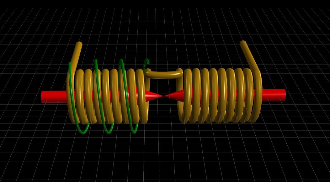
L1 and L2 are the same as The Mr Preva Experiment, Current is 180 Degrees out of phase, equal and opposite, but in Magnetic Resonance. The Standing Wavelength is equal to the length of the Wire.

Follow the Arrows my friends, Tiger2007's schematic also has the same arrows on it, thanks to Aloha for sharing. Don Smith:

From Page 31 of Dons PDF.


Floyd Sweet:


and many others exist.

   Chris

Chris posted this 11 November 2018

My Friends,

At the absolute base level, the Insulated Copper Conducting Wire is a Door Way to the Universal Space Field: The all Mighty Aether, The Quintessence, or The Higgs Field, what ever you wish to term this Atomic Machine of Universal Access to Charge!

An Insulated, Copper Conductor, with ends bared, but Why?


Sub-Atomic Particles are an Engine of Spacetime. The answers are on this Thread.

   Chris

alohalaoha posted this 10 November 2018

As in Russia said: ALL NEW IS LONG TIME FORGOTTEN OLD.

Non inductive discharge coil (distributed capacitance coil). Again great Nikola Tesla and his non inductive bifilar. The year is 1890.

Make attention that one half of coil must have greather lenght and number of windings with respect to other half. The direction of windings are as always CW-CCW. And strong disharge through TT spark.


alohalaoha posted this 10 November 2018

I was found this extremely interesting schematic of Tiger2007 experiment in my archive.

Same principle also has been involved here. Amazing how i felt looking at his schematic with partnered secondary of Tesla transformer.

What is amazing he had used asymmetric partnered coils where one partnered coil half is wounded CCW amd its lenght is exactly 1/4 wire lenght of other partnered half CW coil. What specially amazed me is a wounded primary (copper bars) height of Tesla transformer (shortly TT) is exactly 1/4 height of seconday coil. As we already know TT secondary was tuned with lambda/4 wavelenght of pulsing operation here at frequency 35,1KHz.

Here you can download totaly free (not shareware) excellent program for calculating and designing almost all types of winding coils. There is also english version of this in 32 and 64-bits format.

http://coil32.ru/coil32-win32.html


  • Liked by
  • Chris
Chris posted this 09 November 2018

My Friends,

A critical point to observe: Why do we need to achieve Resonance?

Floyd Sweet Wrote:

We are all familiar with AM and FM propagation, where in the case as AM, the voltage amplitude varies, and with FM, the frequency is modulated.

However, the output power sees a constant load impedance, that of the matched antenna system. If this changes, the input to the antenna is mismatched, and standing waves are generated resulting in a loss of power. The frequency is a forced response and remains constant. Power is lost and efficiency becomes less and less, depending on the degree of mismatch.

Ref: http://www.hyiq.org/Downloads/Magnetic%20Resonance%20by%20Floyd%20A.%20Sweet.%20PH.%20D.pdf


Now, we must think of Resonance and what it means!

Resonance:

In an electrical circuit, the condition that exists when the inductive reactance and the capacitive reactance are of equal magnitude, causing electrical energy to oscillate between the magnetic field of the inductor and the electric field of the capacitor.

Note 1: Resonance occurs because the collapsing magnetic field of the inductor generates an electric current in its windings that charges the capacitor and the discharging capacitor provides an electric current that builds the magnetic field in the inductor, and the process is repeated.

Note 2: At resonance, the series impedance of the two elements is at a minimum and the parallel impedance is a maximum. Resonance is used for tuning and filtering, because resonance occurs at a particular frequency for given values of inductance and capacitance. Resonance can be detrimental to the operation of communications circuits by causing unwanted sustained and transient oscillations that may cause noise, signal distortion, and damage to circuit elements.

Note 3: At resonance the inductive reactance and the capacitive reactance are of equal magnitude. Therefore, ωL = 1/ ωC , where ω = 2πf , in which f is the resonant frequency in hertz, L is the inductance in henrys, and C is the capacity in farads when standard SI units are used. Thus,

f = π / 2 sqrt(LC)

Ref: https://www.its.bldrdoc.gov/fs-1037/dir-031/_4576.htm


Consider the Length of Wire, this is very important!

Capacitance between the Windings, Distributed Capacitance, and the Inductance, give rise to an LC Tank, where Resonance is achieved at a certain Frequency. This is where Inductive Reactance ( XL ) and Capacitive Reactance ( XC ) are Equal and thus cancel each other out. Both XL and XC have a value, but the Affects of each other Counter Balance, thus no XC or XL effects are seen.

A  Standing Wave, therefore is seen, at the exact Length of the Wire:


The 1st Harmonic has a Wavelength calculated by: L = 1/2 ⋅ λ, or a Harmonic there of, is the exact length of the Partnered Output Coils. The Insulated Copper Conductors, our Output Coils, are a Wave Guide:


So, we know for sure, as was stated in the above Quote from Floyd Sweet, at the time of this writing, he did not know how this technology worked.

We do not see: "...standing waves are generated resulting in a loss of power. The frequency is a forced response and remains constant. Power is lost and efficiency becomes less and less, depending on the degree of mismatch."

This does not happen.

We have NO reflection, no Impedance! The match of the Standing Wave, Wavelength, and the Output Coils are exactly the same!

Now, this post is perhaps the most important posted, so please, if you do not understand this post please ask!

@Vidura, hope all is well now, Storm Damage can be extensive. Agreed! Many devices used this Tech! @Aloha and Jagau, thanks for info!

   Chris

  • Liked by
  • alohalaoha
  • ISLab
Vidura posted this 09 November 2018

Hi Team, I was out a couple of days due to thunderstorm damage on internet repeater sistem. Regarding the noninductive coils and the Interaction with E fields I was thinking about this lately .It is straightforward that the cancelled Bfields give rise to a doubled Efield(standing wave). And it is likely to be a bidirectional effect, so that this coils can be "activated" by a pulsing Efield.This could be tested with a simple experiment. I believe that this principle is involved in the Hubbard Device, as it is stated that his assistants knew how to wind the non inductive coils, but where not able to activate them, also I remember a image of this device which had attaching a car ignition system! High voltage pulses. It was a standart ignition system from a 8 cylinder motor and had 8 outer coils. I think this make sense, as there also is stated that the coils had a kind of shielding(capacitor plates).

Chris posted this 08 November 2018

My Friends,

Our Study of the Lorentz Force gives us a grasp of the Magnetic Field and the Current that moves in the Wire.


We know also, that Electromagnetic Induction is based around the Lorentz Force:


This is how Electrons are Freed and forced to Move as a Current. Electromagnetic Induction has Holes in the theory, we know for sure this to be true and have proof of it, so the procedure is a little more complicated than this. The basics are as Follows:


This video being required study!


SO, as the Currents Oppose, the Magnetic Fields Oppose, The Lorentz Force predicts this and its experimentally verifiable. We know from The Mr Preva Experiment that at Resonance, Current is Amplified, each Current is 180 Degrees out of Phase, equal and opposite, due to the Standing Wave Created.

Standard already known Laws of Science explain where the Energy is coming from, its just that they have not been correctly interpreted and applied to Power Engineering!

   Chris

alohalaoha posted this 08 November 2018

Yes Jagau

Accordin to Tesla the most important field we must study is a Static field (in my oppinion wrong formulation, because nothing is not static in his primary state). So called Static field is kind of Teleport between Aether and our Material world.

Worth reading:

https://archive.org/details/WilliamLyneOccultEtherPhysicsTeslasHiddenSpacePropulsionSystem2ndEdition1997

https://archive.org/details/PentagonAliens1993-WilliamLyne

https://archive.org/details/LyneOccultDictatorship_201710

Best regards

Aloha


Jagau posted this 08 November 2018

Hi Aloha

Do youy mean highly static negatively charge?


Jagau

  • Liked by
  • Chris
alohalaoha posted this 08 November 2018

What happen when we pulsing Tesla non inductive bifilar with tube capacitor highly negatively charged (deeply under gnd) with HV pulses from the primary at Tesla's MFT configuation ?

Imagine it like old Tesla's triode with Tesla's coils....

Pimary = Anode, Tube capacitor = Catode, Non inductive bifilar = Grid, NF transformer = H-field source, HV impulse = Class C triode work, Tesla's pancake coil = Radiant Energy Converter ( call it Scalar field (Nikolaev), motional E-filed (Hooper), Steady E-field (Sweet), Radiant (Tesla) or whatever you want.

"THERE IS NO ENERGY IN THE MATTER , EXCEPT IN THE AETHER" - TESLA

Dissociation of molecular H2 Hydrogen to monoatomic H1 Hydrogen in the HV arc of two vanadium electrodes , and immediately recombination of H1 monoatoms to molecular H2 on the surface of vanadium catalist, with high thermal energy output boost is a proof of Tesla's claim.

  • Liked by
  • Chris
Chris posted this 07 November 2018

My Friends,


Now look at that Coil:


Which is the very basis of:


Video from: 


In your mind, ask why:


The Coil is NON Inductive for exactly: 8 Turns, exactly like we have been told by many before us, and we saw in the Inductance Experiment above. Akula had the Tariel Kapanadze Grenade Coil there!


Repost; Relevant for the above Images from Andrey Melnichenko


An Experiment worth doing, for the knowledge gained:


Inductance Experiment:


Temporarily connect the shortest paths to ground for each Coil as indicated.

Take an Inductance Meter, and measure the points indicated: L2 and L2 Gnd, record, and L1 and L2 and record.


Expected Results:

The Inductance Meter should give a greater Inductance Value for the XMM1 configuration compared to the XMM2 configuration.

This means, the Inductance is partially cancelled. The magnetic Fields will oppose for the most part for the equivalent lengths of L1 and L2. This is the Current Amplification component of the Energy Machine.

   Chris


NOTE: CD_Sharp has done this experiment and kindly shared the results. Thank You CD!


   Chris


P.S: This Thread alone, makes all other Forums look like new born babies! We are LIGHT YEARS ahead of the other forums!

Chris posted this 07 November 2018

My Friends,

A day of down time again, no response from my hosting company as to why... Endless problems. Back up now and that's the main thing!


Resonance

Floyd Sweet wrote a document, its one of the best ones I have studied! Magnetic Resonance by Floyd A. Sweet. PH. D.

I again want to quote a statement that confirms other statements:


So, a Skeptical mind, and rightly so! Resonance in a standard Scientific mind will not hold as Load changes. This is true for a standard LC Tank Circuit that has no Re-Generative Properties! This is easy to prove on the bench, as a Load is changed a standard LC Tank Circuit does in-fact loose Resonance as stated by Floyd Sweet!

Tariel Kapanadze talked about a Resonance also:


Don Smith also said the same thing:


What Don Smith talked about is exactly correct. What's not being considered or understood, by skeptical minds, is the fact that Damping by Inductance actually is reversed, by adding Current to an LC network, the LC Resonance can be sustained, because the Resistance is reduced and also the Impedance along with the total Inductance which is proportional to the Magnetic Field which is proportional to the Current Drawn:


The underlying principal (forget Millikan’s experiment) has been derived in that magnetic effects vary on the square of the current. As the load on the machine increases, the volt-ampere product increases.

The rate of flow of charges increases. Quantum mechanics state not all electrons in copper are free to carry charges. Then it’s time to set the wheels in motion to free them from binding magnetic forces.

Once this is done, conductivity will improve and resistance decrease as we are dealing only with electrons. Copper will not change to another metal as atoms which are mostly empty space would have many electrons to spare anyway. 

Ref: http://www.hyiq.org/Downloads/The%20Space-Flux%20Coupled%20Alternator.pdf


So, an LC Resonant Machine, incorporating Magnetic Resonance, where each Current is 180 Degrees out of Phase, Magnetic Fields Opposing, can and does sustain Resonance as Load Impedance changes.

We have a wealth of proof on this fact!

How both the current and potential windings are assembled into the stator winding assembly is proprietary.

The current and potential windings require relatively little power, and are applied in such a manner that rate of flow of moving charges may be accelerated beyond 1 Ampere = 6.24 x 10¹⁸ electrons per second. Thus the duty factor of the copper changes. Losses diminish and more charges drawn from the now coherent space field flow at a faster rate as current to the load. This means as more current is required by varying loads more feedback magnetomotive forces free more electrons from binding forces complimented by potential magnetic forces of the orientated, coherent space field. Thus a conductor that formerly had a temperature rise above ambient labelled as a factor of 10 would now operate at a temperature of 1.0. Thus the same gauge wire would carry 10 times more current at the same temperature.

Even better results may be forthcoming. The energy conversion conservation is fantastic. On a separate sheet will appear a derived equation of long series of partial differentials that dispute many textbook expressions defining fields produced by moving charges. The equation is simplified to a point that may be understood by most rational people.


Andrey Melnichenko said:

False step more than once led to the discovery of new roads. (Leszek Cumorah) 


So, think different, backwards, because we have been taught to look past this fact!


NOTE: This fact is not known in Science, they, the physicists do not understand how Magnetic Resonance works. Basically, the Feedback Circuit Pumps Current! We have build an Electron Pump! A Forced Response to adding Load.

   Chris

Chris posted this 06 November 2018

Apologies,

I post only to share. I believe what I have learned, and the slow introduction of this knowledge, to be very important for all Humanity!

I have to thank all here, reading and learning, please remember, I have said before, I am also learning as I move forward on my path of discovery.

Using the method of Cross Referencing gives credibility to what I am sharing. This is why I try to cross Reference everything.

   Chris


P.S: Before I introduced Partnered Output Coils, One in a Thousand had part of the puzzle, where they knew Bucking Coils had potential. We know today, the importance and why, what they do and how they do what they do, where Charges come from and what makes them move and how to Accelerate them. Current Amplification is already in our reach, we know how to do it! Voltage Amplification also! We have broken ground that none before us have broken! We have already changed the world!


Thus, the reason we are seeing the Successes we are seeing, understanding has been reached.


  • Liked by
  • Jagau
  • ISLab
Jagau posted this 06 November 2018

It can not be clearer than that

Jagau

  • Liked by
  • electrondiger
  • Chris
Chris posted this 06 November 2018

My Friends,

It should be considered, the spatial coordinate of Partnered Output Coils, where each Coil is located and the way, or the Direction of the Windings, for some may be difficult to grasp:


Fig: One


Fig: Two

The two Coils are identical except for the spatial coordinates of the Coils. In the top image, if the second winding, to the right, were wound on top of the winding on the Left, the two coils, Fig one and Fig Two, would be identical.

The Coils Buck, they are Magnetically Opposing each other, and we know this "Generates" excess Current ( I ) but only when the Coils are in Magnetic Resonance.

I hope this is something to think about for others here.  Again, we have seen this for quite sometime, many different people have given this to us:


Floyd Sweet


The current and voltage initiating fields are in such a direction to either accelerate or decelerate the rate of flow of charges depending on the applied polarity and voltage amplitudes.

As polarity may be maintained constant, that polarity of acceleration should be chosen so charges move at faster rates, lowering copper duty factor, at the same time opening the gates wider so more coherent field entities may enter for the conversion process.

It’s obvious, we have a self-regulation machine whose inherent conservation to the nth degree.


Ref: Floyd Sweet


Andrey Melnichenko


Tariel Kapanadze


Don Smith


It must BURN the Trolls that used to Troll me, to know I am right, to know I bought the Light, where there was only darkness, where the so called Educated ones Dwelled... Light Up The Darkness!


Where:

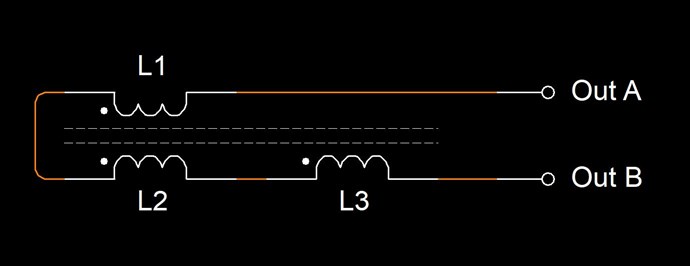
  • L1 and L2 are Non Inductive and are Current Amplification Windings. L1 and L2 Inductive component is almost Zero.
  • L3 is Inductive and is a Voltage Amplification Winding.
  • LA1 is the +1000 Watts Load


And many other examples exist.

   Chris

Chris posted this 06 November 2018

Hey Vidura,

I believed this thread would have cleared up much confusion. There are answers in this thread that some, no doubt,  have sort after for quite sometime.

Its often the simplest thing, the simplest answer to the most complex problem. The inductance Experiment will help greatly in understanding.

   Chris


  • Liked by
  • electrondiger
Vidura posted this 03 November 2018

Chris, totally agreed that only the understanding of the principles will make possible reproducable replication and further development of this devices . And one of the keys seems to be the noninductive coil, tesla stated that his bifiliar coil is a current amplifying coil(when connected the non inductive way), the hubbard device used non inductive coils, Figuera used them in primaries and part G . The opposed magnetic fields cancel and the E field doubles, the motional E field makes energy amplifying(or tapping)possible. And all the experiments performed by our members add some knowledge and better understanding of this ignored aspects of science and make the research more interesting. Therefore it has to be remarked the importance of experimenting and sharing.

Chris posted this 03 November 2018

Repost; Relevant for the above Images from Andrey Melnichenko


An Experiment worth doing, for the knowledge gained:


Inductance Experiment:


Temporarily connect the shortest paths to ground for each Coil as indicated.

Take an Inductance Meter, and measure the points indicated: L2 and L2 Gnd, record, and L1 and L2 and record.


Expected Results:

The Inductance Meter should give a greater Inductance Value for the XMM1 configuration compared to the XMM2 configuration.

This means, the Inductance is partially cancelled. The magnetic Fields will oppose for the most part for the equivalent lengths of L1 and L2. This is the Current Amplification component of the Energy Machine.

   Chris


NOTE: CD_Sharp has done this experiment and kindly shared the results. Thank You CD!

  • Liked by
  • cd_sharp
Chris posted this 02 November 2018

My Friends,

There is an element of understanding, required, not luck, to build these machines.

Not a single person identified the method of operation in Graham Gunderson's MIT, yet I did: 

By the way TK, Guess what Graham uses on his device: Partnered Output Coils


And, again, I show very clearly another device that uses the same concepts I have very clearly shown for many years.

Chris Sykes
hyiq.org


ref: https://overunity.com/16724/graham-gundersons-energy-conference-presentation-most-impressive-and-mysterious/msg488304/#msg488304


Not a single soul looked at the Coil Structure or the Interactions between the Coils until I pointed this simple fact out to people.


There is no Magic present in these machines!


Bucking Coils, I call them Partnered Output Coils "Generate" Electrical Energy! The Coils must be in Magnetic Resonance, and the Voltage must be high enough to exceed the Input, to be a Gain. Tinman's RT was the very basis of the Gunderson MIT, almost, to the day, a year apart.


Bradleys Circuit:


Ref: https://overunity.com/15395/partnered-output-coils-free-energy/msg453963/#msg453963


Graham Gunderson's Circuit


Bradley Richard Atherton did a great job of his machine, however he has lost the ability to replicate, because he does not understand simple principles, for those that would like to view these events:

I have detailed here: The Importance of Documentation and Understanding!

Brad is a likeable fella, I do wish things had not played out as they did. 

I urge everyone, stick to Hard Fact! We have the evidence, we have the information. The ONLY thing needed is Understanding.

Note: Both machines have no sign of advancement.

   Chris

Chris posted this 02 November 2018

My Friends,

I track simple statistics. This thread is a statistic.

Most of the readers are not viewing reference material:


Currently we have: 183 Views

So, either most readers already know how these machines work, and are here to monitor our progress, or people just don't have the will and or time to learn.

Is there anything I can do to make this more interesting?

   Chris

Jagau posted this 02 November 2018

The reference section is really a source of  information.

A lot of inetresting suject.

Jagau

  • Liked by
  • Chris
  • electrondiger
Chris posted this 31 October 2018

My Friends,

It should be noted, some of the worlds top engineers have been studding this field for decades!

They have no idea what we are talking about!

They have no idea How Energy is "Generated", they have no Idea what Energy is, all they know how to do is measure it.

I have said before, we are truly:


Light Years Ahead of the Other Forums!


We are Light Years ahead of standard Science. simply because Science has chosen to stay ignorant on a subject that it thought it knew all there was to know about it. A subject some 187 years old, that only until the 60's, some real advances were made in its understanding by Cohn and Feynman and a few others.

Humanity's greatest threat is its own self imposed ignorance!

A reason I have quoted my peers, those before me, simply is credibility. To show we are not the first like some people love to think, some love to discover new things already known by many before them and this is the greatest ignorance of all!

All Information, all the above videos have meaning, all Images have meaning, all paragraphs have a meaning! As we learn a little more, we gain general knowledge and we then gain power to use this knowledge! 

   Chris

Chris posted this 31 October 2018

Hey Jagau,

The above Floyd Sweet Quote is from: http://www.hyiq.org/Downloads/Nothing is Something.pdf

I have cataloged a large array of information on Inventors I think use the same or similar concepts: http://www.hyiq.org/Reference/

I also would encourage all members to join in, remember, NO-ONE gets trolled here! I crush Trolls!

   Chris

Jagau posted this 31 October 2018

Excellent discussion
I would invite everyone to join.
Could you tell me Chris from which document comes this quote?


Floyd Sweet told us:

If the directions of the two signals are such that H-fields cancel and E-fields add, an apparently steady E-field will be created. The energy density of the fields remains above, but the value of the E-field will double from E / 2 to E.

This is the confirmation of what I was looking for. I would like to read the full document.

Jagau

  • Liked by
  • Chris
  • baerndorfer
Chris posted this 31 October 2018

Hey Jagau,

Excellent reference material and also excellent quotes/questions!

This is a real problem when an understanding is to be achieved! We see two issues:

  • The Magnetic Field ( B ) and the Electric Field ( E ), are Orthogonal to each other and technically 90 degrees out of Phase. I show Current as E, with no Phase difference, and not Voltage for simplicity.
  • It is not stated clearly, at any time, in most papers, which part of the Wave is a Standing Wave, Electric or Magnetic.


The answer is: Any wave form can be a Standing Wave! But for Energy "Generation" we MUST have opposing Magnetic Fields, thus creating a Standing Current Waveform, this, the Current Wave is at 90 degrees to the Magnetic Wave form:

I know you know all this, but for the other readers:


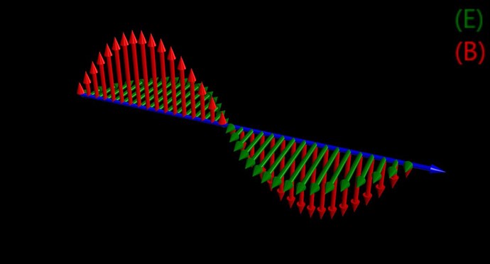
Electromagnetic Wave:


The Direction of the wave is in the direction of the Blue Arrow. The Wave Length is: λ = v / f - Where v is the speed of light in the medium one is using, and f is the Frequency.


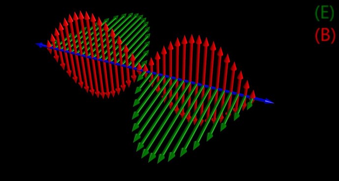
Standing Wave:


Two Wave Forms, each in opposite Directions, shown by the Blue Arrows. In this case, equal in Amplitude. However we see the Current Waveform, depicted in Green as ( E ), has double the amplitude. This waveform is a Standing Wave, two Current Waveforms traveling in opposite Directions Summing.

The Wavelength for a standing wave is: 0.5 λ

Floyd Sweet told us:

If the directions of the two signals are such that opposite H-fields cancel and E-fields add, an apparently steady E-field will be created. The energy density of the fields remain as calculated above, but the value of the E-field will double from E/2 to E.

A very interesting description by Wikipedia:

In one dimension, two waves with the same wavelength and amplitude, traveling in opposite directions will interfere and produce a standing wave or stationary wave. For example, a wave traveling to the right along a taut string held stationary at its right end will reflect back in the other direction along the string, and the two waves will superpose to produce a standing wave. To create a standing wave, the two oppositely directed waves must have the same amplitude and frequency. The phenomenon can be demonstrated mathematically by deriving the equation for the sum of two oppositely moving waves.


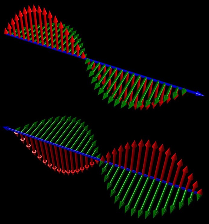
Please forgive my inaccurate depiction, but the following is supposed to show two waves equal, but travelling in opposite directions, the Arrows in the Current Waveform are in the same direction:


However, the Arrows in the Magnetic Waveform are in opposite Directions! 

Of course, the top and bottom waves in the above Image, when combined, create the wave below: A Standing Wave is the Current depicted in Green, which has double the Amplitude of each wave by itself.


So, the Current, because we know Standing Waves exist and we know how they are created, we know that this will Add, to create a Standing Wave.

Remembering, any wave can be made to be a Standing Wave, Magnetic, Water, Sound, light, hmm interesting...

We can build Noise Cancelling Headphones, but cant apply this Tech to Power?

   Chris

Jagau posted this 31 October 2018

Ok i  think  later in the document get my answerembarassed

quote:

waves are formed in different phases, where some are added, subtracted somewhere. Overall, therefore, these two effects cancel each other and the energy increment is not happening.  However, there is the so-called common-mode interference, in which occur only addition (in-phase) amplitudes of electromagnetic waves in the load. In this case the load generated by the additional energy in the form of heat or electricity


Jagau

Jagau posted this 31 October 2018

Hi Chris

Talking about this document ''Transgeneratsiya''

quote:

At the interference maxima of the intensity of the resultant wave is greater than the intensity of the incident waves and the interference minima less than their sum. Under the intensity here refers to the energy of the electromagnetic field.

Common-mode interference of electromagnetic waves is a mode used to filter the interference of a signal
I try to understand with 3 coils in series he talks about Common mode who normally this type of mode is like this:

he probably mean in a 3 phase sytem?

Jagau

  • Liked by
  • Chris
  • ISLab
Chris posted this 31 October 2018

My Friends,

Effectively, we could view a Circuit of the above Bulgarian device like so:


Where:

  • L1 and L2 are Non Inductive and are Current Amplification Windings. L1 and L2 Inductive component is almost Zero.
  • L3 is Inductive and is a Voltage Amplification Winding.
  • LA1 is the +1000 Watts Load


I really should not "Simplify" Circuits, as I do not like the effects seen when one changes the original circuit without having a proper understanding.  Conceptually, we get the objective on this Thread!

   Chris

Chris posted this 30 October 2018

My Friends,

We should consider a simple fact. Non-Inductive Coils, where the Turns are parallel and the wiring is equal and oppositely connected, thus giving very little to zero inductance, inherently is a NON Magnetically Coupled Device!


Meaning, a Transformer built on these principles would not work.

Non Inductive Coils, actually HIGHLY Inductive between each other, we have covered this before, can be Electrically Driven instead, or switched in at a specific Timing.


A common theme above, seen in many of the Russian Devices we have seen!

At Resonance, we get:

In the specific case of positive charges moving to the right and negative charges to the left, the effect of both actions is positive charge moving to the right.

Current to the right is: I = da+ / dt + da- / dt.


Negative electrons flowing to the left contribute to the current flowing to the right.


So, Current ( I ), in this schematic, will only ever be the same, because Resistance ( R ) has not changed, only internal Circuit Resistance remains. Ohms Law: I = V / R. However, the equation f = 1/sqrt(LC) is offset by a larger than usual factor, not related to Zeta.

If the Resistance ( R ) were to change periodically, at one point in the Cycle, say a Diode, or a switch were activated, switching in Resistance, then Current Compensation would be required to keep the Resonant Circuit.


So, Non-Inductive Coils, are inherently Electrical in Nature, not Magnetic, however, we do know that there is a Magnetic Component, Equal and Opposite, this Is a "Generative" Resonance, using the currently un-understood Law's of Electromagnetic Induction. Some 187 Years Old  wink

   Chris


P.S: Ironically, the Human Race has highly trained engineers that can not grasp these simple concepts and apply then to Power Engineering. Why? They have not the will, trained to ignore the most important aspect of all of todays technology: Powering it!

Chris posted this 30 October 2018

Hey Jagau,

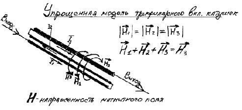
H3 is the resulting Field intensity and we cant change this. It is the Inductance that is resident in the Transformer arrangement:


The Current ( I ) and the Magnetic Field ( B or sometimes H ) are analogous to each other. One is the other. Indicated, all are equal to each other in the first bracketed Equation, then indication the H Vector of H1 and H2 are equal and opposite and thus cancel each other out leaving only H3.


Thus, the Magnetic Field H in this case, as there are three, we have an Action, a Reaction and also a Counter-Reaction, and thus a Asymmetrical, a Broken Symmetry, thus giving rise to open Systems, able to produce Energy Gains:


Current is Amplified and Voltage is also amplified in the same time frame. Don Smith also gave us the same information:

Please take a minute to watch and understand this short video


We see information that is standard Electromagnetic induction Laws, some 187 Years old. Still not fully understood today by Science.


If Q = XL/R and R is Zero, we have a large problem. We are not able to divide by Zero. Here we do see a Mathematical conundrum!


Resonance!


Where:

  • L1 and L2 are Non Inductive and are Current Amplification Windings. L1 and L2 Inductive component is almost Zero.
  • L3 is Inductive and is a Voltage Amplification Winding.

   Chris

Jagau posted this 30 October 2018

If I'm not mistaken a letter between 2 bars on each side, | H |
means the absolute value of the number without taking into account the sign + or -
And if this absolute number has a small arrow above, it means that it has a direction, a certain angle and a magnitude.
So | H1 | + | H2 | + | H3 | = | H3 | with each a small arrow above is an absolute number.

He could have written = | H4 | Why?


Jagau

  • Liked by
  • Chris
  • cd_sharp
Chris posted this 29 October 2018

My Friends,

We have seen this before, and it is ironic, Andrey Melnichenko told us some 10 years ago, the meaning of an image:


What's the meaning of this image? What's the purpose? It is simple when one takes a minute to really study:


Where:

  • L1 and L2 are Non Inductive and are Current Amplification Windings. L1 and L2 Inductive component is almost Zero.
  • L3 is Inductive and is a Voltage Amplification Winding.


We also saw the same meaning here:


Of course the switching component making it harder to understand. Tariel Kapanadze told us Andrey Melnichenko was right!


@ 37 : 07 in video: www.youtube.com / watch?v=3utQUdGDMmU

From a computer has pulled out the information about such person... Its surname is Melnichenko. The unique person, unique material with which I have had time to familiarise for the last years, who decided exactly this question. It speaks: hold a resonance and all will turn out.

As he said, it has not reached transformer Tesla. and has already begun work, to make this installation. he will make this device, to my mind, still it is not fast, but... he is very close.


We have covered this before. Now, I hope we have a much better understanding of what's being said here! We MUST Amplify both Voltage and also Current!

   Chris


Chris posted this 29 October 2018

Our Friends in the East continue to show us how to make these devices:


Links:


We have seen many machines run, many, perhaps if we look to our peers, we may just learn enough to be able to build our own.

Don Smith is perhaps one of the best resources we could have had. Others like Floyd Sweet, Ruslan, Akula and others have all been inspirations!

Very few have heeded the wisdom bestowed upon them from their Peers!

   Chris

Chris posted this 28 October 2018

My Friends,

The Mr Preva Experiment shows us how to Amplify Current, this is common knowledge to us now:


Floyd Sweet told us the same thing:


In the specific case of positive charges moving to the right and negative charges to the left, the effect of both actions is positive charge moving to the right.

Current to the right is: I = da+ / dt + da- / dt.


Negative electrons flowing to the left contribute to the current flowing to the right.


Now comes the next part, to amplify Current even further, Voltage must be Increased through Turns Step-Up.

Current ( I ) = Voltage ( V ) / Resistance ( R ), this is Ohms Law and it works all day long.

So, stepping the Voltage Up, and Non-Inductive Coil at Resonance, Magnetic Resonance, gives a Total Power Gain in Excess of the Power supplied to run the Device.

We have skeptics, and to be honest, really they mean nothing, but the people that can use their minds, use reason and logic, we have the evidence and the know how!

   Chris

We're Light Years Ahead!
Members Online:

No one online at the moment


What is a Scalar:

In physics, scalars are physical quantities that are unaffected by changes to a vector space basis. Scalars are often accompanied by units of measurement, as in "10 cm". Examples of scalar quantities are mass, distance, charge, volume, time, speed, and the magnitude of physical vectors in general.

You need to forget the Non-Sense that some spout with out knowing the actual Definition of the word Scalar! Some people talk absolute Bull Sh*t!

The pressure P in the formula P = pgh, pgh is a scalar that tells you the amount of this squashing force per unit area in a fluid.

A Scalar, having both direction and magnitude, can be anything! The Magnetic Field, a Charge moving, yet some Numb Nuts think it means Magic Science!

Message from God:

Hello my children. This is Yahweh, the one true Lord. You have found creation's secret. Now share it peacefully with the world.

Ref: Message from God written inside the Human Genome

God be in my head, and in my thinking.

God be in my eyes, and in my looking.

God be in my mouth, and in my speaking.

Oh, God be in my heart, and in my understanding.

Your Support:

More than anything else, your contributions to this forum are most important! We are trying to actively get all visitors involved, but we do only have a few main contributors, which are very much appreciated! If you would like to see more pages with more detailed experiments and answers, perhaps a contribution of another type maybe possible:

PayPal De-Platformed me!

They REFUSE to tell me why!

We now use Wise!

Donate
Use E-Mail: Chris at aboveunity.com

The content I am sharing is not only unique, but is changing the world as we know it! Please Support Us!

Thank You So Much!

Weeks High Earners:
The great Nikola Tesla:

Ere many generations pass, our machinery will be driven by a power obtainable at any point of the universe. This idea is not novel. Men have been led to it long ago by instinct or reason. It has been expressed in many ways, and in many places, in the history of old and new. We find it in the delightful myth of Antheus, who drives power from the earth; we find it among the subtle speculations of one of your splendid mathematicians, and in many hints and statements of thinkers of the present time. Throughout space there is energy. Is this energy static or kinetic? If static, our hopes are in vain; if kinetic - and this we know it is for certain - then it is a mere question of time when men will succeed in attaching their machinery to the very wheelwork of nature.

Experiments With Alternate Currents Of High Potential And High Frequency (February 1892).

Close