Induction in the Tank Circuit

  • 1.5K Views
  • Last Post 09 May 2020
Gravitation posted this 30 April 2020

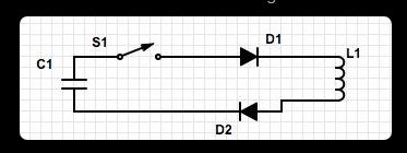
Let’s assume we have the following schematic :

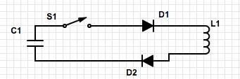
In this schematic we have a charged capacitor and a coil (diodes are here only to make a one way road for electrons)
Our goal in this circuit is to discharge the capacitor in the coil and show that there is more energy at the end of the operation.
Ok let’s go !

For our purposes we will use for example the following datas for the capacitor and the coil.
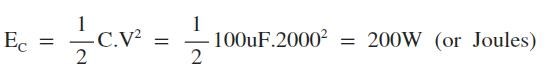
C1 = 100uF
L1 = 122mH
R1 = 10 Ohms
Capacitor C1 is charged to 2000V.
R1 is the resistance of the coil

Ok here we go :
So let’s compute the total energy stored in the capacitor :

Now i close the switch « S1 », electrons are flowing trough the coil L1.
Now we will compute the energy stored in the coil :

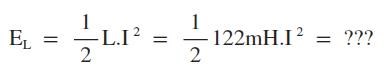
Ok but was is the value of « I » (current) ?

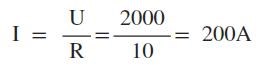
So let’s compute the total energy in the coil when i close the switch :
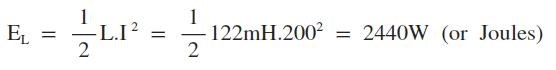
Finally :

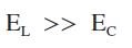
So, we can clearly see that there is more energy when the coil receive the voltage from our capacitor ! When you close the switch we make a strong short-circuit. All energy is then stored into the coil into the electro-magnetic form until it vanish when all electrons have passed and returned into the capacitor.

In this example i do not make an explanation on « how to retrieve this excess of energy » but just show that using theses basic equations we can "produce more energy".

Best results are with theses parameters :
Capacitor C1 must be the smaller as possible and with the highest voltage as possible.
Coil L1 must be the bigger as possible with the lowest resistance as possible


Order By: Standard | Newest | Votes
YoElMiCrO posted this 01 May 2020

Hello everyone.

@Gravitation.

This example shows that the charge conservation law appears to be violated,
This law was coined by Benjamin Franklin.

The initial charge of C1 is 26.4mC,if we transfer the charge directly to another capacitor of equal
value the load would be divided between two ideally, being this one of 13,2mC in each one of them.
If we now calculate the total voltage in them, it would be Q (initial) / 2 = Edc / 2 = 6Vdc.
However if we use the above circuit we will see that the sum of the charges
will exceed the initial load and as efficiency is (EndQ1+EndQ2)/StartQ1 AU is posible..

This says a lot, everyone start analyzing ...
Q = VcC = It.

Thank you all in advance.

YoElMiCrO.

Atti posted this 09 May 2020


I would like to thank Yoelmicro and Chris for their attention (and of course everyone’s work!) On the benefits of capacitor capacities.
Years ago, I performed JL Naudin’s experiment.http://jnaudin.free.fr/hep/index.htm

The result is impressive, but I was looking for something different then. I did not pay enough attention to the whole mechanism. Now that Yo has pointed out the point, I took some measurements. For information only. The similarities begin at the beginning of the video. The higher the C2 load, the more voltage there will be. If there is no diode, the power supply's internal capacitor voltage will also increase. Obviously it depends on other parameters as well, but an initial starting point will be a basic premise for me.
So thank you again!

I don’t remember the specific data anymore, but the power consumption has definitely dropped.


 ( Unfortunately, I will have a job for weeks now that I will not be able to do any experiments. I have to put everything in a box for a while. But I will follow the forum. I'll continue from here. )

Nagy Attila

Chris posted this 01 May 2020

My Friends,

@Gravitation, YoElMiCrO has given you the worlds biggest gift!

We see:

  • Method of "Generation", Charge Separation.
  • Charge Pumping, Opposite Magnetic Fields.
  • And more...


YoElMiCrO is right, this is very important!

However if we use the above circuit we will see that the sum of the charges will exceed the initial load and as efficiency is (EndQ1+EndQ2)/StartQ1 AU is posible..

This says a lot, everyone start analyzing ...
Q = VcC = It.


The Charge on a Capacitor is: Q = C٠V

Where C is the Capacitance in Farads and V is Volts. Q is in Coulombs if Memory serves. So this means, 2200uF = ‭0.0022‬ Farads. Voltage on the Capacitor is 12 Volts at the start. The switch S1, when closed has an RLC Time Constant across the Tank Circuit. For series RLC circuit Time Constant is 2L/R and for parallel RLC circuit Time Constant is 2RC. This means after 1 t, the Charge on C2 can be more than C1!

Note the Similarity to Akula's Circuit! Everyone! This is important! We all have to work on this together! We must Share this with the World! We must make change for our Children and their Children!

Best wishes,

   Chris Sykes

YoElMiCrO posted this 03 May 2020

Hello CD_Charp.

There is nothing to excuse, asking is wise.
First of all thank you, for that we are in this great forum, thanks to Chris.
To share knowledge among all, it will be easier to reach our only goal,
demonstrate once and for all that UA is real and not a crazy dream.

No, Vc2 will be the final voltage that our tester will measure as Chris says.
What we do is the following ...
We load C1 with a voltage of 12Vdc for example, the Sw1 will be open.
We downloaded C2, now the tester parallel to C1 will show 12Vdc and the parallel to C2
will show 0Vdc, we disconnect the power supply parallel to C1.
So far everything normal ...
We calculate the initial charge of C1 that will be Vdc*C1=12*2200*1*10-6=0.0264C=26.4mC.
In a lossless system, the loads are maintained, if we now transfer the load
to another capacitor of equal value, ideally they are divided between the two and it will be 1/2Qin = 13.2mC or
which is the same Vdc/2= 12/2 = 6Vdc in each capacitor.
If we transfer the initial charge of C1 through the previous circuit we will see that the law
Cargo conservation appears to be violated.
In the posted circuit, after transferring the C2 load, the voltages measured in
the experiment carried out by me were Vc1=6.5Vdc and Vc2=7.0Vdc.
If we calculate the loads of each one and add them we will see the following.
Q1=14.3mC and Q2=15.4mC, so the final charge is 29.7mC.
If we now calculate whether the law is followed ...
Qt (End) / Q (start) = 29.7/26.4=1,125 ...
If we recharge C1 and reload C2, the efficiency becomes 2.5.
Something incredible, but real, this shows that AU is more than possible !!!!

I hope it helps you.

YoElMiCrO.

raivope posted this 01 May 2020

Hi Yo!

I guess there is one more explanation of AU in your circuit. During magnetization of 7T, 11T does opposite work and reduces inductance. During CEMF you collect energy from 7T where inductance is bigger. Inductance (permeability as a parameter) is dynamic and if you have toroid (probably with a cap) having coils in each end. Material should be permalloy or something with low saturation level.

Raivo

Chris posted this 02 May 2020

My Friends,

I should have finished the Equation off!

The Charge on a Capacitor is: Q = C٠V

Where:

  • C is the Capacitance in Farads.
  • V is the Voltage in Volts.
  • Q is in Coulombs. 1 Joule (J) = 1 Volt X 1 Coulomb.


So this means, 2200uF = ‭0.0022‬ Farads. Voltage on the Capacitor is 12 Volts at the start.

As YoElMiCrO said: 

StartQ1 = 0.0022‬ Farads x 12 Volts = ‭0.0264‬ Coulombs.


using the same process, if C1 and C2 ( EndQ1 + EndQ2 ), after 1 Cycle has: ‭0.0265‬ Coulombs, then we have an Above Unity Machine. More Energy Output than was Input!

NOTE: This is possible because we have an Open System, a System that has an Extra, Asymmetrical Energy Input to the System!

Best wishes,

   Chris Sykes

Jagau posted this 02 May 2020

 Hi all

if we talk about this circuit

 When current is allowed to pass through an inductor, it is found that the voltage across the inductor is directly proportional to the time rate of change of the current.


So if you look at equation above, for an inductor to have voltage across its terminals, its current must vary with time.

 Hence, v = 0 if we have a constant current through the inductor.

 there is no accumulation of stored energy in an inductor if its current is not varying with time, 

it just a fantastic short circuit to DC current once switch is close. or beautifull spark on the switch.

1 joule is not equal to 1 watt

1 joule equal 1 watt X time  and 1 watt = 1 joule / time it could be in second

Hope this help

jagau

raivope posted this 30 April 2020

Current cannot rise to 200A, because energy conservation law , I mean because coil will create opposing voltage when its current/magnetic field rises in time. Opposing voltage reduces the maximum possible current. Probably, current can reach not more than 57A.

Zanzal posted this 30 April 2020

A simulator like Falstad's circuit simulator can help you to test these ideas. You may want to consider adding in some small resistances like 0.01 ohm and such to ensure your not dealing with unrealistic components. 

I tried really hard to find exploits related to the exchange of Joules and Coulombs using inductors and capacitors. While I was ultimately unsuccessful myself, I learned so much trying that I recommend others try if only to learn about how these components exchange energy.


Chris posted this 09 May 2020

Hey Atti,

Excellent this is great to see! Good work! Thank You for Sharing!

When you say:

I did not pay enough attention to the whole mechanism.


This is why we are here, to share and to guide others that have a learning process in front of them. This is all about Understanding! It really is!

Best wishes, thank You again for sharing! Stay safe and well!

   Chris

Chris posted this 01 May 2020

Hey Gravitation,

I decided to delete my post, the post you reference, to see how this thread pans out, to see if you can turn it around, to give you some time to get the thread on target before I had to clamp down.

I am glad you replied, I am grateful you have explained! Thank You!

Please understand, I have to be wary of any new / relatively new accounts, to protect Members here.

All Members are welcome! But please understand, I have a job to do, and a Team I need to keep safe! We have a credibility to keep and up hold. We can not be seen as Cooks with unreliable Information and Data!

How about we change the Name of the Thread? As in something less controversial for those more experienced in the field.

Perhaps something like "Induction in the Tank Circuit"?

I try hard to uphold a forum with Honor and High Standards, so please understand, we have a lot of responsibility on our shoulders.

Best wishes,

   Chris Sykes

Chris posted this 01 May 2020

Hey Gravitation,

If you want to progress, read and study the threads:

 Romanian ZPM
 Wistiti's Bucking Joule Thief
 Yo's Ferro-Magnetic Resonance
 Jagau's Non-linear Resonance
 Non-Inductive Coil Experiment


It is up to you. If you are not interested in learning what we have to share, then no problem. Its your choice!

We will not punish anyone for a mistake, thus accepting your apology. So please understand, we all make mistakes, its ok, so no more about it ok?

Time is running out, we don't have long to go. What will happen, I don't know, but I have worked very hard to try to be as prepared as I can!

You are welcome to ask questions! We all will help you as much as we can! All of us! Many of us are at different stages of progression, but all here will help where they can.

You are Safe here! So relax, learn as much as you can, share as much as you can, share your experiments as you progress, put your PayPal Donate buttons for some extra funds, do all you can. Do what you wish.

Best wishes,

   Chris

mich posted this 04 May 2020

thank you YoElMiCrO, very interesting.

I would submit to all also this link seems in support of what you said: https://edoc.pub/000-free-energy-plans-2-pdf-free.html

good day.

Gravitation posted this 30 April 2020

You think ? Even in DC current ? Because here we do not have a changing direction of current. Lenz Law cannot be applyed here.

Gravitation posted this 01 May 2020

Hey Chris,

Yes i understand all you said and this is normal for a great forum like you have. You protect the wonderfull job that you are doing. So sorry to put some "rubish" on your place.

Yes here we go for the "Induction in the Tank Circuit" title. I can also propose you "Basic error : induction in the Tank Circuit". Or remove it simply if it not usefull.

And also, sorry to disturb your work because i do not have seen that you are working on the ZPM device which shows interesting results actually.

We know that time is running out. Time is always precious but now it is worst


Atti posted this 01 May 2020

Hey Gravitation.

I would like to ask you if we can see any compilation from you about the theory outlined? Thank you for your answer.

Atti

Gravitation posted this 01 May 2020

Dear Chris,

I will post your reply here because i cannot find your answer in the comments :

This is an off topic post for our forum.

I will give you One Post to satisfy me why you should keep this post here.

There is no form of "Generation"!
There is no method of operation!
This simple circuit has been tested many thousands of time through history, including my myself and no one has ever claimed any unusual results before!
I think you are here to waste time of Members - Trolling!
This is a Distraction to our current path!

What is this! Who are you? Why are you here trying to distract us?

One explanation, one chance!

Best wishes,

Chris

To answer you, i'm not a troll and not wasting time of Members. I was just showing a thinking that i note. I'm aware that this simple circuit is one of the most famous ever tested through history in the world. But to be honnest i don't think that no one has ever claimed any unusual result. For example Don Smith claimed over-unity with his circuit. Basically, his circuit is based on resonance.

For sure, following the simple circuit that i posted before, will give you nothing. As you know very well, we must complete this scheme to have a functionnal unit. Don Smith's circuit is one example of a complete circuit.

Now for educationnal purposes and to fix my post, for quoting Raivope's reply:

Raivope says :

Current cannot rise to 200A, because energy conservation law , I mean because coil will create opposing voltage when its current/magnetic field rises in time. Opposing voltage reduces the maximum possible current. Probably, current can reach not more than 57A.

Sorry Raivope ! You right ! I misunderstood your reply. It's not the Lenz Law that there is involved here. But as you said the "coil will create opposing voltage when its current/magnetic field rises in time".

Now for Chris : you can remove the topic or move it to another subject classed like "things to not reproduce" or "basic errors" etc. I don't think i will be the last to make this error.

For all, thanks your return and reply !


  • Liked by
  • Chris
  • Augenblick
We're Light Years Ahead!
Members Online:
What is a Scalar:

In physics, scalars are physical quantities that are unaffected by changes to a vector space basis. Scalars are often accompanied by units of measurement, as in "10 cm". Examples of scalar quantities are mass, distance, charge, volume, time, speed, and the magnitude of physical vectors in general.

You need to forget the Non-Sense that some spout with out knowing the actual Definition of the word Scalar! Some people talk absolute Bull Sh*t!

The pressure P in the formula P = pgh, pgh is a scalar that tells you the amount of this squashing force per unit area in a fluid.

A Scalar, having both direction and magnitude, can be anything! The Magnetic Field, a Charge moving, yet some Numb Nuts think it means Magic Science!

Message from God:

Hello my children. This is Yahweh, the one true Lord. You have found creation's secret. Now share it peacefully with the world.

Ref: Message from God written inside the Human Genome

God be in my head, and in my thinking.

God be in my eyes, and in my looking.

God be in my mouth, and in my speaking.

Oh, God be in my heart, and in my understanding.

Your Support:

More than anything else, your contributions to this forum are most important! We are trying to actively get all visitors involved, but we do only have a few main contributors, which are very much appreciated! If you would like to see more pages with more detailed experiments and answers, perhaps a contribution of another type maybe possible:

PayPal De-Platformed me!

They REFUSE to tell me why!

We now use Wise!

Donate
Use E-Mail: Chris at aboveunity.com

The content I am sharing is not only unique, but is changing the world as we know it! Please Support Us!

Thank You So Much!

Weeks High Earners:
The great Nikola Tesla:

Ere many generations pass, our machinery will be driven by a power obtainable at any point of the universe. This idea is not novel. Men have been led to it long ago by instinct or reason. It has been expressed in many ways, and in many places, in the history of old and new. We find it in the delightful myth of Antheus, who drives power from the earth; we find it among the subtle speculations of one of your splendid mathematicians, and in many hints and statements of thinkers of the present time. Throughout space there is energy. Is this energy static or kinetic? If static, our hopes are in vain; if kinetic - and this we know it is for certain - then it is a mere question of time when men will succeed in attaching their machinery to the very wheelwork of nature.

Experiments With Alternate Currents Of High Potential And High Frequency (February 1892).

Close